Man, you guys sure write alot.
Brian, I was just noting the lower part of my response.
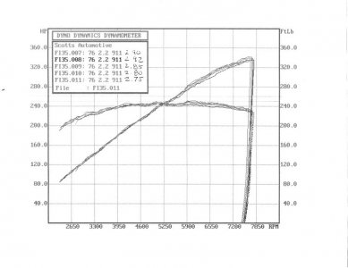
Essentially, the problem that led me to believe that the ESM voltages modified the ECU fuel trim/timing was the detonation I was getting. Between approximately 2.75 and 2.90, I was getting detonation. It gradually decreased as it approached 2.90. Between approximately 2.90 and 2.98, no detonation. Between 2.98 and 3.10 detonation gradually increased. I finally through a code at 3.17. From what I was previously told, once the ESM sees 2.92 volts it goes into max load conditions. Therefore, in theory a higher voltage should do nothing, until of course the ESM thinks there is too much boost in the NA engine and throughs a code. However, the power in the higher ESM voltages 2.98-3.10 went way south. The odd part of this whole series of tests was that the a/f ratios were nearly the same for all test conditions 2.75-3.10, which would make me think that the timing may the the predominate variable.
Further, during some of the dyno tests, and road tests, we measured the ESM's output voltage, and they were pretty consistent at -0.2 volts when compared to the ESM's tab voltage.
Given these data points for a specific engine/blower, there must be a point which would yield max hp/tq, and still not detonate.
What do you guys think.

") . If there was no other annotation, I would have guessed that the variation was only a result of measurement variability.
. If there was no other annotation, I would have guessed that the variation was only a result of measurement variability.