• Protip: Profile posts are public! Use Conversations to message other members privately. Everyone can see the content of a profile post.

91-92 Keyless Solved

shawn110975

Suspended
Joined
15 July 2009
Messages
7,726
Location
Arizona
Ok guys I solved the 1991-1992 Keyless entry Problem.

First I need to thank the other PRIME members that helped with this in one way or another.

White92 for supplying the Service Manuals for most of the NSX years.

ffffanman for posting the original install Instructions

UnhuZ for creating the wiring Diagram on another thread.

Sudesh for all of his pics and experience regarding this thread
http://www.nsxprime.com/forums/showthread.php?t=109139&highlight=keyless

Nikey22 for giving me great ideas for this.

I had to go to a junk yard and cut the 22P 8P and 16P female and Male connectors from various hondas. and its HOT as Shit here in Florida dripping sweat. Uggggh

OK here we go sorry for the Run-on sentences and bad Grammar Up front.
deal with it. LOL

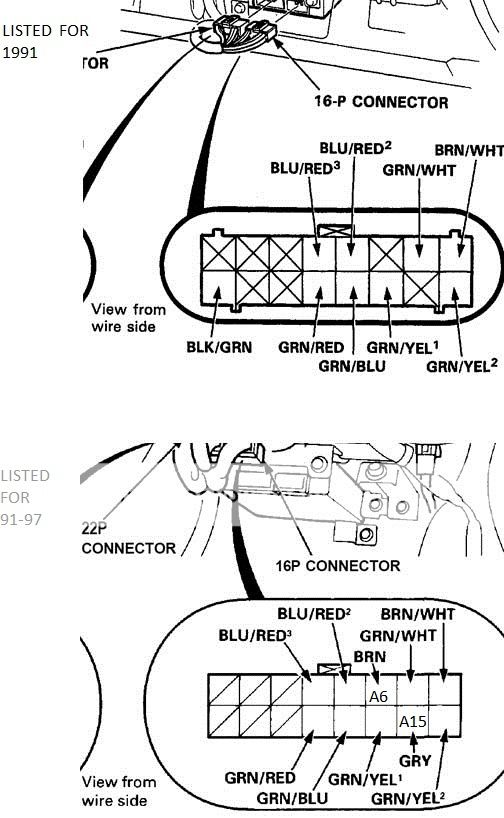
After you take the lower bolster out and glove box Door, you then need to remove the actual glovebox. unplug the light and Valet trunk Lock and the AC tube, you will see the Security Control Unit (SCU) at the bottom of a tower of other small boxes, abs etc. the SCU is the one on the bottom.

the ( SCU ) has 2 plugs going into it one grey 22P connector and a grey 16P connector

on the Original install instructions provided by ffffanman
we see on page 2 that there is 2 wires, red and yellow, that need to be inserted in to the 16P connector on the Security Control Unit ( SCU )

I could not find anything in the NSX Manual for my 1992 NSX regarding these two wires.

on the 1993-1995 Acura Legend Manual these wires are
set-output and reset-output.
but they did nothing that I could find.

looking at the grey 22P connector on the (SCU)
the big one on the left.
there are 2 wires you will need to tap into which
is Lock and Unlock
or Lock request and Unlock Request,
pin 9 on the 22P connector is Arm/Lock GREY/WHT Stripe
and pin 1 on the 16P connector is Disarm/Unlock GRN/YEL Stripe
they call it something different every year, its funny.

next there is this 8P MALE connector that is already in your NSX which has Blue Tape holding it up near the top of all these wires. leading to the (SCU)

ORG is Batt +
BLUE/GRN Stripe is Ignition Key Input.
BLK is Ground -
YEL/GRN Stripe is Hood Switch
GRN/WHT is L Key Cylinder Switch
WHT/YEL not in the Service Manual
GRN/BLUE Stripe is Door Switches

now the wiring Diagram from the 2004 Keyless Entry Kit Provided by
UnhuZ show the following

this is a 12P FEMALE connector
Orange is Battery +
BLUE/GRN Stripe is Ignition Key Input
GRN/WHT Stripe is Lock Request
WHT/YEL Stripe is Unlock Request
BLUE is Engine Lid Input
BLK is Ground
GRN is Door Open Input
RED is Hood, Trunk, Engine Hatch Open Input
BRN is ARM
GREY is Disarm

its easy once you know where the wires go.

after I wired the 2004 Harness to fit into the NSX 8P Male connector with a Female 8P and the 12P MALE into the 12P FEMALE

now I though that the RED and YEL wires from the Original Install instructons at the 16P MALE connected to the ( SCU ) was the lock unlock request or Lock/Unlock they are not. I dont know what they do
I went thru all the NSX years with the Manuals and nothing that I could find.

the JOY I felt when I pressed the Lock button on my remote and the doors locked and the Security system was blinking Active at the driverside door.

Now I was tring to create a Plug and Play Kit but as you need to tap into 2 wires GREY/WHT stripe and GRN/YEL Stripe its not a truly a plug and play Kit. but damn close.

the bottom line is

you need to buy the 2004 NSX keyless Entry Kit from the Dealer for around 450 and I can supply my new Harness for a fee.

any one can make this harness but Lots of people dont want to mess with it. so thats why I am offering it as a already made kit.

now my 1992 NSX has the 2004 Keyless Entry system installed.

heres what happens

when I hit the button on my Remote the car locks and unlocks
and arms and disarms the Security System.
opening any door or hatch will trigger the alarm. like normal.
the keyless entry system AUTO Locks after 15 seconds.
but if the Key is in the ignition it will not lock the doors.
if the car is locked from the inside and you walk away
the Keyless entry system will lock the car again.

Panic button on the remote does not activate the alarm (dont ask lol )
This does not Blink the parking lights for Confirmation

if you would like to get this Harness PM me

my kit will include the harness needed to connect to your 2004 NSX system zip-ties a few splice buttons so you can tap the 2 wires and extra if you mess up the splice button.

thanks to all that helped and If I missed anyone thanks

Shawn


I LOVE PRIME..........dont you?
 
Last edited:
Also I will work on it some more so we can get the panic button to work
and the Blink lights for confirmation of system arming

Shawn
 
I'm surprised that members aren't making a bigger deal out of this. After all, it does come as close to solving our discontinued-'91-brain problem as anything I've seen yet.
Sure, the remote brain from a more recent model NSX costs as much as a new set of tires. But here's an opportunity to stay OEM and also trigger the car's built-in alarm system when locking.:smile:
 
I have the original '91 keyless on my car and the panic button only works intermittantly. Not sure what the process or button sequence is to get the panic to work.
 
Sure, the remote brain from a more recent model NSX costs as much as a new set of tires. But here's an opportunity to stay OEM and also trigger the car's built-in alarm system when locking.:smile:

Not a set of OEM tires. :wink:

Hat's off to Shawn, this was a nice piece of work.
 
Congrats to Shawn, this has been an issue since 2006, and its finally solved!

P.S. there is no reason why a more modern remote (oval shaped gray FOB) from the newer cars won't work with this set up.. It should. More detective work is required but I'm sure we'll get this to work, as there are a ton of these types of FOBs on ebay for real cheap.
 
Rock on!

I've got a little KB when I worked on trying to get the panic button to open the trunk.

1. The driver and passenger door switches are separate. The doors should not lock if the driver door has been opened.

2. The panic appears to fire if the UnLock and Lock request come in at the same time.

3. The trunk unlock is buried in the main interior harness and only easily available at the door mounted switch.

4. You can buy connector shells and the m-f connectors, but you have to buy them by the thousand. They will give a few complete sets away as a sample. I have the catalogs, but all my contacts are no good: the operation moved from the bitter North to the South.

Sumitomo Wiring Systems.
http://www.sewsus.com/welcome.html
sws.co.jp
 
Congrats to Shawn, this has been an issue since 2006, and its finally solved!

P.S. there is no reason why a more modern remote (oval shaped gray FOB) from the newer cars won't work with this set up.. It should. More detective work is required but I'm sure we'll get this to work, as there are a ton of these types of FOBs on ebay for real cheap.

Hope so. I'd like to have the more modern fob.
 
Another thing, Shawn110975 said this in another thread:

Got my 2004 NSX keyless entry today.
and I thought the remotes were the newer style,
oval shape but nope they are the same as the old square ones

also the Brain for the Keyless entry has the Acura legend Part number on it.

so we know for a FACT they are compatible now.

P/N 08E61-SP1-2000-02

the Keyless Kit part number is 08E60-SLO-201F

will start this project today.

wish me luck lol


So I wonder if it would be any cheaper buying a Legend brain instead of getting soaked just because we asked for an NSX one. And if we did order the Legend brain, would the other bits that came with it be a mismatch for the NSX?
I probably should just quit thinking about it and bite the bullet.:redface:
 
Last edited:
the legend brain can be found at any junk yard.

now the Harness is totally different,
but if you cut about 7-8 inches worth of length from the Legend Harness going to the Legend brain you would be halfway there when making your own harness. now the next step is getting the Female Connector from under the Legend Driverside dash. there is shit load of different Plugs but if you took a pic of the Female plug you needed you would be almost there.

next step is getting a remote for the Legend brain you just pulled.
they dont sell them. only place I have seen that sells them is e-bay.
and

http://www.originalkeyless.com/1992...-92-NSX-Coupe-92-NSX-Keyless-Entry-Remote.htm

last step would be connecting the correct wires to the female connector and the male connector that goes into the Legend brain.

now I have read that there is this learn switch inside the Brains. so I took one apart and yes I can confirm for a fact that there is a learn switch inside these brains, NSX and Legend.

now programming this remote I have not tried it out as my kit was already programmed.

if you get these parts I can give you step by step instructions on how to connect the wires.

its not really hard if you can install a car radio you can install this.
 
I have enough parts to make tons of Harness's for 1991-1992 keyless entry pm me if you want one price is $100.00

ALSO if you have a 1993-2005 brain with no harness i can make them to. I just made a few and am happy with the results.

PM me if any one needs one just tell me what year so I can send you the proper harness.

now you can get slightly used remotes from this site

http://www.originalkeyless.com/

I hope I have helped people with this Old Issue
 
Last edited:
Resurrecting this thread. Shawn, your 2004 schematic describes a brown (ARM) and gray (DISARM) wire coming off of the 2004 keyless harness. Are these wires the same as the red and yellow on the 91-92 keyless kit? I am trying to get my aftermarket alarm to arm the OEM.

In the 91 instructions, it says to plug the yellow wire into pin 2 and red wire into pin 11 on the OEM security 16-pin connector. I am fairly sure these are arm and disarm connections. Is it the same for the 2004 brown and gray wires? If I can connect my lock and unlock wires from my alarm to these pins, I am hoping I can arm and disarm the OEM alarm without cutting or splicing the factory harness.

Do we know which one is which, i.e., is the yellow ARM and red DISARM? Anyone know?
 
Awesome work Shawn,
Was thinking of changing mine to the 04-05 also. got any more kits?

Thanks
Mike


Honcho, here man this should help you out.


Fyi... the count for the plug as pictured is
A1 A2 A3 A4 A5 A6 A7 A8
A9 A10 A11 A12 A13 A14 A15 A16


So actually it's A6 (brown) or red and A15 (gray) or yellow


f7e0cc6b.jpg
 
Last edited:
Thanks Comtec! A couple of questions- are you sure it is A6 and A15? The diagrams in the servcie manual say "view from wire side." And, the 91 keyless manual shows the pin locations from the wire side. That is why I thought it was A2 and A11, since if you were inserting from the wire side and not the plug side, that is where they would line up. Am I wrong?

Second, do you know what kind of signal is sent by the keyless unit through the Brown (Red) and Gray (Yellow) wires? My alarm sends a (-) 200 mA signal on the lock and unlock wires- basically it just sends a ground. Is it simply a matter of tapping into these lock and unlock wires and plugging the pins into the SCU harness? Or, do I need to change to a (+) signal (I guess through a relay) to get the SCU to trip?

Also, does anyone know what size and type the red and yellow terminals are to fit into the OEM harness? I'm guessing Shawn has a good idea from his kits. ;)

Edit- this thread has given me hope!
 
Last edited:
Yes that is the numbering. In the 2002+ SCU drawing the number are included. I think one of the drawings is upside down if you look at the locking tabs. Looking from the wire side just means looking at a plug when it's connected, that direction. The orientation of the drawing above looks more correct then the one from the kit especially since they don't include numbering.

Mike
 
Why not a S2000 keyless entry.

I haven't done this but I've worked on a few alarms system on S2000 and looking at the keyless entry, the wiring is simular to 2004 and 2005 NSX keyless entry. The good thing about this is the S2000 keyless entry has the pop truck button on the remote. I was going to do this on my 04 NSX but I figured another way to pop my truck using the factory remote and I didn't want to buy a S2000 brain and remotes.

Like I said I never done this but I know it will work with very little modification on 2004 and 2005 NSX's harness. Good luck!
 
Hey guys, i got a question i just bought a 91 Nsx and it only came with 1 key and no remote, do all of them come with a keyless entry ? i would like to get the replacement remote as i try to lock it with the key it sometimes locks and then unlocks it self as im pulling the key off the lock. Anyone had this issues before?
 
sorry guys I didnt know anyone bumped this thread.

the last post WldNsx if you feel up under your passenger knee bolster if you feel a square box then your NSX had the keyless Option installed if its not there
then you probably dont have it.

finding a remote for it will be 100% impossible you can buy buy buy remotes from different sites but its not programed for your brain.
and NO the learn switch inside the brain does nothing.
and that guy that claimed to have programmed his remotes
says he doesnt really know how he did it. LOL

Honcho why didnt you just PM me bro.

pin 9 on the 22P connector is Arm/Lock GREY/WHT Stripe
and pin 1 on the 16P connector is Disarm/Unlock GRN/YEL Stripe


in the original instructions it shows you need to insert the new pins
into the original pigtail, in the electrical manual they had no use that I could find. I may have over looked something but hell I made the harness work for about 20 people. and they are happy. LOL

so honcho if your aftermarket alarm has a single arm wire and a single disarm wire
then yes if you tap into these 2 wires it will disarm/arm your oem alarm including the aftermarket.
but I must say that both alarms will go off in a triggered event.

most alarm shops tap these 2 wires to get the desired effect.

now after you hook up these 2 wires and you press lock and the car unlocks then you need to swap the wires with each other.
so if you press unlock on the remote and the car locks you have thoes wires backwards.

hope this helps guys.

if I can help let me know.

I have OEM paperback service/ electrical manual for all years.
 
Last edited:
Anybody have the 14P green connector pinout for the keyless module side?

I removed the keyless from my LHD 1991 when I sold it. I now have a RHD NSX and attempting a conversion of keyless into that. The problem is that the RHD has a 14P grey connector (seems USDM has 12P from 1993+, and an 8P +2 for 1991-2), so I am unsure on the conversion.

The vehicle side color codes are different from year to year and the keyless harness is different too.
 
Building your own DIY Keyless Notes. It should work for any NSX from 1991-2001.

The terminal relative positions are viewed from the wire side on female terminal connectors with the barb retainer on top, the terminals are numbered right to left. The male terminal connector is viewed with the barb on top and the terminals toward you. The gender of the plastic connector shell is opposite of the terminals inside: important to note!

The connectors are
Grey is Sumitomo HD 090
Green is JAE IL-AG5
Dark Grey is AMP MultiLock (used for the loose red and yellow wires that plug into the Security Control Unit [SCU]), either the 040 or 070 series. They can be salvaged from Integra ECU connectors, the 91-95 Legend SCU.
Brown is Sumitomo HD 250 (not used on keyless, just an FYI)
OEM Reference here: http://prd.sws.co.jp/components/en/
Purchase here: http://www.cycleterminal.com/motorcycle-connectors.html

The door lock and hood/hatch isolation diodes are unnecessary as they were over-engineered by Honda and the keyless harness was later simplified without them. Repeat: The OEM keyless harness does NOT require diodes. (Aftermarket, does require them to separate the un/lock from the dis/arm as the request wire is doing double duty. Aftermarket Keyless Integration see below).


The keyless harness green 14P connector (C598) for the keyless unit is as follows
(pin number, wire color, purpose, connector path)
1. YEL/GRN, hood switch, engine hatch switch. All closed = 12V, Any open = To ground, 0V
2. GRN/RED, UnLock (C460), Momentary to Ground, Unlocks doors
3. GRN/WHT, Lock (C460), Momentary to Ground Locks doors
4. BLU/GRN, Ignition key switch input (C452>C445), No key = 12V, Key in ignition switch = 0V
5. [not used]
6. ORG/GRN, 12V power, (C452>C249), battery power
7. [not used]
8. YEL, Disarm, (C452>C462), Loose wire, AMP terminal, to SCU 16P-15. Momentary 12V to Ground to Disarm.
9. RED, Arm, (C452>C462), Loose wire, AMP terminal, to SCU 16P-6. Momentary 12V to Ground to Arm.
10. [not used]
11. [not used]
12. GRN/BLU, Driver door switch (C452>C409>C615), Closed = 12V, Open = Ground
13. [not used]
14. BLK, Ground (C452>C417>G401)

The keyless harness grey 8P connector
1. YLW/GRN, Hood or engine open
2. GRN/RED, UnLock request
3. GRN/WHT, Lock request
4. [not used]
5. BLK, Ground
6. BLU/GRN, Ignition switch
7. GRN/BLU, Driver door open
8. ORG/GRN, 12V battery power, 3A fuse

[loose, no shell], RED, 12V momentary to 0V to arm, AMP Multilock female connector
[loose, no shell], YLW, 12V momentary to 0V to disarm, AMP Multilock female connector


This is your starting point, your Keyless Unit:
Keyless Connector Green 14P, wire side, female terminal connectors
━━━━━━━━━━━━━━━━━━━━━━━━━━━━━━━━━━━━━━━━━━━━━━━━━━━━━━
│1 YLW/GRN│2 GRN/RED│3 GRN/WHT│ ┕─────┛ │4 BLU │5 [empty]│6 ORG/GRN│
━━━━━━━━━━━━━━━━━━━━━━━━━━━━━━━━━━━━━━━━━━━━━━━━━━━━━━
│7 [empty]│8 YEL │9 RED │10 [empty]│11 [empty]│12 BLU/GRN│13 [EMPTY]│14 BLK │
━━━━━━━━━━━━━━━━━━━━━━━━━━━━━━━━━━━━━━━━━━━━━━━━━━━━━━

If you have a 91/92 then get this connector:
8P Bodyside connector, Grey 8P, terminal side, male terminal connectors
━━━━━━━━━━━━━━━━━━━━━━━━━━━━━
│1 YEL/GRN │ ┕─────┛ │2 GRN/RED│3 GRN/WHT│
━━━━━━━━━━━━━━━━━━━━━━━━━━━━━
│4 [empty] │5 BLK │6 BLU/GRN │7 GRN/BLU│8 ORG/GRN│
━━━━━━━━━━━━━━━━━━━━━━━━━━━━━

2x AMP
RED = Loose female terminal, no shell
YLW = Loose female terminal, no shell

12P Body Side connection. USDM 1993-2005
Female connector shell with male pins, terminal side number positions.
1. ORG, 12V
2. GRN/RED, Door Open Input, “E” passenger side
3. GRY, Disarm Request
4. WHT/YEL, Unlock Request
5. BLK, Ground
6. WHT, Trunk Latch Switch, goes to Hood or Trunk or Engine Open
7. GRN/BLU, Door Open Input, “D” driver-side
8. BLU, Engine Compartment Lid switch,
9. YEL/GRN, Hood Switch
10. BRN, Arm Request
11. GRN/WHT, Lock Request
12. BLU/GRN, Ignition Key Switch Input, “C”


If you have a 14P body side connector then use this. Also applies to JDM NA1-120 series
Grey 14P, terminal side, male terminals
━━━━━━━━━━━━━━━━━━━━━━━━━━━━━━━━━━━━━━━━━━━━━━━━━━━━━━
│1 [not used]│2 ORG (12V)│3 [unknown]│ ┕─────┛ │4 YLW │5 GRN/RED│6 BLK │
━━━━━━━━━━━━━━━━━━━━━━━━━━━━━━━━━━━━━━━━━━━━━━━━━━━━━━
│7 [unknown] │8 [unknown]│9 BLU/GRN│10 YLW/GRN│11 [unknown]│12 RED │13 GRN/WHT│14 BLU │
━━━━━━━━━━━━━━━━━━━━━━━━━━━━━━━━━━━━━━━━━━━━━━━━━━━━━━
1. Empty/Not Used
2. ORG, 12V
3. Unknown, Grounded
4. YLW, Disarm Request
5. GRN/RED, UnLock
6. BLK, Ground
7. Unknown, Open
8. Unknown, Grounded
9. BLU/GRN, Driver door
10. YLW/GRN, Hood, Engine Compartment, Trunk
11. Unknown, Grounded
12. RED, Arm Request
13. GRN/WHT, Lock
14. BLU, Ignition key

The JDM NA1-100's without an SCU also have a 12P connector with the best guess pinout
(terminal side)
1P, RED/YLW = unknown
2P, BLU = engine compartment open
3P, BLU/GRN = Key in the ignition output 12V
4P, WHT/YEL = Unlock
5P, GRN/WHT = Lock
6P, LTGRN/WHT = unknown
7P, YLW/GRN = hood open
8P, WHT = trunk open
9P, GRN/RED Passenger door open
10P, BLK = Ground
11P, GRN/BLU = Driver door Open
12P, ORG = 12V

The NA1-100's, model years 1990-1992 approximately, required a kludge add-on harness 08E55-SL0-0003 that connects to the 12P vehicle side connector. It also has interfaces with the ignition switch and has a starter interrupt relay. The harness is routed from the ignition switch, behind the radio, and to the passenger side under the dash. There is a 3A fuse inline that is roughly behind the radio but can be accessed from the passenger side dash.

The security LED is located in the center console and shines through a blank switch cover with a ~3mm hole in it. This system uses a bulky IR receiver on the driver door, a switch bank under the steering wheel, and a 30P integrated Security/Keyless unit. The system was unreliable and likely none work today.

The harness, led, switch bank is often behind and can be integrated with a modern keyless. The female 30P connector is only available in PCB mount, so recommend a repin to smaller connector such as a 22P version that has matching wired connectors.

Pinout, 30P green, connector side
Pin 1, not used
Pin 2, YLW alarm panel (under driver dash)
Pin 3, RED alarm panel
Pin 4, BLU, alarm panel
Pin 5, not used
Pin 6, not used
Pin 7, GRN/WHT = LOCK (? original unit used 7 to request lock, and 22 to monitor)
Pin 8, ORG = 12V
Pin 9, not used
Pin 10, not used
Pin 11, BLK = Ground
Pin 12, not used
Pin 13, LTGRN/WHT, unknown
Pin 14, not used
Pin 15, GRN/BLU Driver door Open
Pin 16, GRN/RED Passenger door open
Pin 17, not used
Pin 18, YLW/GRN, hood open
Pin 19, WHT trunk open
Pin 20, BLU, engine compartment open
Pin 21, WHT/YEL Unlock
Pin 22, not used
Pin 23, GRN/WHT = Lock
Pin 24, not used
Pin 25, BLU/GRN, Key in the ignition outputs 12V
Pin 26, not used
Pin 27, not used
Pin 28, ORG/YLW, unknown
Pin 29, GRN, starter relay cut needs 12V
Pin 30, YLW/BLK, LED at console next to e-brake handle Unknown voltage, could be 3.3V, 5V or 12V. Start low and go high to test.


Aftermarket Keyless Integration? Yes, an aftermarket keyless entry (even those costing under USD$20) system can easily be integrated into the NSX's body side connector. The dis/arm and un/lock (isolated with a cheap diode) just have to momentarily go to ground/0v. This momentary connection to ground can be duplicated with the aftermarket keyless un/lock request going to ground to the body side connector un/lock wires, and a diode separating the dis/arm request also to the body side connector dis/arm wires.

It is elegant, simple, reliable as well as inexpensive.

One could include a trunk release and flashing lights with a bit of extra work, but duplicating the functionality of the factory keyless can be had for an hour of time and $40. This is in price comparison with a period-correct vintage system costing +USD$550. A more modern Honda receiver, those with a connector >5 wires, can also be integrated into the NSX, but even those are pricey at +US$200.

I_M_Legend has kindly written up a DIY for this:
http://www.nsxprime.com/forum/showt...actory-Alarm-activation?p=2013354#post2013354
 
Last edited:
update (previous entry is locked)


Numbering is with connector shell barb on TOP, upper right is #1 pin and increments from right to left. The connector shell barb takes up two connector positions and not counted.
The female connector shell (holds male pins inside), the keyless connector, is orientated with the wire sides toward the observer.
The male connector shell (holds female pins inside), the vehicle body side connector, is orientated with the pins toward the observer.

The 12P USDM (NA1-100) and 14P JDM (NA-110, NA-120, and greater) keyless connector functions overlay physically. The connections are the same JDM P2-P6 = USDM P1-P5 and JDM P8-P14 = P6-P12. The JDM 14P monitors Key switch to ACC/ON on the lower right, and the upper right is NC.

The apparent reason the JDM does not use the same connector as the USDM is that the NA-100's did not have an integrated Security Control Unit. It had a 12P connector that is wired differently than the USDM, so the later model NA-110+ JDM used the 14P. JDM also added in a wire to monitor the ACC/ON ignition switch position. The JDM Tokai Rika unit required the Key On and an extra blade fuse to program new remotes as there is no physical provision on the receiver to learn new transmitters. The Tokai Rika wiring harness has 2x fuse holders, one of them empty, and that with a fuse is how the remotes are programmed.

Sumitomo grey connector with male metal terminals and female shell, HD 090 connector, factory part numbers: 14P is 6098-0254, 12P is 6098-0252, and 8P is 6098-0248. (only FYI, male shell part number is minus one.) Wire size is .5-1.3mm or 16-20 AWG.
Male terminals 8230-4282 OR 8230-4272 (HM, MT, DS series). Female terminals are: 8240-4422 OR 8240-4412 .

JDM 14P NA1-110, NA1-120
1. Empty/Not Used/NC
2. ORG, 12V
3. GRN/RED, passenger door. closed = ground, open = 12v
[not counted connector shell barb on top, 1 of 2 connector positions)
[not counted connector shell barb on top, 2 of 2connector positions)
4. GRY, Disarm Request, ground trigger
5. WHT/YLW, UnLock, ground trigger
6. BLK, Ground
[next row of connectors down]
7. YLW/ORG, Ignition switch to ACC/ON = 12V, Off = 0V.
8. WHT/GRN, Grounded, Trunk open = Ground
9. BRN, Driver door
10. YLW/GRN, Engine Lid Compartment, Trunk
11. BLU, Hood, open = ground, closed = NC.
12. GRN/BLU, Arm Request
13. WHT, Lock, ground trigger
14. BLU/GRN, Ignition key inserted, in = 12V, out = 0V.

JDM 12P, NA1-100
Vehicle Interface
6098-0252 (M) Wire Color (Vehicle) Function (JDM)
12P-01-M RED/YLW unknown (arm?)
12P-02-M BLU Engine Lid
12P-03-M BLU/GRN Key In
12P-04-M WHT/YEL UnLock
12P-05-M GRN/WHT Lock
12P-06-M LTGRN/WHT Unknown (disarm?)
12P-07-M YLW/GRN Hood
12P-08-M WHT Trunk
12P-09-M GRN/RED Passenger door
12P-10-M BLK Ground
12P-11-M GRN/BLU Driver door
12P-12-M ORG 12V

Update: I believe that Pin1 RED/YLW might be the ARM request an Pin6 to be the DISARM request. Likely make request to ground. I have not tested any of this, but I just received an OEM LED so I can monitor the system.
 
Last edited:
Back
Top