- Joined
- 28 July 2011
- Messages
- 45
That Secret Switch!!!
This procedure will show you how to disable the clockillumination button to be used as a different function like Fast and the FuriousDon's secret nitrous button, The Famous Ejecto Seato Cuz, or the one I choosegarage door opener.<o ></o>
></o>
<o></o>
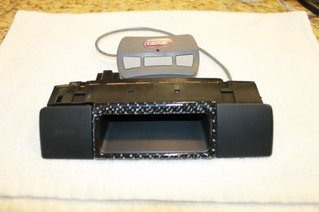
1. Remove the clock assembly by lifting the clock adjustmentcover and pull it slowly till you have the whole assembly out and be carefulnot to damage the tab and /or the cover.<o></o>
2. Disconnect theclock assembly plug.<o></o>
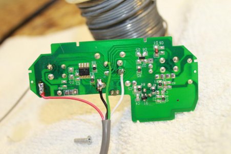
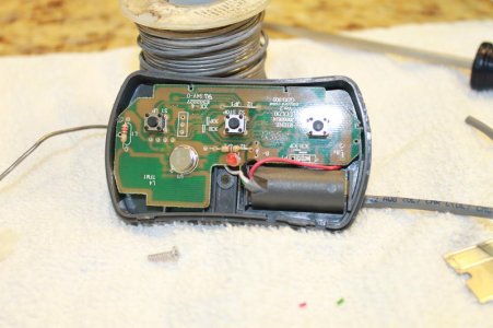
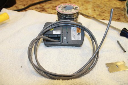
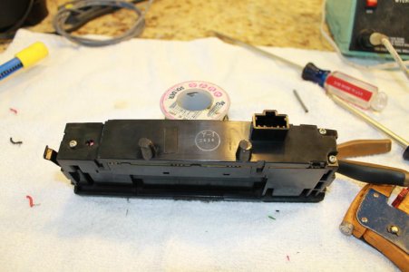
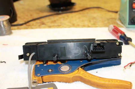
3. Now you need todisassemble your garage door opener by removing the screw and pry off the edgeswith flat tip screwdriver to expose the circuit board.<o></o>
4. Locate the batterytab you can remove it or leave it alone (I choose to remove mine). Note:Makesure you are using a garage door opener that utilizes 12 Volts Battery if notskip this step. Solder the both Ground (black wire) Positive (red wire). SeePictures.<o></o>
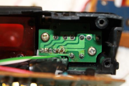
5. Next trace out theswitch tabs use a multi-meter to verify that you found the connections for theswitch solder both white and green to those tabs. See Pictures.<o></o>
6 .Once completed andverified reassemble your garage door opener.<o></o>
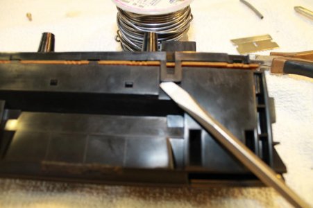
7. Now back to yourclock assembly: remove the 3 screws that secures the back panel and pry off the4 tabs that hold it in place be careful not to break them. I used tooth pick towedge and hold them in open position till I can get all 4 of the open andseparated.<o></o>
8. Once openedremoved the 2 screws that holds that secures the switch board. Be careful notto tip the clock assemble upside down or all the will fall off.<o></o>
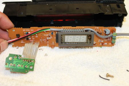
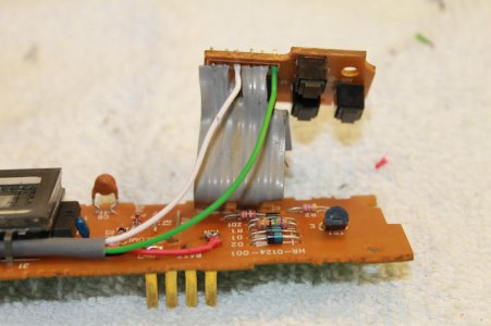
9. Disconnect theno.3 and no.6 on that flat ribbon wire for both switch board and main circuitboard. They are both labeled with number 1 and 6 .See Pictures.<o></o>
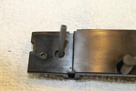
10. Make a small holeat the back panel of the clock assembly. Route the wire through it, and routethe remaining wire through the circuit board. See pictures.<o></o>
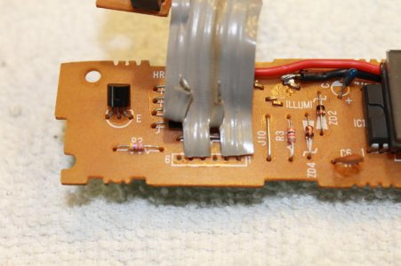
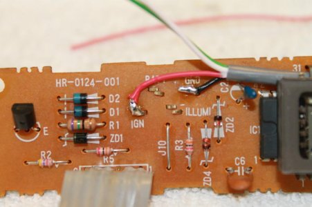
11. On the circuitboard locate the GND and IGN behind the plug prongs. Solder the black wire toGND and the red wire to IGN. See Pictures.<o></o>
12. Now solder thewhite and green wires to the switch board to flat wire no.3 and number 6. Seepictures.<o></o>
13.Re-assemble yourclock assembly reinstall the plug insert you key place it on IGN or position IIand test your Secret Switch...(make sure it is Programed to your garage door).<o></o>
<o></o>
Disclaimer: <o></o>
I am not responsible for any damage to your car orequipment. Perform this procedure at your own risk or hire a qualifiedtechnician if you feel that you don't have the capability or knowledge. Thankyou very much....and enjoy Christian….<o></o>
This procedure will show you how to disable the clockillumination button to be used as a different function like Fast and the FuriousDon's secret nitrous button, The Famous Ejecto Seato Cuz, or the one I choosegarage door opener.<o
></o><o
></o>1. Remove the clock assembly by lifting the clock adjustmentcover and pull it slowly till you have the whole assembly out and be carefulnot to damage the tab and /or the cover.<o
></o>2. Disconnect theclock assembly plug.<o
></o>3. Now you need todisassemble your garage door opener by removing the screw and pry off the edgeswith flat tip screwdriver to expose the circuit board.<o
></o>4. Locate the batterytab you can remove it or leave it alone (I choose to remove mine). Note:Makesure you are using a garage door opener that utilizes 12 Volts Battery if notskip this step. Solder the both Ground (black wire) Positive (red wire). SeePictures.<o
></o>5. Next trace out theswitch tabs use a multi-meter to verify that you found the connections for theswitch solder both white and green to those tabs. See Pictures.<o
></o>6 .Once completed andverified reassemble your garage door opener.<o
></o>7. Now back to yourclock assembly: remove the 3 screws that secures the back panel and pry off the4 tabs that hold it in place be careful not to break them. I used tooth pick towedge and hold them in open position till I can get all 4 of the open andseparated.<o
></o>8. Once openedremoved the 2 screws that holds that secures the switch board. Be careful notto tip the clock assemble upside down or all the will fall off.<o
></o>9. Disconnect theno.3 and no.6 on that flat ribbon wire for both switch board and main circuitboard. They are both labeled with number 1 and 6 .See Pictures.<o
></o>10. Make a small holeat the back panel of the clock assembly. Route the wire through it, and routethe remaining wire through the circuit board. See pictures.<o
></o>11. On the circuitboard locate the GND and IGN behind the plug prongs. Solder the black wire toGND and the red wire to IGN. See Pictures.<o
></o>12. Now solder thewhite and green wires to the switch board to flat wire no.3 and number 6. Seepictures.<o
></o>13.Re-assemble yourclock assembly reinstall the plug insert you key place it on IGN or position IIand test your Secret Switch...(make sure it is Programed to your garage door).<o
></o><o
></o>Disclaimer: <o
></o>I am not responsible for any damage to your car orequipment. Perform this procedure at your own risk or hire a qualifiedtechnician if you feel that you don't have the capability or knowledge. Thankyou very much....and enjoy Christian….<o
></o>Attachments
-
 IMG_5074.jpg55.7 KB · Views: 632
 -
 IMG_5075.jpg55.9 KB · Views: 587
 -
 IMG_5076.jpg61.2 KB · Views: 591
 -
 IMG_5077.jpg54 KB · Views: 585
 -
 IMG_5079.jpg44.4 KB · Views: 594
 -
 IMG_5081.jpg41.2 KB · Views: 580
 -
 IMG_5082.jpg52.5 KB · Views: 581
 -
 IMG_5083.jpg55.4 KB · Views: 585
 -
 IMG_5084.jpg51.3 KB · Views: 581
 -
 IMG_5085.jpg45.8 KB · Views: 590
 -
 IMG_5089.jpg42.3 KB · Views: 581
 -
 IMG_5090.jpg52.4 KB · Views: 601
 -
 IMG_5091.jpg35.9 KB · Views: 649


