• Protip: Profile posts are public! Use Conversations to message other members privately. Everyone can see the content of a profile post.

Need advice.. Making a custom N/A intake manifold

Joined
10 August 2006
Messages
761
Location
Ft. Lauderdale FL, Philly PA & Portugal
Need advice on runner/plenum lengths/dimensions/volume and general advanced design details for 6000-7000 RPM max power goals.

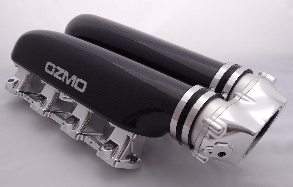
Ive been working on this experiment for a while.... and have modifed a spare OEM manifold to make a N/A custom Carbon fiber manifold and now plan on finishing this in next week or so.... The goal is to reduce 25lbs from the top most heavy section of the NSX, and hopefully gain 5-10whp in upper areas of power band through Reduced IAT's since fiberglass and/or CF have substantially lower thermal conductivity properties than aluminum and better mid-high RPM airflow design... Yes, the DMS manifold exists, it does not reduce thermal conductivity since its aluminum and it does not specifically focus on N/A power benefits.

using a skunks or blox 70-74MM billet throttle body and a pro-speed thermal intake gasket

debating on dual or single plenum, and/or to connect/round the end of the dual plenum to recirculate air
debating on focusing on mid to high RPM gain, but looking for more overall power "under the curve"
I'm willing to make 2-3 versions and test back to back on Dyno.

Some facts I've measured:

upper OEM manifold is about 130 ounces 3.8L
lower magnesium secondary manifold is 40 ounces 1.1L
(did not measure center butterflies section)

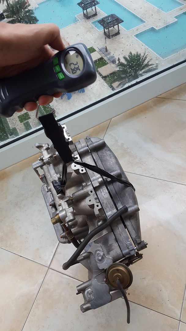
OEM manifold weighs about 23.5 lbs (see pic) with fuel rails and 21.5lbs without fuel rails
the OEM throttle body with all attachments is about an additional 10-11lbs
around 33-35lbs total

the finished assembly with throttle body goal is to weigh about 9lbs thus a 25lbs savings.


FYI. This not a business venture, not looking to produce these.
Yes my wife is pissed at me for working on this on the kitchen counter top and balcony. :)


examples of manifolds: https://www.google.com/search?q=por...h=829#tbm=isch&q=carbon+fiber+intake+manifold
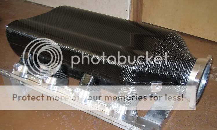


Last edited:
I applaud you taking this on.
I've read intake runner length, shape, and diameter are very important in achieving the velocity, turbulence and pulse wave intervals that create a "best" intake system.
It also sounds very complex with many variables all affecting the outcome.
That said, a 20 Lb plus weight saving is significant even without any improvements to intake flows.
Looking forward to reading about your progress.
 
after a few molds and allot of research and back and fourth with NA manifold designers tying to come up with a design that is build able


it starts off with the 70mm TB on a slight downward angle matching the inlet to reduce the bending of air then also slowly opens up the air tract to maintain velocity and also tapers to the last runners to compress the space and increase air speed with a venturi effect... there are also no hard angles anywhere inside the plenum all corners are curved to not create and inhibiting air pockets and keep air moving. all this this supposedly makes a big difference in air flow curves and also there is no way to see it here but the center of the 6 runners all have large velocity stack type bellmouths that "roll" into each other evenly.

worst case senario it saved 20-25lbs up high in engine bay and looks awsome and is unique. being saving weight at this point is costing me over $100 per lb lately . this may not end up being a bad deal.

hopefully it works.
the throttle body I am using is a b16 70mm that weighs 1.2lbs
so we are on target for a sub 10lbs total weight with TB and fuel rails in injectors.

let's see if it works :) wish me luck... should have it back from carbon shop in few days.
 
Last edited:
looks like a capon....:tongue:
 
looks like a capon....:tongue:

You be talking capon as in the rooster that sings in the soprano section? If so, you might want to check in to the cause for the six legged capons that you are seeing:smile: .

As to the manifold, it strikes me that it is going to have a fairly high profile. Any thoughts on arrangements for the air filter and cold air supply?
 
[MENTION=26435]Old Guy[/MENTION]

the air supply will be the oem airbox turned on its side which elevates the exit accordingly but retains the inlet in same location.

I may make a custom long tube intake pipe to suck air from the low pressure inside the fender towards to the rear of car similar to prospeed in future .

some people say it looks like an ardvark... lol.... any design will look like an animal since it needs legs, a body and a neck
 
Last edited:
Further to Stuntman's point engines don't suck in air.
When a piston is on a down stroke on the intake cycle, a lower than atmospheric pressure situation occurs.
Air outside the low pressure area is at atmospheric pressure and this pressure pushes air into the low pressure area to raise it to atmospheric pressure.
If the air pressure is slightly above atmospheric, such as at the base of a windshield, or a ram air type intake then more than atmospheric pressure can assist in pushing more air into the low pressure zone.
I think there is a bit of a ram air effect in the OEM intake as when at speed some air pressure should build up inside the vent opening helping fill the cylinders..

I beg to differ. Engines create vacuum, which creates the pressure differential that drives flow. So I think it's accurate to say that engines suck in air. Does a vacuum cleaner also not suck in air?

Having a higher pressure where air enters the intake will increase the differential and drive more flow, which I think is Billy's point. You may be right about the OE intake having some above-atmospheric pressure at its inlet but I would be surprised if it's significant.
 
I beg to differ. Engines create vacuum, which creates the pressure differential that drives flow. So I think it's accurate to say that engines suck in air. Does a vacuum cleaner also not suck in air? Having a higher pressure where air enters the intake will increase the differential and drive more flow, which I think is Billy's point. You may be right about the OE intake having some above-atmospheric pressure at its inlet but I would be surprised if it's significant.

Yes as I stated an engine creates a low pressure area inside the cylinder.
You call it a vacuum but it's no where close to a vacuum.
It's a simple low pressure area.
I agree there is a pressure differential created but the energy to drive the air flow comes not from a low pressure area in the cylinder, but from the 14.7 lbs per sq. inch of atmospheric pressure pushing the air into the low pressure zone.
Vacuum cleaners, lungs, syringes and engines all work the same way.

Atmospheric pressure will only push the water up 7 meters in a hand pump no matter how low the pressure is in the pump.
7 meters is the limit of the force of atmospheric pressure.

I agree with Billy and you that having higher pressure acting on an engine intake will push more air in.
That's the principle behind super and turbocharging.
But it's very difficult to consistently find greater than atmospheric pressure without mechanical help or very high speed.
I've read an F1 car with it's intake above the drivers head can develop as much as 5 % more power at 200 mph.

I think the most we can hope for at the intake opening is atmospheric pressure or maybe a bit more at speed.
My reading suggests optimizing volume and velocity of the air between the intake opening and the cylinder itself is quite a challenge.
 
Last edited:
...an engine creates a low pressure area inside the cylinder.
You call it a vacuum but it's no where close to a vacuum.
It's a simple low pressure area.

I suggest we use Wikipedia's definition: "In engineering and applied physics on the other hand, vacuum refers to any space in which the pressure is lower than atmospheric pressure." I said nothing about perfect/complete vacuum, I merely took issue with your statement that engines do not suck in air. Primarily, I took issue with you using it to criticize some else. On the remainder, we seem to agree.
 
there seams to be different theories in regards to this.
I run the oem air box now with downforce scoop and UNI filter as I ran them on dyno back to back compared to a cone filter and saw 2-4 whp gains... but one must take into consideration how quickly the uni filter gets dirty.. littlery just a few weeks and it turns black from road grime. and I'm sure the performance gain is lost if not negative to the cone filter in the engine bay using hot air mixed with some ram air pushed in by the scoop ... at least it's not clogging...

there is not enough room behind the fender scoop to install a sufficently large air filter with surface area to match the oem box and it will still get dirty quickly as well.

FWIW prospeed tested a couple variables and saw more gain with filter in the back of fender. I also see this a solution to keeping the filter cleaner longer. I've come across some other people with low pressure setups claiming more effictive intake velocity as well... it may be counter intuitive but it does not hurt to try it out. we all know ram air appears to be myth that as no effect at the max 120mph speeds we experience.

it's one thing to set up something that performs well on dyno day one which what most of the current setups appear to do.... it's another thing to come up with something that works well for a longer period of time by staying clean.

regardless, I will use/test this thing with the current oem box and uni filter and scoop first and then experiment from there


so far the CF manifold itself is weighing in at 570grams = 1.2lbs, so it s still under the 10lb goal including the 6.6 flange & fuel rails and the 1.2 lbs TB :)
 
Last edited:
we should not pray to false idols made of carbon .....:tongue:
 
Taking air for the engine from a low pressure area is a pretty flawwed fundamental idea. Look at any racecar, they all take air from high pressure or free stream areas which improve an engines intake efficiency and is not a myth, but its not going to give you 10hp at low speeds either.

Go play with a manometer at various places on the car. After all this work you're doing on the intake, it seems counter productive to source air from a low pressure area...

0.02
 
Last edited:
[MENTION=4282]docjohn[/MENTION]
lol

[MENTION=5905]JD Cross[/MENTION]
thanks!

[MENTION=16531]stuntman[/MENTION]
I agree it does not make sense, thus why ive mentioned its being designed to work as-is with oem box and scoop now, but theirs nothing wrong with tinkering with the location of optional filter location set up later.
the main problem with the current layout is whenever i open up the filter box there is a softball sized circle of dirt off the center of the UNI filter, this is obviously the preferred flow path the air wants to go through and that particular area gets dirty very fast even tough the rest of filter is clean. many people have complained about this problem.

I'm going to try this later anyway, maybe there is high enough pressure back there, since it is fed by the same air inlet and the fender well shape its self may act like a scoop in its self.
this is pretty easy to try out anyway, wont be a big deal if it does not work.
FWIW: there was a few supposed benefits of the rear location, longer intake tube and ability to run a filter with incorporated bell mouth.
http://www.nsxprime.com/forum/showthread.php/162460-PROSPEED-NSX-Cold-Air-Intake-System

Another idea: if not in the rear of fender, maybe in same oem fender vent location i can try a long cone filter with a shield blocking debris from hitting it and maybe close off the rear section of the fender above the tire, basically to turn the front part of the fender into a large high pressure airbox.
 
Last edited:
Pics of the softball sized dirt circle?

There is no airflow on a static dyno to cause a low pressure area behind the rear wheel. This yields similarly false results like a "hot air intake" open air element filter making power on a dyno with the hood open, sucking in ambient air, when it greatly reduces power bybsucking in hot engine bay air when the hood is closed under actual driving conditions.

I don't really like the design of that prospeed intake...

Are you taking about the side inlet/intake/scoop? A "Vent": is an opening that allows air, gas, or liquid to pass OUT of.
 
[MENTION=16531]stuntman[/MENTION]

just took some pics as requested, i even rubbed my finger on it to show show thick and grimy it is in the middle... this has been documented on prime before its absolutely horrible, this is with just a few hundred miles on it.

yes i was referring to the vent in the fender where the scoop goes, (see quick hand drawing) :) i think an ideal setup may be a long cone filter in place of the scoop with a small shield protecting it from direct hits of water and grime instead of direct ram air (to keep it clean) if the fender well is blocked off at top of the fender arch to maintain high pressure in front area of fender and the fender area itself may act as somewhat of an air box

also FWIW including pics of the huge BPI velocity stack bell mouth I attached to the air box entrance mouth, I installed this while on the dyno FWIW without moving the car and we confirmed a 2-4rwhp gain through out, while I'm explaining little things I've done over the years. also eliminated the crappy flex tube between the intake and TB and installed a vibrant reducer instead.


<a href="http://s172.photobucket.com/user/tiago3/media/20151221_204818.jpg.html" target="_blank"><img src="http://i172.photobucket.com/albums/w15/tiago3/20151221_204818.jpg" border="0" alt=" photo 20151221_204818.jpg"/></a>
</center>
 
Last edited:
just took some pics as requested, i even rubbed my finger on it to show show thick and grimy it is in the middle... this has been documented on prime before its absolutely horrible, this is with just a few hundred miles on it.
Given the location of the airbox inlet and the angle of the air filter, that grime pattern is to be expected. Who else has had this problem? Maybe its just a florida thing...

Have you tried a K&N filter element or a dry filter? Keep in mind the surface area of a panel filter is far less than a cone type filter.

yes i was referring to the vent in the fender where the scoop goes, (see quick hand drawing) :)
It's a scoop, not a "vent" ;)

i think an ideal setup may be a long cone filter in place of the scoop with a small shield protecting it from direct hits of water and grime instead of direct ram air (to keep it clean) if the fender well is blocked off at top of the fender arch to maintain high pressure in front area of fender and the fender area itself may act as somewhat of an air box
Yup. As long as its air tight.
 
FYI... The throttle action on a blox TB is not really that great. Sometimes even the butterfly has a tendency to get stuck or stick near idle. The spring tension and throttle opening ratio is also different (to put it nicely). Just hope you've considered this. It will change your right foot's relationship with the gas pedal. In my experience, I didn't like it at all.
 
[MENTION=20915]RYU[/MENTION]
thanks for the info!
I was not aware of that... no worries I'll find something that works of not happy with it.. can esily modify it to take different TB's.. do you have a better recommendation?
[MENTION=16531]stuntman[/MENTION]
thanks for info and feedback as always
I'll make sure to call it a scoop. :)

not sure who else specifically mentioned the dirty filter when using scoop but am sure have seen it mentioned on prime more than a few times over the years.
 
Last edited:
yes downforce scoop has been inside fender since right after I bought the car 9 years ago. I think it was my first mod. :)

actually the scoop now is centered and pointed one inch away from the velocity stack entrance which sucks in a mix of fender air and rammed air. the velocity stack is technically being accelerated by the forced air... this is my theory... who knows.... lol....

but FWIW the filter has always gotten that dirty quickly even before my velocity stack mod.
 
Last edited:
Back
Top