• Protip: Profile posts are public! Use Conversations to message other members privately. Everyone can see the content of a profile post.

Cruise control "set" wiring help!!

Joined
10 March 2012
Messages
503
Location
New Bern, North Carolina
OK, so I have my aftermarket steering wheel and have my horn hooked up according to this diagram. It runs from the harness under the dash up to the horn button where it grounds out and it works. I did the same with the cruise control "set" connection and it isn't setting my cruise control. Is there something I am missing? Thost sections of the harness look like they all combing and end at a positive yellow wire. Is that what needs connected to pin 2 to set the cruise?

I feel like this is one of those obvious answer things and I am just not seeing what it is. What have others done in the past to maintain the cruise set control without and factory wheel and buttons?

Thanks in advance

-Alec

attachment.php
 

Attachments

  • harness.jpg
    harness.jpg
    52 KB · Views: 460
Hi, Alec.

In your diagram, #3 is the 'SET' and #2 is the 'RESUME'.
Looks like the pin assignment in your diagram is not correct….

#1 in your diagram is the high level signal so you could install the 'SET' switch between #1 and #3 depending on the position of your 'SET' switch.

That's what I did.
http://www.nsxcb.co.uk/entry.php?1419-KSP-ABS-Upgrade-Loom-Cruise-Control-switch-02

For the same reason, installing a switch between #1 and #2 will enable the 'RESUME' feature.


Depending on the position of the SET/RESUME switches or if utilising the existing OEM ones, you could just use high level signal nearby.

All you need is the high level signal into the ‘SET’ terminal at the Cruise Control module behind the glove box (non-DBW) or at the ECU behind the right side seat (DBW).


Kaz
 
Thanks Kaz! So I need to connect pin #1 to pin#3 to just have the set function. That's really weird. Grounding out pin #1 is setting my horn off. Is that how thats supposed to happen?! I found that diagram on prime, but this would explain why it wasn't working.

-Alec
 
You need to put your SET switch between the #1 and #3 pins.
When the SW is pressed, #1 and #3 will be shorted through the switch. By the way, it has to be momentary sw otherwise your set speed will be reduced continuously.

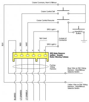
The diagram you had is for some sort of aftermarket parts/wiring/device so it has extra wire.
Also inside the OEM steering wheel, there are extra wires for the horn and cruise control switches but since you have removed it for the aftermarket installation, you need to create similar thing
As mentioned in my previous post, you can use #1 as the high level signal to trigger the SET feature or you can use nearby 12V depending on your actual SET switch location inside the cabin.

As you were referring to this 6pin yellow connector, I believe your aftermarket steering wheel requires you to remove the cable reel on installing the steering hub/boss.

With OEM setup, at this 6pin yellow connector, #1 is always at +B (battery power) and it’s the low side of the Horn relay coil circuit. Therefore, if you short #1 to the GND, it will activate the horn relay and thus, it will trigger the horn.
Your horn switch on the steering wheel creates the short circuit to the GND through the steering boss (for aftermarket installation) or the extra wires behind the SRS module (for the OEM steering wheel).

+B - horn relay - #1 pin - contact plate behind boss or one side of horn sw - horn sw - boss body (GND) or nearby GND depending on the type of your horn sw.


This #1 pin is also shared by the SET and RESUME switches as the high level trigger signal for the cruise control.

+B - horn relay - #1 pin - SET sw - SET terminal (at Cruise Control unit or ECU)


You will get better idea if you look at the workshop manual and look for the horn and cruise control circuit diagram.
Also, if you look at my installation process, it will provide you with extra info.

http://www.nsxcb.co.uk/showthread.p...teering-wheel-with-OEM-boss&p=58209#post58209


Kaz
 
Back
Top