• Protip: Profile posts are public! Use Conversations to message other members privately. Everyone can see the content of a profile post.

Clock Mod

Joined
1 October 2006
Messages
2,738
Location
Memphis TN
I modified the clock to show wideband AFR.


Zeitronix Zt-3 wideband with the Hacker/Tweaker display mounted in the clock housing.
Fairly inexpensive mod at $209 for most everything, about $50 more if you don't have a O2 bung welded on.

Mike


Last edited:
Not very hard to do this mod.

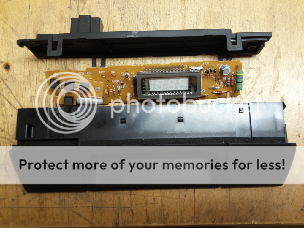
When removing the clock use a non metal tool to release the clips on both sides to keep from marring the finish on the console . If all you have is metal the clock can be removed by pulling on it while prying slightly from underneath the clock above the vent (how I do it). There are a few screws on the back of the clock and four tabs. After getting it apart you remove two screws behind the clock buttons and it all comes apart. The clock board is held to the back piece only by the pins for the plug which pull right apart.

Mike


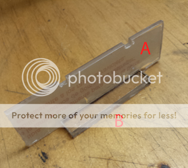
I made my pieces a little wider from side to side then needed but the wider they are the tighter it will fit together

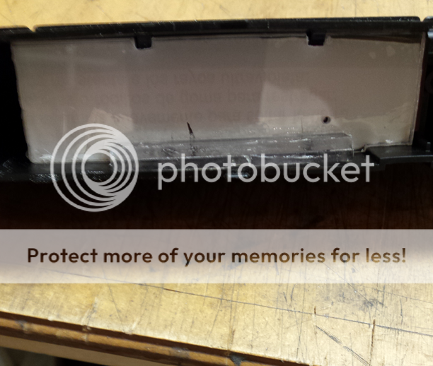
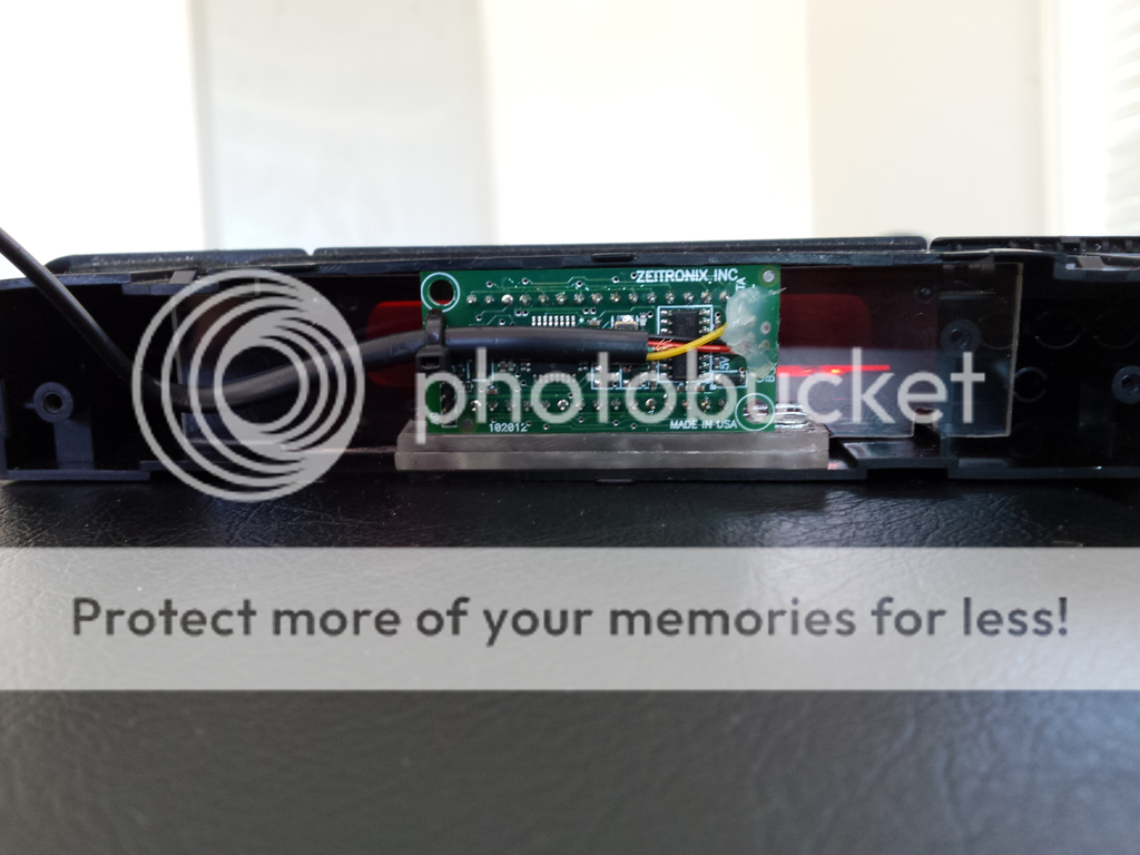
For "A" I used a 7/64" piece of acrylic but DO NOT remove the protective paper until your final assembly to keep from getting glue on it. It does two things, it protects the red lens of the clock from being scratched by the display and positions the display where it's all seen through the opening. It's just cut as a rectangle and notched where needed to fit completely against the clock lens. This needs to fit tight in the housing where it will stay on it's own. For "B" I epoxied a few pieces of acrylic together (2-7/16 & 1-3/32) for a total of 19/64. You can do this with any plastic to come to that thickness but that is about the max it can be. This piece raises the display to the topmost position in the housing where it can be seen through the opening and should go all the way to the back of the housing. I epoxied B to A at the very bottom. The display fits tight in the housing with the circuit board sitting on B. After fitting the display in the housing I applied 1/4" foam rubber to the inside of the back panel and snapped it back on. You will have to make a small notch in the back cover for the display wire to come out but other then that everything can go back to OEM if desired.


The standard kit comes with a 10' cable for the O2 sensor which if installed in the rear bank gives you enough cable to reach behind the glove box which is where I mounted the ZT-3. It would probably reach from the front bank but I chose the rear because it's more out of the way. I routed around the engine compartment on the passenger side and through the rubber grommet behind the passenger seat. From there I routed under the carpet to behind the glove box. For the power ground I routed back to the AEM along with one lead that connects for data logging. The ground only needs to ground near the AEM when it's connected for data logging otherwise you can ground anywhere. I suggest DON'T CONNECT the +12v to the original clock power. It can be run to the fuse panel and connected there. Mine is connected to IG2 which means the gauge comes on with the key in ON or START. If you connect IG1 then when you turn the to ON position the gauge will turn on and when you go to start it will go off till the engine starts and come back on. By connecting to IG2 it gets powered when you switch to ON and then never goes off until you cut off the car.

Mike
 
Last edited:
Haha I am not but we can still be Nsx brothers!

I switched over to the dark side and have model 5's and ce28's...

NSX brothers works for me, in fact it's an honor :)

The force is still strong in this one :biggrin:.
Ah, the group keeps getting smaller, I may be the last one.


Message me on FB if your on there, just Mike Davis
 
I opened the clock back up today to take some measurements for someone. So I got the chance to take a fitted picture.

Mike


Back
Top