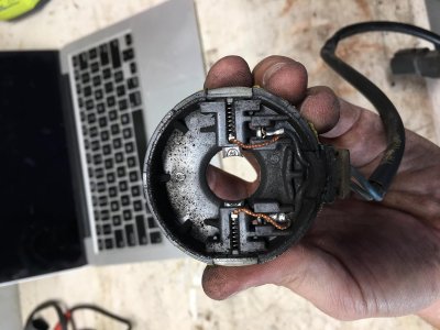
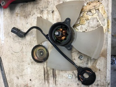
After some troubleshooting it appears that I have 2 dead AC Condenser fans. They're $250 each from Acura, so I have one of them out and torn down on my work bench.
1. It appears that those brushes need to be replaced. According to calipers they are .23" or 5.8mm square, but I don't know the length. Can I guess an approximate length and be ok?
2. What else should I do while I have this motor torn apart? Cleaning, oiling, etc.
Speak slowly and use small words, this type of repair is new for me =)
Thanks!
EDIT: In this thread about a seat motor [MENTION=7701]Oldguy[/MENTION] says to see if the commutator is worn down, check to see if the windings are ok, and that there isn't bridging int he commutator segments. How can I do these things?
Attachments
Last edited:


 I've no idea what went wrong but the fans MUST work the opposite way. Are you sure it blows out of the bumper and it's not vacuum you feel? Try with a candle.