• Protip: Profile posts are public! Use Conversations to message other members privately. Everyone can see the content of a profile post.

Tuning the NSX 3.0L Using the OEM ECU

Joined
27 July 2007
Messages
7,453
Location
Denver, CO
Continuing the discussion over from the cam thread.

I am not really familiar with the CT stuff. I had assumed that IEM refers to Intake, Exhaust, Muffler - bolt on stuff which usually has a minimal effect of volumetric efficiency. If CT limited their head modifications and camshaft such that it would operate acceptably with the OEM ECU, then you are probably OK to do the resistor snip on your auto ECU and run on the manual fuel maps. Peak horsepower at wide open throttle usually occurs when the fuel map is set to give an AFR around 13 (or a nudge less) at the RPM & MAP corresponding to peak power. At wide open throttle the OEM ECU is in open loop and probably runs the engine significantly below an AFR of 14. If the CT package raises the VE and you leave the fuel map as is, the resultant AFR must go up. However, perhaps CT limited the VE improvement in the cam / head / IEH package such that the AFR would not become risky (higher than 14.7). All they did was eat into some of the margin that Honda provided in the fuel map. It means that they likely left some horsepower on the table; but, were able to market the package to a larger range of customers (because aftermarket ECUs were not so common in the early '90s). The up-side for you is that simple tuning of the fuel map may yield additional horsepower.

Wideband O2 sensors- yes & no. I was thinking of adding WB sensors in the manifold in addition to the OEM NB sensors by welding in extra bungs. The WB would just be for monitoring AFRs. The ECU would continue to run off the OEM NB sensors. You cannot plug a WB sensor into the OEM ECU for a lot of reasons. The OEM ECU lacks the controller required to operate a WB sensor, the output slope is inverted and .... on and on. What some / most aftermarket wideband controllers allow you to do is emulate a NB sensor. The controller will have two outputs. A WB output to drive an AFR gauge and a simulated NB output that you can connect to your ECU. In theory this allows you to replace your existing OEM NB sensor with a WB sensor and get two outputs. Problem is the theory does not always seem to work so well. You may want to ask around to see if anybody has done this successfully. One of the obvious problems to me is that when you ditch your heated narrow band and just provide a voltage signal to the ECU, the heater monitoring circuit in the ECU is connected to nothing and will throw a code unless you can fake the heater circuit some how.

Check out Sparkfun and Adafruit. One of them had some good tutorials for replacing high pin count devices - usually SMDs.

Fuel trim is probably not a term you would find on TunerPro. It would probably be described as fuel correction or exhaust gas O2 sensor correction and may or may not be displayed. Trim, or fuel correction or EGO correction would typically be displayed as the % correction to the fuel map value required to bring the actual AFR to its target value - which on an OEM ECU will be 14.7. This begs the question, when you rewrite the fuel maps on the OEM ECU, are you only rewriting the fuel maps in the portion of the maps that correspond to open loop control? If you are in closed loop control with the narrow band sensors you only have one option and that is to run at an AFR of 14.7.

So I spent a lot of time researching this last night. Lots to unpack.

First, as best as I can tell, the Comptech IEM ("Internal Engine Modifications") package included the following items: (1)Comptech Camshafts; (2) 36mm "de-shrouded" intake valves; (3) "light" port and polish of the heads; (4) Comptech valve springs (Eibach); (5) milled heads to slightly increase compression; (6) intake seats re-ground to fit +1 mm valves. At some point early in the life of the product, Comptech also was milling the valve spring pockets deeper and using the factory Honda springs. This became cost prohibitive and they switched to using the Eibach springs, which are a stiffer rate and did not require head machining. Per docjohn and greenberet, the package was plug-and-play, e.g., it did not require any changes to the ECU to run properly.

Based on my research, and setting aside ignition timing for the moment, the NSX OBD-I ECU runs in three different fueling "phases": (I) Cold Start/Idle Open Loop; (II) Warm idle/Part-Throttle Closed Loop; (III) High load/VTEC Open Loop. In closed loop operation, the ECU receives signals from the two narrowband O2 sensors and continually adjusts the fuel amount (via pulsewidth adjustments to the fuel injectors and/or fuel pressure) to achieve a "perfect" mixture ratio of 14.7:1. 14.7:1 is ideal for emissions and delivers the best performance from the catalytic converters, it also ensures a complete burn of the fuel, clean engine oil and a clean combustion chamber. However, this ratio is not ideal for performance and results in a VE that is lower than what the engine is capable of. The ECU's fuel trim adjustments are expressed in two variables: BLM and INT. BLM (or, Block Learn Multiplier) is the long term fuel trim value. This is the value that is "learned" and stored in the ECU's volatile memory, and which is erased if you pull the clock fuse or otherwise disconnect power to the ECU. BLM can be anywhere from 0 to 255, with the ideal number being 128, which means that no fuel changes are needed and the AFR is at a perfect 14.7 for that load state. A BLM below 128 means that the mixture is too rich in that load state and the ECU will reduce fuel to lean it out. A BLM higher than 128 means the opposite- the mixture is too lean and the ECU will add fuel to enrich. "Long term" is really in the context of computer time- the BLM is updated every few seconds. INT (or, Integrator) is the short term fuel trim value, which is adjusted many times each second based on signal from the O2 sensors and is not stored in the ECU. INT also is between 0 and 255 with 128 also meaning that no fueling changes are required. On cold start, INT is locked at 128 to ensure that the ECU will not make any changes to fuel until the O2 sensors are warmed up. Once the engine goes into closed loop, INT will change as the O2 sensors report back on the AFR. If the mixture is lean, INT will go above 128 and the ECU will begin increasing the injector pulsewidth. If the lean condition persists for a few seconds, BLM also will go above 128. INT "drives" BLM back toward 128 from either direction. If the engine moves to another load state before INT can correct the mixture, BLM acts as a "reference book" for the ECU so that if the engine returns to that load state again, the ECU will already know roughly how much fuel to add or subtract. This is the "learned" fuel trim function of the OBD-I ECU. It works very well, but it also GREATLY complicates engine tuning.

In open loop operation, the ECU ignores the signal from the O2 sensors and references a simple lookup table to determine how much fuel to add to the mixture. This seems simple, but a complicating factor is that apparently, the ECU will reference the highest load state BLM value and apply it to all cells in the open loop table! I have to investigate the NSX tables, but generally speaking this means the following: lets' say that the high cell BLM value is 135. This means that right before the engine moved out of closed loop, the best information available to the ECU makes it think that the mixture is 5.5% (135/128) too lean at that load state and it should add fuel. Thus, when you stomp on the gas and go into VTEC, it will apply a 5.5% multiplier to all load states in the open loop table. Assuming you have already tuned the open loop table with a wideband O2 to have a "perfect VE" AFR (usually somewhere between 12.5 and 13), your mixture will be 5.5% too rich across the powerband. You won't be getting maximum power out of the tune. This is frustrating, but otherwise ok for lean BLM values, since the engine will be running on a safer, richer mixture. Where it gets sketchy is if the BLM is in the rich range (i.e., lower than 128) when you step on the gas. Here, the ECU will pull fuel and lean out your mixture! Not ideal at WOT, as it could potentially result in dangerous conditions inside the combustion chamber. So, the prevailing wisdom appears to be to set your open loop fuel maps slightly on the rich side as a safety margin in case the ECU pulls fuel due to the BLM values.

As for how to tune, there seem to be many options:

OPTION 1 - TUNE OPEN LOOP ONLY -- Option one is to leave the closed loop operation completely alone. Even with the IEM heads, header, exhaust and ported intake, the ECU will still be able to get the car to 14.7 during closed loop. Instead, you focus on tuning the open loop fuel map to hit that magic 12.5-13 sweet spot, using a secondary wideband O2 sensor installed on one of the manifolds, like Old Guy suggested. I think this is what most aftermarket tuners do. To me there are two issues with this method. First problem is if you change injectors. The entire closed loop feedback system assumes the ECU knows how big the fuel injectors are so it can know how much fuel to add or subtract. If you install larger injectors, you will alter fueling across the entire map because the ECU will still command a certain pulsewidth, say 4 ms, but a RDX 410cc injector will deliver more fuel over this time period than the OEM 240cc. Thus, while the ECU still my be able to deliver 14.7 AFR in closed loop, we likely would see bigger "swings" around that number as the ECU over-fuels, realizes it is too rich, then drastically pulls fuel to correct. Real datalogging would be needed to confirm this, of course. Second problem is that you're leaving a lot of performance on the table, since you would not tune the closed loop sections of the map at all (though the base fuel map may influence the closed loop trims- still to be figured out)

OPTION 2 - TUNE OPEN LOOP AND CLOSED LOOP -- Option two is harder, because you have to figure out a way to tune closed loop operation in a way that the ECU will "chase" a more favorable AFR for performance instead of 14.7, which is best for emissions and fuel economy. As discussed briefly above, my research has indicated that the base fuel map does have some influence on closed loop operation. We would have to figure out the mechanism for this in the NSX ECU, but it may be that the base fuel tables give the ECU a baseline to set BLM and INT and then adjust off of that based on the O2 data. It would be interesting to now if the base tables continue to influence BLM and INT as the O2 sensors are reporting back. Maybe as a multiplier? But, even if we figure all that out, the ECU is still going to adjust fuel to get to that 14.7 mark, thus negating your cams and headers and all of the other performance parts you spent money on- at least in closed loop. Forums like pgmfi.org and others have members who vaguely reference a "BLM tune" with the implication that you can alter the BLM data (e.g., BLM = BLM * 1.05) in the ECU so that the ECU will think that the mixture is leaner than it really is and add fuel. I have no idea if this is even possible, considering I cannot even find a BLM table in the NSX definition. This may be something that only appears in a datalog and there is no .adx file for this definition (another issue we will have to tackle). A more elegant solution may be to alter the voltage table for the O2 sensors. After all, the ECU does not see AFR, it sees voltage, which it converts to a data point. The ECU code tells it to chase the data point, not 14.7 AFR. If we change the table so the the voltage describes a mixture that is leaner than it actually is, the ECU would chase a richer mixture across the entire closed loop function. We would have to tune this with a secondary wideband. I also have to find the table or scalar for the O2 sensor voltage in the definition.

OPTION 3 - TUNE OPEN LOOP AND SHRINK CLOSED LOOP -- When you think of closed loop, it actually makes sense in a way. When you're tooting along on the highway at 70 mph, 3,000 rpm and 10% throttle, you don't need tons of power. You don't need that 12.5 AFR and, in fact, it's better to have 14.7 because it will keep your cats, oil and combustion chamber clean. It's only when you downshift and step on the gas to pass that you want to have that power bump that you spent thousands on in parts to achieve. Honda tuned the fuel and timing maps to accomplish this, but they also had emissions requirements, so they probably placed a lot more of the map in closed loop than you really need for clean highway cruising. So, maybe a better solution than #2 is to fully tune the base open loop maps, leave closed loop alone, and "shrink" the area of the maps that would fall under closed loop. I'm still looking for the scalars and/or tables that would control this for the NSX. I think this is a more elegant tuning solution and if it is possible, I think this is the direction in which I want to go.

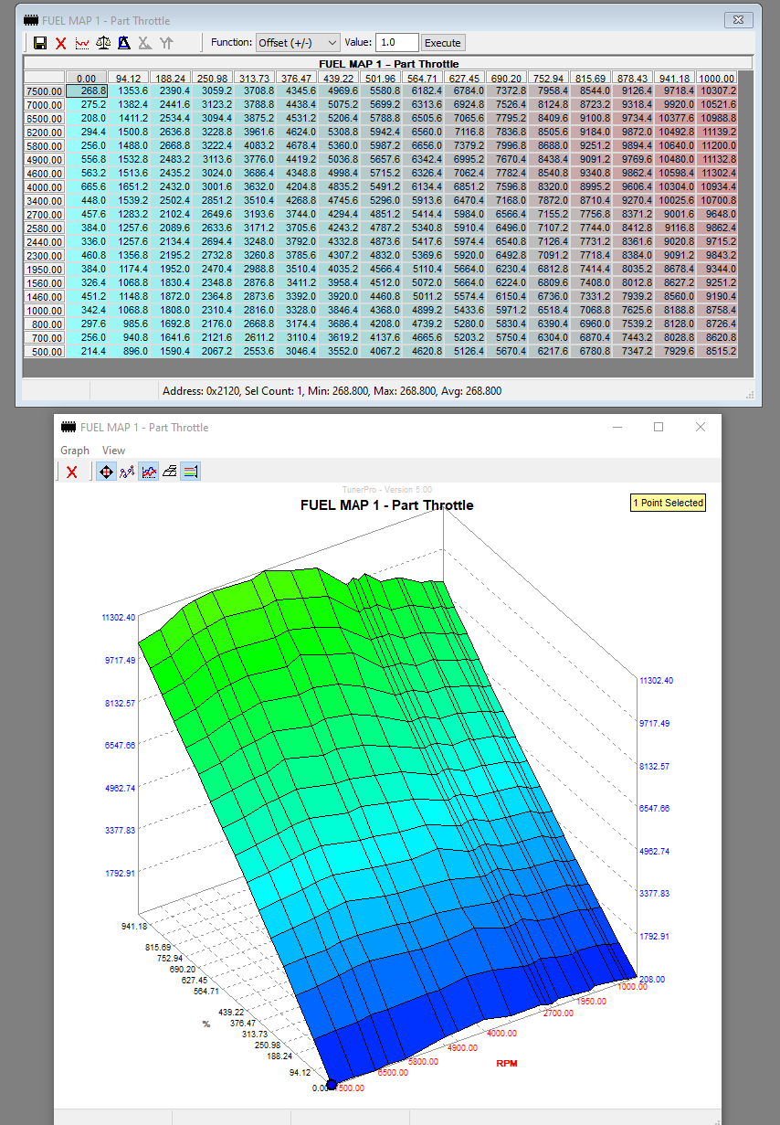
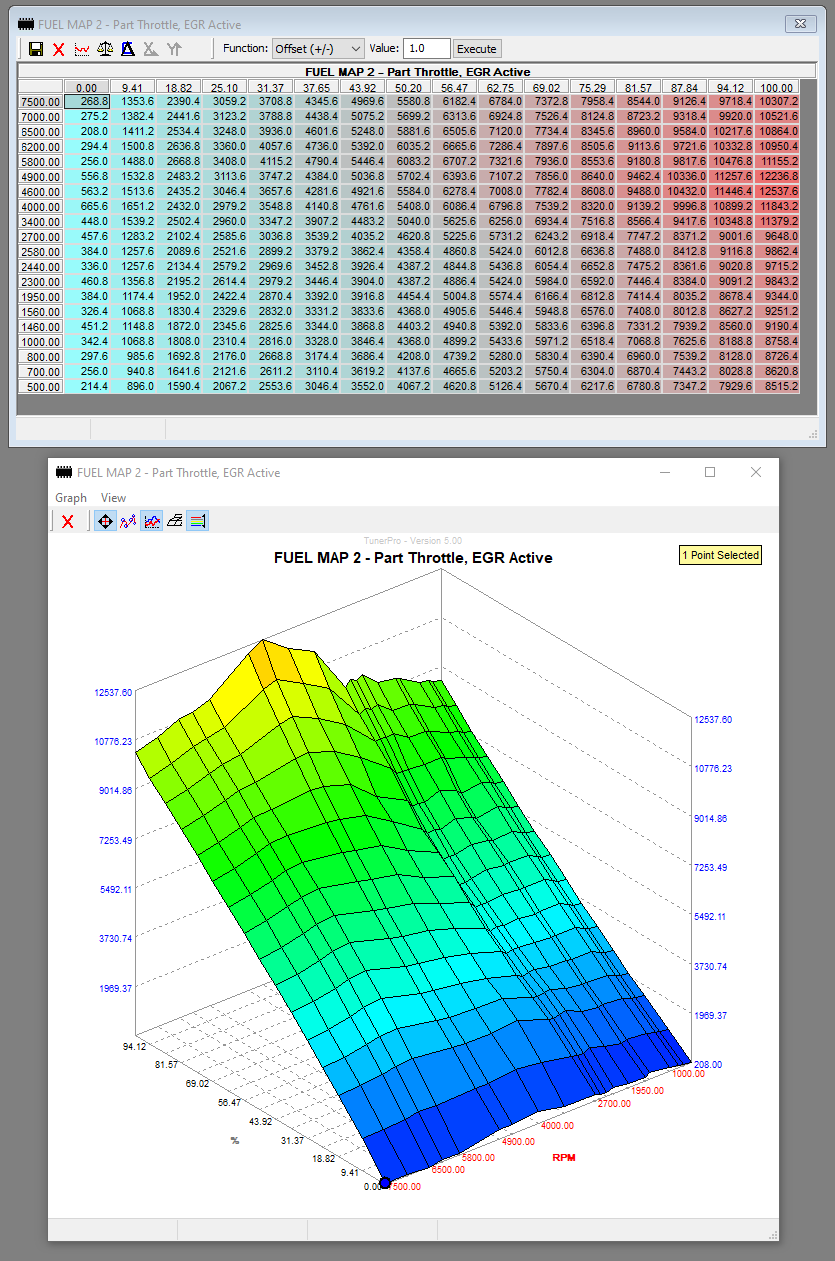
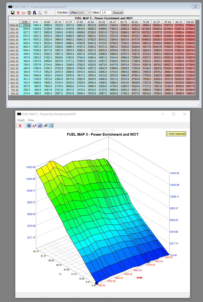
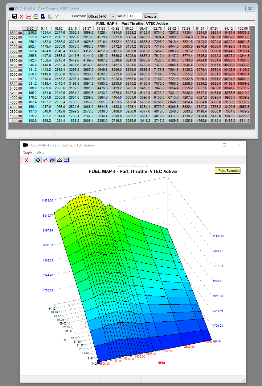
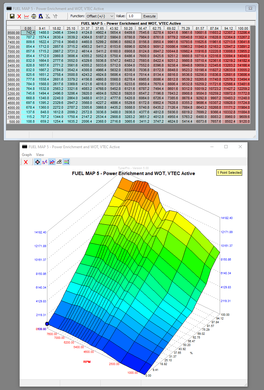
I am going to install TunerPro on my desktop tonight and start poking around the NSX definition to get an idea of how the ECU maps correspond to the above conditions.

[MENTION=26435]Old Guy[/MENTION]
[MENTION=12356]Mac Attack[/MENTION]
[MENTION=20915]RYU[/MENTION]
[MENTION=16606]sr5guy[/MENTION]
[MENTION=12723]greenberet[/MENTION]
[MENTION=4282]docjohn[/MENTION]
 
Last edited:
TL;DR

If you would like my help feel free to ask me specific questions, all I see is two text walls of assumptions.

-Matt
 
I'm on the journey with you.....:smile:
 
I look forward to this thread!

Matt, do you have a definition of the NSX's PGM-FI that allows the maximum rpm of the engine to be adjusted as well as the rpm at which the VVIS changeover occurs?

My gut feel is that a datalogging capability for the PGM-FI would allow a better tune to be developed but as discussed with Matt in the past, that would require him to make physical changes to the PGM-FI unit so that a datalogger could be plugged in. Matt, would you potentially be interested in doing that as a service for NSX owners in some fashion?

Honcho, regarding the Comptech IEM: that did not include 36mm intake valves, at least not in the winter of 1994/95 when I bought their IEM package. Regarding the ECU, Comptech were offering a "Comptech engineered Performance Chip". They told me that I could get more horsepower if I spent more money and had a chip custom-programmed instead, so that's the route I took. How good of a job Autothority really did custom programming a chip with my car on their dyno is a different issue.
 
TL;DR

If you would like my help feel free to ask me specific questions, all I see is two text walls of assumptions.

-Matt

Thanks Matt. Yes, I'm mostly posting general EFI theory as a baseline and then hope to apply it directly to the NSX OBD-I ECU. I'm doing this thread as a reference for others in the NSX community who may want to lend a hand or effort. I can't thank you enough again for the huge amount of work you put in here. Hopefully we can refine the definition even more and get to a tuning solution, which is the point of this thread! I spent last night poking around the NSX .bin and have a few specific questions:

(1) There are .bin files for a PR7-A03, 91MT and 94MT. Which one is the "universal" .bin, if any? I've been working off of the PR7-A03 file because I assumed that was the one you cracked.
(2) We know (thanks to you) that snipping R4 on the board reverts the ECU to another section of the EPROM, which contains the manual transmission data. I noticed a Flag in the definition that was called something like "AutomaticManualSwitch". Is this a virtual method of snipping the R4 resistor? By default it appears to be not set.
(3) Similar to the above, I noticed two groups of fuel maps in the tables. They appear identical, though I have not fully compared them yet. One set is at the beginning of the tree and another set appears further down the tree. Are these the Manual and Automatic maps? Or, are these just two copies of the same maps?

I'm on the journey with you.....:smile:

:encouragement:

I look forward to this thread!

Matt, do you have a definition of the NSX's PGM-FI that allows the maximum rpm of the engine to be adjusted as well as the rpm at which the VVIS changeover occurs?

My gut feel is that a datalogging capability for the PGM-FI would allow a better tune to be developed but as discussed with Matt in the past, that would require him to make physical changes to the PGM-FI unit so that a datalogger could be plugged in. Matt, would you potentially be interested in doing that as a service for NSX owners in some fashion?

Honcho, regarding the Comptech IEM: that did not include 36mm intake valves, at least not in the winter of 1994/95 when I bought their IEM package. Regarding the ECU, Comptech were offering a "Comptech engineered Performance Chip". They told me that I could get more horsepower if I spent more money and had a chip custom-programmed instead, so that's the route I took. How good of a job Autothority really did custom programming a chip with my car on their dyno is a different issue.

There are several RPM limiter scalars in the definition. Here are a few:

t8wSpihikYYNNp8Pu1hLv-o4owuhZIrwoQN1wKC81puwgu_E4KBwoYjEl6f13qoqmTEw6Vi9An44S3kMFrd5SIgKF2Lh6mxcIss7cNjTxv63BRlamzhQiXw4bj58QtcUogGvRqnzSgbiB7l-w_SedN3fHT2r5us6PHNEPGw-RsRfCDC4nPtSxD3pXN2iUnKqQuNwZ21QlbodHcz4ZxOINcIyAdN4sDqXcRLYxJ97LBr9CFfwvzi1W51VuK2g_YCdK-Ua1wDahNDihxB0-Dhd9yY2poVhRrR-P0T5K_P0xDpr_Dh27dJHy1Yz93pHtP_7ysx0yr3l2dg-W2QOLhbwTXSpbbYDoniXfaKMdXWvzszyXIdLDer-4HmKpuxuhmHb71T_SIXioZkfrEe_EXCagklmHMVhdTOOOnsAh-8LFL2NZdQzY7wPdsoNeswAw_krJYIT4ii-iSOFPsgFfmxySZtuaE7sks1ibkizGK1sDzQiXyeRiqbgHUEpBy18HYcWsUHLQQ0UU204Ibu5kSJo2mBdnhFjxbGC5NCNziy_5Mz0KTf9aKdKi98OWnKb4MULJYCc9JQHO8wKpgYgbbd3NlM0N1hfZw3I8O9dP9AwYpZp9-HytZNTuhb7bepqMt0b8yu4G1mpGIwyaFKiuvLAU9rDshgvLSx66DSO9GnKszAUOWXo1_VRSDg=w1250-h171-no


What is odd is that the main RPMLimiter appears to be set at 7,000 rpm. This makes no sense, as the factory service manual is clear that, for the manual transmission, the RPM limiter is 8,000 rpm with a fuel cutoff at 8,300 rpm. Also, I'm pretty sure "CTS" means Coolant Temp Sensor, but a threshold of 244 degrees makes no sense if in Celsius. Maybe more if it is Fahrenheit. Even stranger is I could not locate any fuel cut scalar. There has to be one.

Also, I measured the Comptech intake valves from my heads with my dial calipers and they are 35.99 mm. They also have factory stampings on them, which leads me to believe they are OEM NA2 valves. They don't look "de-shrouded" to me. Docjohn must have bought this in 1997 or later.
 
Last edited:
What is odd is that the main RPMLimiter appears to be set at 7,000 rpm. This makes no sense, as the factory service manual is clear that, for the manual transmission, the RPM limiter is 8,000 rpm with a fuel cutoff at 8,100 rpm. Even stranger is I could not locate any fuel cut scalar. There has to be one.

Doesn't the service manual states fuel cutoff at 8,300 rpm? :confused: section II-24
 
Now let's look at some fuel maps. :)

The NSX has five base fuel maps. It's not clear if there are different maps for automatics. There do not appear to be any such maps on the tables tree, but maybe Matt did not add those to the definition. Otherwise, our assumptions about the manuals and automatics may be wrong- they could be running off the same maps, despite having different cams. Notice the increased resolution for the VTEC range. Also interesting is the high range of the non-VTEC PE and WOT maps. Presumably, VTEC would always be on above 6,000 rpm at WOT, so why bother to adjust this range? I wonder if it is for safety in case the VTEC system malfunctions and the car is being run at high rpm on the primary and secondary lobes. Also, Power Enrichment (PE) is used whenever the accelerator pedal is pressed past a certain range (still have to find that), so maybe it is necessary for that reason too. Also unclear is the "%" axis. It's not labeled. Is it throttle position (TPS) or engine load?

VRiLr455KbDuJvtc0E1ukmPMNg1H1ZA9Prx1FIElLUF-Rb0psWJ3eVhNasU8gtnzV-3azDgJEvErJGna-xZnXjzUhIZKuXxPEfcnx_Wq21OXV-OGJHxLYcfG0uIgwxRISdc9X3O7gu1lFln92fnxA4Kq6VTRfwZbqXmSRG9LwLRT4pAi20B8Ypbqq-mXUd5Y58uwEcSNpup0G5ZVywzJwDJ3nDU_zGwrwk-KtYXuO7l3Og6nCoRKbUCqOs9QfS7_PTPhm5XZ42734Uvt1uNYhyQAALDgKvBLMU9U8ut7HNj6N8xh14Jzv4N_We1zOa1crWnL_KRIzg4QGIfMHHvzc-HqsE5OE9e6D_JO_gOMG50_7qD_zASqLZEmlvfg8dfnRBCGejY0TPkyfehcM5wEpmvr_w4yFegwo2DjhJKbCHJqLNvCj1DU5HnSqqsEij_xLWmAbVsF015u1sOmEkfeCTUTI7ToE3R4072KD9ywnoC3QW71E9qmRutCFAZUnwJJyqAXDovgv3fiIj7TWAPXVPg6BcVF589b_WRLLm1hJilJNoaJRBdd0I1CGSlgOGB1JrxrpEGwBfp31GJBOmmhPeZo8fBrPZAWU5ZZJRWFNwgwsnVrdnj4z1YmxHZ-KGCvRQPDG8qtdGHxVQZDBwozkXyBPRMFBz1O7C4uEsEEcK3G4n52mtfce0NFIkjlJZtoDpoFMJe4jF_Lf-samUBPTPyggIIAp43hOIXQU3rcCFU9568G=w854-h1231-no


LdKOMyiU8TVQOd7Z3Ql83huxU_4Pi66XvAlbe6Qqj4Y9n9yA7xVzlzVxZ-uXh764keRRd5nsMSBNL4CE-at-IqLLP_C4fpOJUDJorY9ojVuJUhfpWiJJs8Bq6ef-oUM1cOfB1l5oZ2YywY0XdcSTclvFW6-BGFbmge5QDNtXz4GgB8DgVE3M0CPqWbY1_qWOu0a7K01jquvRgyqV5FnBq1CHoFa5uVfzGFXpccnUGYZC3JITgpCaVQELXTOG_FXwaFO0FojpRrv4Zv6OtaJthobB7DdLpCVY5gvPNAb2WfzmuNeFB3c5FhYvLmiM8rnaN4UyuMjYO8gjFcxSWOR5DVJY6v6pBTWCZZFSVKGd5ZeqSY9ePjHOU6-ABFZQAnqwt41fVpB03gb_GYWo9tlv1EVjgXd_6zoQqK9igRxXKUisJkhGLp6lLUZKoHTesKRIr38abcP9gSdQn6volerUejzY9lS8cDLw1_pJsqnIvZzVhhEtSJCGn54BAoszr03YirezTrIp4tFWzaTpEbrEQW2iifZrR4piaAGAvzOkJmc7VzoJHsGpsStlY2EGfU1JbrabxkQo9zeG2P3IVCr8O4dzn9lRJzGpGAUf-Au-9F5k3iwXeuakWU-81Ljhd4ZZrqCtg0x2JI_7l71o-210zJ9qpOTukAfzjZ_EsBDx6_CJ5-mUv7mYpRraTldE3Z03jW4PP2JXJac141fpBY9TSdsI50nvz9i4sl2ujJK-gbg7s_Pc=w835-h1261-no


hnFueEoaxUE6NxyeAS-zGCFLS_RMHLSARjA5K-sfmXCkvxYYU6VlxX5l6p_mGd5xh5VfH__lKWAK0ccQcRQHKVijKkUKozEifwSypmhKtg4BDTbbXRlXc36ZIHDPzbIBY6o1oKI_t-H9cZwOgEcARIa1oylz5iCqKT9q93nSTxxjhcXJ0GBE55WwdUYZa-yBtoPu-MOegNFLWAJ5bsFQX1w2ljhJIA_Ml1mKh5Pn_g7Ld9ATcxiAmdQsA14e5BGwFi92Y_KqvWIUzfR03I6aT9mu9LUOAQjcR_DQYZ4aoLilcnDAEbtejpOCjq8D2cG00zp1tW49vsBSb4uawSbr2acNiTLIgBQGcGNYRm7O6S0In49myApRg3jbJ8tEyfYCYWcmYQeLf3ygVcktXU8gbMVYl3GORKAiYGI5pGg4UMDU_dWCajcB1qKrg-lT4bgM6tNb1cd_ArhLPC90tWPdpph0hAD8e7Ue49MnOI0ll_IE3XnomFpraDODGyp5252UbqcJPAQU5WpgusZz8Do3CmqNw5jA7cQkxhNio950BuscwR9fdtAgjIah2KDcRikwm8CbYTBuqxvEBAAm-Tw1bZtWYytfZUStAMQCm04eiWeEvwUyBXvL1uMXPTAyYpge556HH9QSI06Z5hSkWyfuNWvRpCh-t64s8zo0X2xXviXaMrlPGxBGd_buj4v0Rbw2UDteJSyrfZZw7FfDCU0ezo5z_w87OAESoBK6KrQgqGgNLFF-=w849-h1262-no


DNRJb9gCbPReWHndJsnUEzq-wMQa5xpxsEiVL8L20Orfkn3gsvD72icIexnDkwDG7MrNLC6QqR-Sq-24NTZm_85kuzdOBpJOTfVTTLAyRZtuUctVe4m4yKHwsPW4GQ1nxwK049v6UaG0Am-ECVRDK-S0440vZ3UU3I4nHv46l8TOY0kdMpg5DfiT7-Y2Ts1NUiqExlBu7eNBz_Mc7TjwayhX-LnMmPR3AlWDSU-V3C-EMinZoZ1AnR_d68ZSc_JAujJZjLBxtyTOkGxKWIgsVZhMUp_bdmWGKmOsp99AY260m7XT_0nuZcIQ5R-7MhHRNpDxIbpTb7YweIgC-7vksWj_V6UFWyxrJtWWWoY0kwOqfEsbWMfXiO6qpKabwkE78Zoso1ZwbXSO6mCQZ3q3VQOuH4R_SkycSs1dqMUeeWvuzQh5gwRNPygKoqLaOmtleMucCVOgq6krViT5oIJDSjjlr7JQkL-IVCUhBJbeVN-AfpTUM-Qc0gU2jKZ2TAdGchboseNbORE2WltUQigbhpFSrLqlpCyFLp63WSGScHq5Zk3Ul_3mb0VWyBNXSW9wS0aj6TU1HS-7JKigKSq5cs3y75J8GfBMaxWnCsy3Z7Igob3vxAkUZrk1PsY-LfhgqyobkmmSUaMt1tQJWdESDcUGc2Led9tz81Sy_x4aizZkBQsWWmtj-wYOkdo5l7HGQmN8lvg6Vr5MJb4AOQGmm4ccWU9zh4IRtALNFvEmv8IZL9TP=w850-h1249-no


qgLS6yrv_PuZifXpPVXmFuGkW1Ie8_SaVhPqKvGH4ELl595DKXa6ZKW4j_2bRl48BsdAM7rjEqsmlnTW4DWPBbVqmT87aZ7fXTrIEIOB2oGSQk7day_p4YQIrXjxXG42mls9zlPOxsjwD8KKNNhiHSX2wg28RX0Fb-0nwEaSSn6VDXxMadJe-Nh7JkoDGaubTKl13lxdyEmpjKIPtBQMjErA3umWhRfpLEgHGzsxI-1gaKqSc3n-x52-ssxajP9Rz8pqQR-EB1ARrmZz4cwiNu1eJ530zOuHQF5vLq7XaXyW2mwodkHXDQMVIsVIUVfV_eg6ip2SsEfQZqQSGW_i3lYTC7Ktlr_UIBP59zacTumSveIq9pEfwbmtfxA_MgHre9hm6krHEK-Ng7mPuIa9KoDzYsRacoQr-XopUgCjsRF9fVqcS89KeQeDd7b6sMczXc9NAUGL6wqp3bSeHFOGV_gsHsXc2rddbCvehJ2z1_3H5ZqkXw61XPQe0JaJQ1syODkXG4i26WcH06q_g0DNPfNf-QFGB1mKcmULMUYDaG9C-BQgXh2SMo7Zs_r_Fz4gCY9Yc6nMKAY5IYonovfc07XlsAVH1C4OhstvpQTeI0eDlJagpqozHWlXK4L_uoER06gIaU5hdM6oIQD-7h1Z_CZNmkVuRJynLkWACQ4_lC58ETLkXR3zCUO-i5dSiNGnoa9MaoWCDk6-z_wYTkVVFffQkzzxDsXKY0RViPeDhfgvX8-8=w847-h1250-no
 
I forgot to mention- everyone here can play along...for free!

You can download the free version of TunerPro here. It won't allow you to tune in real time, but you can explore the ECU fully.

https://www.tunerpro.net/downloadApp.htm

The NSX ECU files are here. The .xdf file is the NSX definition. The .bin files are from the ECU itself. You use the .xdf to edits the .bin files. The above maps were pulled from the PR7-A03 .bin file.

NSX .bin files: https://www.tunerpro.net/download/bins/Acura/NSX%20Binaries/

NSX ECU Definition: https://www.tunerpro.net/download/bindefs/Acura/Acura_NSX_and_Legend.xdf

First tasks: find the rev limiter and find where the closed loop range is and how it is turned on and off.
 
The NSX has five base fuel maps. It's not clear if there are different maps for automatics.

Yes, there are different maps. To look at the manual vs. automatic sides of an NSX chip using TunerPro:

Under XDF / View_Edit XDF Header Info / Base Offset (Hex)
(or hit CTRL and F2)

0000 = view the manual transmission side of the chip
4000 = view the automatic transmission side of the chip


In case this isn't clear for everyone, quoting TunerPro's website: "TunerPro is a free, donate-if-you-like-it tuning platform aimed at making tuning easier and cheaper for the hobbyist and professional alike." Using the TunerPro platform, Matt decoded the maps stored in the NSX's PGM-FI chip himself, which took a LOT of work. If Honda had provided a "definition" decoding everything on the chip, we'd know everything about all the maps stored on there. As far as I know, Honda didn't do that or even provide a definition that decodes some of the maps on the chip. The NSX definition running on TunerPro is Matt's work.
 
Maybe someone could host .bin files (the datasets) from additional NSX ECU chips. I have a few that are not on Matt's website such as from a JDM and from an EDM NSX (I think, I haven't looked at them in detail for a while).
 
I was also thinking of looking at a very well documented Honda .bin from a similar year and engine, such as a 1994 B18 DOHC VTEC. I'm sure Honda used the same or similar parameters in setting it up as they did in the C30. It might help us figure out what some of these parameters do.
 
Last edited:
Now let's look at some fuel maps. :)The NSX has five base fuel maps. It's not clear if there are different maps for automatics. There do not appear to be any such maps on the tables tree, but maybe Matt did not add those to the definition. Otherwise, our assumptions about the manuals and automatics may be wrong- they could be running off the same maps, despite having different cams. Notice the increased resolution for the VTEC range. Also interesting is the high range of the non-VTEC PE and WOT maps. Presumably, VTEC would always be on above 6,000 rpm at WOT, so why bother to adjust this range? I wonder if it is for safety in case the VTEC system malfunctions and the car is being run at high rpm on the primary and secondary lobes. Also, Power Enrichment (PE) is used whenever the accelerator pedal is pressed past a certain range (still have to find that), so maybe it is necessary for that reason too. Also unclear is the "%" axis. It's not labeled. Is it throttle position (TPS) or engine load?

I drafted a rather long winded response to your 08-29 post; however, I took too long, my token expired and it all went away. If I get motivated I might come back and address some of those points.

The maps look sensible. I assume vertical axis is RPM, horizontal axis is MAP (kPa ?) and the table values are pulse width in milliseconds? I am presuming MAP for the horizontal axis because the ECU uses a gamma x N fuel algorithm, not an alpha x N algorithm. However, runing the map down to 0 kPa is odd. Engines don't run much below 20 kPa unless you lift the throttle at 200 km/hr while in gear. So, perhaps the horizontal scale is scaled? Aso, what is up with the first map which has a horizontal scale 0 - 1000?

You will note that most of the maps are very similar in the lower left corner (idle area). What changes between the maps is the resolution. The part throttle map has very high resolution in the idle area and dos not go beyond 7500 RPM. The VTEC maps give up resolution in the low RPM / MAP area to make finer resolution available in the high RPM / MAP area.
 
Last edited:
Maybe someone could host .bin files (the datasets) from additional NSX ECU chips. I have a few that are not on Matt's website such as from a JDM and from an EDM NSX (I think, I haven't looked at them in detail for a while).

I like this idea, but please be careful with the JDM .bin files. Japanese gasoline is on average about 10 octane points higher than US gas. The fuel and timing maps are calibrated for that, so using them in a US car might be problematic, unless your town has 100 octane gas at the local Citgo. :)

I drafted a rather long winded response to your 08-29 post; however, I took too long, my token expired and it all went away. If I get motivated I might come back and address some of those points.

The maps look sensible. I assume vertical axis is RPM, horizontal axis is MAP (kPa ?) and the table values are pulse width in milliseconds? I am presuming MAP for the horizontal axis because the ECU uses a gamma x N fuel algorithm, not an alpha x N algorithm. However, runing the map down to 0 kPa is odd. Engines don't run much below 20 kPa unless you lift the throttle at 200 km/hr while in gear. So, perhaps the horizontal scale is scaled? Aso, what is up with the first map which has a horizontal scale 0 - 1000?

You will note that most of the maps are very similar in the lower left corner (idle area). What changes between the maps is the resolution. The part throttle map has very high resolution in the idle area and dos not go beyond 7500 RPM. The VTEC maps give up resolution in the low RPM / MAP area to make finer resolution available in the high RPM / MAP area.

I HATE when Prime drops a super long post I'm typing! I've lost a few big ones over the years too, so now out of habit I select all and copy to the clipboard before posting. Just in case. I also noticed the 0-1000 scale too. Weird that it is on only one map. I was guessing kPa for the horizontal axis too, but I have seen some Honda maps that I think were using TPS. That would make more sense to have a 0-100%. Maybe it's correlated to MAP in another table?
 
I like this idea, but please be careful with the JDM .bin files. Japanese gasoline is on average about 10 octane points higher than US gas. The fuel and timing maps are calibrated for that, so using them in a US car might be problematic, unless your town has 100 octane gas at the local Citgo. :)


I HATE when Prime drops a super long post I'm typing! I've lost a few big ones over the years too, so now out of habit I select all and copy to the clipboard before posting. Just in case. I also noticed the 0-1000 scale too. Weird that it is on only one map. I was guessing kPa for the horizontal axis too, but I have seen some Honda maps that I think were using TPS. That would make more sense to have a 0-100%. Maybe it's correlated to MAP in another table?

I am still going to put my money on MAP. I have this extremely fuzzy recollection of a post where somebody unintentionally operated the engine with the TPS disconnected. It operated mostly OK (it was driveable); but, you knew something was wrong. That would not happen if it was TPS based control.
 
First problem is if you change injectors. The entire closed loop feedback system assumes the ECU knows how big the fuel injectors are so it can know how much fuel to add or subtract. If you install larger injectors, you will alter fueling across the entire map because the ECU will still command a certain pulsewidth, say 4 ms, but a RDX 410cc injector will deliver more fuel over this time period than the OEM 240cc. Thus, while the ECU still my be able to deliver 14.7 AFR in closed loop, we likely would see bigger "swings" around that number as the ECU over-fuels, realizes it is too rich, then drastically pulls fuel to correct.

Changing injector sizes should not be a significant problem; but, it will be tedious. The fuel injected per cylinder event = (PW)x(injector flow rate). Assuming hat the maps are populated with P values (sure looks like it), all you have to do is scale the PW value in the fuel map cell down by the increase in injector size to get the same volume of fuel delivered per injection. The tedious part is that you do this for every cell in every map. Perhaps TunerPro has a utility to allow you to do this?

Beware large injectors! They can cause idle problems. Some injectors exhibit non linear flow at PW values around 2 milliseconds. All of the injectors I have flow tested are very non linear at 1.25 milliseconds. If you upsize an reduce your calculated idle PW values below 2 mSec, you can operate the injector in areas where you don't know exactly how much fuel is being delivered = idle fluctuations.

If your are going to consider larger injectors, you need to figure out how the OEM ECU handles changes in injector offset (open and close time). Did Honda add it into the fuel map values or is it a separate adder somewhere?
 
would the rdx injectors be an upgrade in this case......:confused:
 
would the rdx injectors be an upgrade in this case......:confused:

Maybe yes, maybe no.

Honcho identfied a flow rate of 240cc/min. That seems to be too small. The internet provides sources that list the NA1 3 liter 06164-P0A-000 injector at 240cc 250cc, 275cc and 325cc. Pick your number. I could believe the 275 cc number because that will give you about 270 hp with a duty factor of around 80% which is a safe margin. If you go with the 275 cc number, a 410 cc RDX injector will reduce your pulse width to 67% of what it was before. The part throttle map has a value of 2668 in the 800 RPM / 313 (MAP?) cell. I am guessing that means 2.67 milliseconds which would be a very believable idle pulse width. Up-size the injector to 410 cc and that drops to 1.8 mSec. You have gone from an operating point where most injectors are definitely in their linear range to an unknown - unless you have confirmed that the RDX injector is linear below 2 mSec. Non linear flow = unpredictable flow = flakey idle performance.
 
I revisited the Legend and NSX definition this past winter and made some significant changes and updates to it. I made some additions and updates to the oxygen sensor and idle parameters, cleaned up a bunch of loose ends and clarified the language a bit. One major change I was working on was an update to all fuel multipliers to use a factor instead of percentage (1.0 vs. 0%). I kind of left things mid-sentence with the updates so i will try and update it soon and share.

In the last 5 years since I released the definition I have grown leaps and bounds in my career and abilities - to the point that I'm somewhat embarrassed by the state of the public definition. I am now working for Dynojet and im back home with Honda. My current project is the Honda Talon side-by-side DCT. It's very fascinating but also all encompassing with over 2000 tables and settings controlling those 6 little cogs.

The revisit this past winter just reinforced my initial feeling of the Legend and NSX ECU. There is nothing in a modern ECU that is not happening in this 30 year old ECU - at a slightly lower resolution of course. The sheer cleverness of the engineers that designed it and made it all fit into 48K of ROM and 2K of RAM is incredible.

I let this project fall by the wayside because i just never saw any solid interest like I'm seeing in this thread. As my first love I'm always down to get the ball rolling again (if I can find the time).

P.S.
I have the entire fuel system worked out in a excel spreadsheet. You can plug in a desired pulsewidth and values for various fuel multipliers and see the final pulsewidth.

-Matt
 
[MENTION=26435]Old Guy[/MENTION]

The fuel and igniton maps aren't gamma x rpm. The X-axis don't directly correlate to MAP voltage but is closely based on it. I am calling it an estimated load value of 0-100%.

Off the top of my heas 0% is around 0.5 volts and 100% is around 3.84 volts.

The ignition map's X-axis is further modified to compensate for fast throttle openings the MAP sensor might not see.

If the MAP sensor fails, this load axis is then based on throttle position.

-Matt

P.S. Stop guessing about this stuff and open up the goddamn definition! Even in it's less than ideal state, looking at the parameters should give you a much better feel for what is going on inside of the ECU!
 
[MENTION=18194]Honcho[/MENTION]

The U.S. bins are pretty much the same. The later revisions have some code patches and slight calibration changes. The code on the MCU is the same so you can run any binary you want. If you ran a 94 binary in a 91 ECU you would be performing a firmware upgrade.

-Matt
 
Changing injector sizes should not be a significant problem; but, it will be tedious. The fuel injected per cylinder event = (PW)x(injector flow rate). Assuming hat the maps are populated with P values (sure looks like it), all you have to do is scale the PW value in the fuel map cell down by the increase in injector size to get the same volume of fuel delivered per injection. The tedious part is that you do this for every cell in every map. Perhaps TunerPro has a utility to allow you to do this?

Beware large injectors! They can cause idle problems. Some injectors exhibit non linear flow at PW values around 2 milliseconds. All of the injectors I have flow tested are very non linear at 1.25 milliseconds. If you upsize an reduce your calculated idle PW values below 2 mSec, you can operate the injector in areas where you don't know exactly how much fuel is being delivered = idle fluctuations.

If your are going to consider larger injectors, you need to figure out how the OEM ECU handles changes in injector offset (open and close time). Did Honda add it into the fuel map values or is it a separate adder somewhere?

TunerPro allows you to select a range of cells (up to the entire table) and apply a function to the cell. The function can be to add or subtract, or you can multiply, among other things. So once you figured out what your new flow rate is, you could multiply all fuel table pulsewidths by the percent increase with a single click. For example, if you went with RDX 410cc injectors, you would multiply the fuel cells by 1.708333 (410/240) as a baseline. Of course, this assumes a linear fuel curve that is the same as the OEM 240cc injector. Also important is the injector dead time, which might be different on different injectors. I've got to poke around the definition more to figure out all of the parameters needed for tuning larger injectors.


would the rdx injectors be an upgrade in this case......:confused:

Yes. The stock 240cc injectors on the C30 are already at about 100% duty cycle with even just the typical header/exhaust mods. Honda likes to run their injectors at a higher duty cycle than other OEMs, likely because of better idle and emissions characteristics. However, it's bad for performance. Think of the engine like a big air pump. The more air you move through it, the more fuel you will need. Now think of how much air you add with ported heads/cams, etc. From my GT-R tuning days, most people agree 80% duty cycle is about as high as you want to go. This leaves plenty of headroom in the injector to ensure smooth fueling at any RPM/Load. The RDX 410cc have about 70% more flow and an ideal spray pattern for the NSX heads. They have been tested extensively with the NSX and, with proper tuning, are still small enough to have a very stable idle. Rather than messing around with a new injector, I'm going to work on this option, since it is already supported in the NSX community.

Maybe yes, maybe no.

Honcho identfied a flow rate of 240cc/min. That seems to be too small. The internet provides sources that list the NA1 3 liter 06164-P0A-000 injector at 240cc 250cc, 275cc and 325cc. Pick your number. I could believe the 275 cc number because that will give you about 270 hp with a duty factor of around 80% which is a safe margin. If you go with the 275 cc number, a 410 cc RDX injector will reduce your pulse width to 67% of what it was before. The part throttle map has a value of 2668 in the 800 RPM / 313 (MAP?) cell. I am guessing that means 2.67 milliseconds which would be a very believable idle pulse width. Up-size the injector to 410 cc and that drops to 1.8 mSec. You have gone from an operating point where most injectors are definitely in their linear range to an unknown - unless you have confirmed that the RDX injector is linear below 2 mSec. Non linear flow = unpredictable flow = flakey idle performance.

I have verified the C30 injectors via testing at 240cc (RC Engineering in Torrance, CA) nominal and 250cc under test flow conditions. The C32 injectors are 275cc. I think the 410cc is about as big as you can go, however, for the reasons you stated. Prospeed has plenty of customers out there with RDX injectors and stable idle. Too bad he has dropped away from the community, I'd love to use his maps as a baseline here (I also need to buy his exhaust!).

I revisited the Legend and NSX definition this past winter and made some significant changes and updates to it. I made some additions and updates to the oxygen sensor and idle parameters, cleaned up a bunch of loose ends and clarified the language a bit. One major change I was working on was an update to all fuel multipliers to use a factor instead of percentage (1.0 vs. 0%). I kind of left things mid-sentence with the updates so i will try and update it soon and share.

In the last 5 years since I released the definition I have grown leaps and bounds in my career and abilities - to the point that I'm somewhat embarrassed by the state of the public definition. I am now working for Dynojet and im back home with Honda. My current project is the Honda Talon side-by-side DCT. It's very fascinating but also all encompassing with over 2000 tables and settings controlling those 6 little cogs.

The revisit this past winter just reinforced my initial feeling of the Legend and NSX ECU. There is nothing in a modern ECU that is not happening in this 30 year old ECU - at a slightly lower resolution of course. The sheer cleverness of the engineers that designed it and made it all fit into 48K of ROM and 2K of RAM is incredible.

I let this project fall by the wayside because i just never saw any solid interest like I'm seeing in this thread. As my first love I'm always down to get the ball rolling again (if I can find the time).

P.S.
I have the entire fuel system worked out in a excel spreadsheet. You can plug in a desired pulsewidth and values for various fuel multipliers and see the final pulsewidth.

-Matt

Matt you are the MAN for doing this. I'm not a PGMFI engineer. I'm a lawyer who is good at research and wants to tune his Comptech NSX without having to find some guru in a dusty garage that "word of mouth" says this guy knows what he is doing. That is the state of NSX tuning right now. I want to change that and fully understand how my car's ECU works so I can tune it myself. :)

[MENTION=18194]Honcho[/MENTION]

The U.S. bins are pretty much the same. The later revisions have some code patches and slight calibration changes. The code on the MCU is the same so you can run any binary you want. If you ran a 94 binary in a 91 ECU you would be performing a firmware upgrade.

-Matt

Cool, I'll work off the 94 bin then!
 
Last edited:
@Old Guy

The fuel and igniton maps aren't gamma x rpm. The X-axis don't directly correlate to MAP voltage but is closely based on it. I am calling it an estimated load value of 0-100%.

Off the top of my heas 0% is around 0.5 volts and 100% is around 3.84 volts.

The ignition map's X-axis is further modified to compensate for fast throttle openings the MAP sensor might not see.

If the MAP sensor fails, this load axis is then based on throttle position.

-Matt

P.S. Stop guessing about this stuff and open up the goddamn definition! Even in it's less than ideal state, looking at the parameters should give you a much better feel for what is going on inside of the ECU!

The Honda service manual specs the NA2 MAP sensor output at 0.5 volts at 0 kPa (absolute) and about 2.8 volts at 100 kPa (absolute and actual, not station). If your "top of my head" memory was off (it was 2.8 V vs 3.8 V), then 100% would correspond to 100 kPa. However, Honda could have used a blended or switched alpha and gamma x RPM algorithm. That would be a big downer for me because I would need to understand the reason why they are using a blended / switched control before I would consider modifying anything.

Most of the recent MAP based port injection systems that I am sort of familiar with have the provision to modify the fuel PW. A percentage adder is applied to the PW value in the fuel cell where the % adder is scaled based upon the rate at which the throttle opens is a common approach. The same approach can be used during warm-up where the adder is based upon coolant temperature. That approach leaves the stored fuel map value unchanged. Modifying the X axis values to accomplish that would not be intuitive (for me).

No question that the ECU has fail-safe functions for the sensors. I can see that the ECU would default to a rudimentary Alpha x RPM control if the MAP sensor dies. That is not a blended algorithm. If the TPS component is only enabled on MAP failure, then its part of the fail safe. If its enabled all the time then it smells like a blended algorithm and that is a more complicated can of worms.
 
Last edited:
I have verified the C30 injectors via testing at 240cc (RC Engineering in Torrance, CA) nominal and 250cc under test flow conditions. The C32 injectors are 275cc. I think the 410cc is about as big as you can go, however, for the reasons you stated. Prospeed has plenty of customers out there with RDX injectors and stable idle.

I suffered from fat fingers or mixing engine sizes or RPMs or ... something. The na1 hits rated peak power at 7300 RPM which is 16.4 mSec for 720 deg of crank rotation. To fill a 0.5 l cylinder with 100% Ve and meet an AFR of 13.5 a 250 cc injector would require a 12.9 mSec PW. That gives you a 12.9/16.4 = 78% duty cycle. So, contrary to my comment, a 250 cc (or 240 cc) injector on a stock na1 engine is not marginal.

I offer no opinion on the RDX retrofit. My comment was purely about the risk of up-sizing.
 
out of my league here hence the question, but if i wanted to run a complete stand alone ECU, could my tuner use the definition and bin files to put a base map into my ECU?

I'm just worried about getting it to cold start and run like OEM, if this information could be useful then i can pass it on :)
 
Back
Top