• Protip: Profile posts are public! Use Conversations to message other members privately. Everyone can see the content of a profile post.

Gauge Cluster Tester Mark II

Joined
5 August 2014
Messages
214
Location
Germany
It's been a few months since the first Gauge Cluster Tester was finalized. It has served me well during capacitor replacement but it's also limited in certain ways. A significant amount of manual work is required for every build (drilling, printing, cutting, etc.) and only six of the many functions of the cluster are supported.

The good experience with the Open Source tool KiCAD for circuit design and layout in combination with the ease of getting professional PCB manufactured motivated me to make a second, more sophisticated, try with the following key requirements:
  • Support of all gauge cluster functions
  • Simple and intuitive user interface
  • Small form factor
  • Quicker build-up

Due to the sheer amount of pins, an Arduino MEGA became necessary. Connection to the cluster was to be realized by means of the original green JAE connectors. These are surprisingly economic considering their price and amount of pins they carry.
It was decided rather quickly that the design should be without the need for a case as these are notoriously hard to manufacture unless you're the owner of a 3D printer (which I am not). The tester should therefore centre around a robust PCB carrying all the components.
Regarding the user interface there were some diverse discussions between engineering friends of mine until it was settled to use a 2x16 character LCD together with a turn-and-push rotary encoder. Often used together they provide an easy-to-figure-out way of selecting and changing values on the display while keeping the load for the microcontroller acceptable (in comparison to a graphical display).

attachment.php

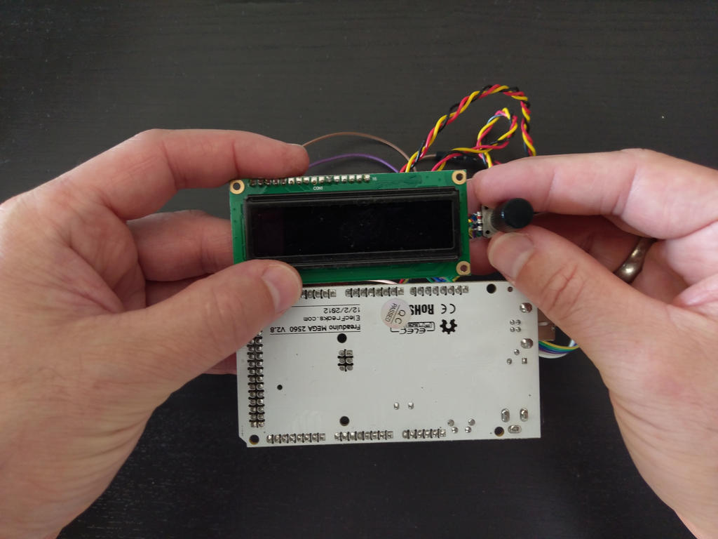
View attachment 14101
A rough idea

Unfortunately these LCDs tend to have a poor viewing angle and a slow response. Both makes for an unpleasant user experience. Therefore compatible OLED display was chosen, which is a true joy to look at and still being affordable. As every idea requires at least a proof of concept before making a decision, that was carried out by connecting everything to an Arduino and writing a prototype software:


An element is selected by turning the knob. Pressing the knob allows to change its value, either directly (if it's a switchable element like an indicator light) or by turning the knob again (like RPM or speed). Should be easy to figure out, even without a manual. After the main components are decided, it's time to arrange them roughly and see about the form factor. The result was in an acceptable range even including the JAE connectors.

As there are two different pin-outs of the gauge cluster (1991-1995 and 1996-2005), as well as different functions depending on build year and options (AT, Tip-Tronic, Targa, ..) carefully preparation of a pin table is essential. Buying the Honda NSX Electrical Trouble Shooting Manual from 1997 and 1992 helped to gather the required information.

Almost all of the 60 pins available at the cluster are in use and realize the following functionality (1997)


  • Temperature, Oil Pressure and Fuel Gauge (resistance controlled)
  • Illumination (PWM controlled)
  • ~30 indicators lights (various controls via battery voltage and ground)
  • Shift Indicator Display (battery voltage controlled logic)
  • Roof Lock Logic (ground controlled logic input and output)
  • Courtesy Light Logic (ground controlling output)
  • Neutral/Park Logic (ground controlling output)
  • Speed gauge (battery voltage rectangle)
  • Tachometer (ground controlled rectangle)

attachment.php
View attachment 14100
1997 AT JDM Cluster

To realize all these in a truly universal fashion would require output drivers that can supply battery voltage, ground at currents up to 2 Ampere, PWM controlled by the microcontroller and even work as input. Such a realization would be possible but quite expensive and certainly colliding with the requirement of a small form factor as well as ease of build-up.

Based on the pin analysis, it turned out that it's sufficient to provide roughly 16 battery voltage and 40 ground drivers with currents up to about 100 mA. These are available as integrated circuits with 8 outputs each, making it just seven components on the PCB. The output pins provided by the cluster were decided not to be considered in this build.

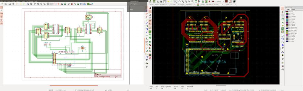
Next is the PCB layout. As two different pin-outs need to be supported, but the output drivers are fixed to either supplying battery voltage or ground, there are going to be two different sets of connection cables. This, on the other hand, allows to optimize the layout as the cable will take care about connecting the correct pins between cluster and tester.
It took a few months to realize this level of complexity (and gave me the chance to learn a lot about the tools involved). The result is the following layout on a 140 x 140 mm PCB with two layers:

attachment.php

Circuit Design and Layout

After printing it 1:1 on paper, the parts (that have to be sourced from at least three different sellers) could be placed to check the correct dimensions before ordering the PCB. Everything worked-out fine at the the order was placed.

attachment.php

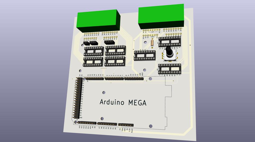
3D simulation of the PCB

While the PCB was being manufactured (which took about two weeks) a crimping tool for the JAE connectors was selected and obtained. Professional equipment found for this task was exceptionally expensive and out of budget for such a project. The Japanese company ENGINEER was found to provide a hand crimp tool that supports the rather exotic 2.0 mm die size: The PA20. It's of decent quality and has served me well so far.
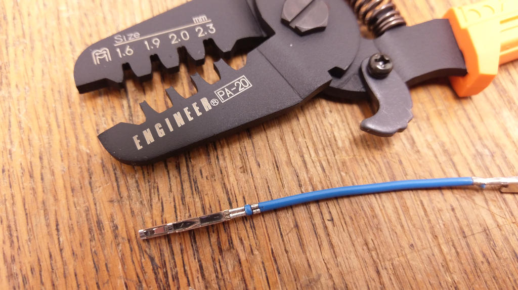
attachment.php

Tool and Result

After the PCB arrived the components were added and soldered. It felt fascinating how exact the parts fitted - the 30 pin JAE connectors, for example, just dropped-in. No comparison to hand-made and drilled PCBs. The display and the rotary encoder worked right away and changing the output of the Arduino's pins could be verified using a multimeter.
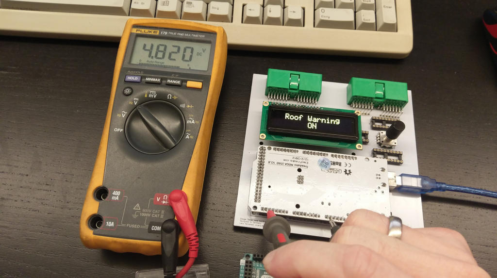
attachment.php

so far, so good

Up to this point, everything went rather smooth but the last 10 % towards the final result are said to be the hardest. After adding the output drivers, getting the cluster from the car and staring to build the connection cable as well as extending the software, several issues came up. These are going to be addressed in the next update to this thread, where each of the clusters functions are going to be show-cased.
Nevertheless, the concept is proven to work and just a few minor changes are going to be required to get it fully running.

During work on the project it became clear that the hardware itself is probably able to drive a range of 1990s gauge clusters from Honda and potentially other vehicles manufactures as well. Unfortunately I don't have any of those to build matching cables and software but it might be a nice collaboration project in case there is interest.


Note
Don't hesitate to let me know you impression of the project as well as ideas on how to improve it further. Especially the software is highly flexible and even making the tester controllable via USB is a possibility (even though I'm not planning to build a super-car simulator yet). Especially interesting are typical use-cases during servicing and/or calibration of the gauge cluster.
 
Last edited:
After initial operation was confirmed, it's time to install the driver chips and attach the individual wires towards the cluster to test the corresponding functionality. Easiest are the indicator lights. Most of them are controlled by providing ground to the corresponding pin. The Arduino pin goes low, so does the output driver and the indicator lights up. Pressing the button enables/disables the indicator light who's name is on the first line of the display.


Three wires can be seen on above video because battery power (ignition) and ground needs to be supplied additionally. Other indicators have a separate power supply or need battery voltage applied to their pin to light up. The user interface is the same but the underlying realization differs.

To handle this in Software, a multi-level architecture was implemented. A top level module called "Display" controls the screen based on information from the module "Element". This reduces complexity as many elements use the same display (e.g. on/off for all indicator lights).

attachment.php


The module "Element" defines different types of elements (e.g. "switch" for on/off ) and creates the connection to the corresponding signal.

attachment.php


The state of each element is retrieved from the module called "Knob". It handles the rotational encoder, and its push-button functionality. Not a trivial task as calculating an element's value from the knob's rotation position requires constant adaptation, e.g. when switching from element selection (top line on the screen) to modifying the element's value (e.g. on/off) and back again. De-bouncing the push-button is required, too. Implementing it in a sensible way is important towards a good user interface as slow reacting buttons or unintended glitches are not a quality indicator.

attachment.php


Each pin and its electrical properties are configured in the module "Signal". It tries to hide most of the electrical properties (e.g. corresponding Arduino pins, inverse logic, etc.) as long as they are not required on element level.

attachment.php


For readers with a less software-centric background this probably not that interesting but it shows that architecture and design doesn't stop at the hardware level. Even such rather trivial software (when done right) is a dedicated, complex and valuable task on its own.

Above diagrams were created using Doxygen. It's a well known Open Source tool to document and analyse source code. Using it helps to create a clean software design and makes the resulting code easier to use.
 
That is a nice development of your original idea. Because I am cheap I would have been inclined to use a couple of male 37 pin D sub connectors on the board and then a female D sub to JAE wiring harness to connect to the dash cluster. Your rotary encoder and board mounted display makes it nice and stand alone. You could add a clip to hold a 9 volt battery to make it completely stand alone; but, I expect that battery life might be rather short once you start powering up the cluster for testing. If Covid 19 leaves you with more free time it might be an interesting development to eliminate the OLED and rotary encoder and do all the control through a serial connection on a connected laptop. Of course this suggestion comes from the guy who doesn't have the skill or patience to go beyond the command line interface:smile:.

Well done!

On a related matter, I am interested in your use of KiCAD. I have the free copy of Eagle on my laptop; but, haven't got to the point of learning to use it. Did you make any comparison of the free design tools when selecting KiCAD? I picked Eagle because it seemed to be the go-to free tool for my Son and his friends when they were taking engineering at university.
 
The D sub connector is an interesting idea. When I compared different options to connect so many wires all of them were more expensive than the JAEs but maybe I didn't search hard enough.
Regarding the 9V battery, this road I won't be trying as the cluster sources more than 3 A at 12 V when everything is powered up :biggrin:

Supplying a command line interface (via USB) should not be that hard as the Arduino supports serial communication natively. The only remaining question is: What would be the use case for such an extension (beside building an NSX race simulator, of course ..) or starting mass production of gauge clusters.

Interesting question regarding KiCAD. I never used anything else in my life (except Mentor Graphics briefly at university, which safely out of everybody's league). So far I've been very happy with it, supporting all I need and being very stable. It doesn't offer things as simulation e.g. but it's sufficient for my needs.
 
The last message was quite software heavy. so now it's back to more traditional electro-mechanics. Let's talk about the three small gauges on the cluster, namely oil pressure, temperature and fuel level. All of them have three things in common: They have the same working principle behind them. The cluster provides a voltage and the sensor has a specific resistance depending on what he's currently measuring.

attachment.php


The combination of the cluster's voltage and the resistance of the sensor creates a current that moves the gauge's needle. But how does the Gauge Cluster Tester simulate a resistance?
That's where the abbreviation "PWM" comes into play. It's short for "Pulse Width Modulation" and provides a nice way out of this dilemma.

For those not familiar with the term, it means that the cluster's voltage towards the sensor is periodically connected to ground instead of through a fixed resistance. As the dial is of low agility it can't follow and settles for a kind of average. This average is roughly the time the signal was connected to ground vs. the time it was not connected.
Not exactly a brand new invention and commonly used in many places where power or current control is required. It's especially popular due to its simplicity and low losses.

The only downside are audible harmonics created at the gauge's coils by the high switching frequency. Sound's little bit like a modern train or tram driving off the station.
Beside this, the control works remarkably well. The Arduino natively supports this type of output and no additional or special output drivers are required.

It's been relatively simple to obtain reference values for the PWM output and store the in the tester. Based on these, a rather simple and intuitive user interface was implemented:

 
The RPM control signal is technically the same as in the first generation tester. A 12 V rectangle signal needs to be created and send to the cluster. Instead of a dedicated transistor circuit the 12 V output drivers are going to be used. Required frequencies are comparably low, therefore no issues were expected.

As often as this sentence is uttered, the result isn't as expected. When trying it for the first time, the needle moved to a maximum of ~4000 RPM and fell back to 0 if a higher value was selected. Sounds like an issue with the signal quality. To further analyse it, my trusted Philips oscilloscope came to the rescue. Its doesn't offer any fancy calculations but it ideal to have a look at the overall wave form.

Looking the the input signal from the Arduino to the output driver, everything looked fine. It's 2 V per division on the display grid making it ~4.6 V peak-to-peak. As the Arduino's logic level is 5 V, that's fine.

attachment.php

Input Signal

The output on the other hand didn't look very much the same. Output voltage is at an OK 12.6 V peak-to-peak but the signal doesn't look very "square". It seems the output driver has issues dropping the voltage back to 0 V after being told to do so. The higher the frequency the bigger the problem until the RPM's detection circuit calls it quits.

attachment.php

insufficient Output Signal


A little research in the data sheet of the output driver showed that it's a so-called Open-Emitter driver and therefore can't actively bring down voltages at its output. As the cluster's detection circuit isn't good at either above waveform is the disappointing result. The good thing: It's easy to solve. Simply adding a 1,5 kΩ resistor between ground and output of the driver. Even if the driver is at 12 V the current at the resistor is very small (8 mA or 100 mW) but helps dramatically dropping the voltage to 0 V:

attachment.php

much better


Integrating this resistor into the tester would be possible without a new PCB design but as it's probably not the last change required, we are going to put on the list of upcoming changes for the next PCB order. For now let's enjoy the quick response of the RPM needle when changing the corresponding value on the tester:

 
This is a great journal of your project, and a great project. I’ve done a few Arduino/derivative projects in Eagle and KiCad. It’s always a learning process, but always super rewarding. I’m quite familiar with the idea of correcting an issue with the PCB, ordering new ones, and then finding the next issue.

I’ve not done the capacitors in my cluster (‘00), so I’m quite interested in this.

In the future, consider the Teensy platform as you can get higher pin counts in a small overall package, with full Arduino compatibility and some often nice additional features.
 
That's great to hear - I've learned a lot on the way, especially related to HW.
A delivey for a specific MOS-FET is currently on the way. When the prototype works as expected, the new PCB can be designed and ordered. It would be nice if it would spread beyond being a pet project of mine.

The Teensy sounds interesting, as of now I'm only using a specific timer library from that area but I'm going to have a look.
 
The gauge cluster used in all previous videos and pictures is from a 1997 AT NSX with manual shift control at the steering wheel. Due to this, the RPM dial contains an extended shift indicator. The '3' location has been renamed to 'M' and enables a small display on the side that shows the currently selected gear.

attachment.php

1997 AT (JDM)


Without any bus communication and considering the electrical backwards compatibility with existing switches and ECUs, this results in an overall number of 10 pins used to control the gear indicators on the dash.
Having individual elements to control them would be highly confusing, especially since some of the indicator lights work by connecting to ground other to battery voltage (depending on the indicator) and the three pins for the gear number display are of a rather uncommon standard used in older tabulator machines.

The issue can be nicely solved in software, though. As mentioned in a previous message, the signal module takes care of basic pin behaviour (like connecting to ground or to battery voltage) the element module one layer above groups signals into elements to be displayed and changed by the display module. Configuring the signals properly and introducing a new gear selection element with corresponding graphics resulted in a user interface that simply scrolls through all possible options:


Note that some of the indicators react a little slow - this is due the output pins of the Arduino not being put into the correct mode causing the output drivers not to be triggered sufficiently. It's already fixed and the indicators are now lighting up fast and crisp - just like they should.
 
Last edited:
One big dial is still missing, the speedometer. The exact design of the corresponding signal can be found in this forum entry.

Utilizing the new hardware, a separate driving circuit is no longer necessary. One of the output drivers that provide ground can be used to simulate the VSS (Vehicle Speed Sensor). It was a little surprise to me that everything worked right away:


Testing the speedometer should not take too much time as the odo and trip meter starts running, too. All bench testing combined already put about 20 km on the car without moving it an inch ..
wink.png


The number of cables running towards the gauge cluster in above video increased significantly. A nice example why bus communication became, at some point, necessary for modern cars.

All main functions are all running now but three minor issues have been detected and need to be corrected in a new PCB design. We'll talk about those in the next days.
 
Thanks, for all the positive input.
Currently I'm still waiting for another delivery of MOS-FET transistors to be able to resolve one of the issues with the realization.
Overall very happy so far.
 
Fantastic work! Having done a few similar projects, I know how much time and attention to detail this takes. It's also super helpful to the (many) other owners that will need to do this in the future.

I've been meaning to replace the caps in mine for a while. While I'd be happy to do the calibration myself I'm a bit short on time, so I'd be interested if you offered one of the following options (in order of preference):

1. A North American calibration service. [MENTION=26435]Old Guy[/MENTION], is that something you'd be interested in doing? Otherwise I think shipping would be prohibitively expensive.
2. An assembled PCB kit with harness for a specified year \ configuration
3. An unassembled kit with harness for a specified year \ configuration. This could also be a digi-key cart, gerber files, and pre-crimped wires. I don't mind crimping, but buying the tool to use it once is inefficient. Maybe we could compare the cost of shipping cables versus buying the tool. Obviously all of this information would cost something - maybe you could sell a "design package" or something like that.

Will you be sharing the KiCad files? I ask because I've got a separate project using a 90s legend cluster, and I've never quite been able to get the fuel \ temperature gages to work quite right.

My $0.02 on the PCB design - great work, first off. I know how daunting it can be to get into that. A couple of observations:
- The board houses I've used charge by the area for boards - you could potentially save some money by stacking the board on top of the Ardunio and placing components in between all of the pins. For these sizes it's not that big of a deal, just an observation
- What I've done in past projects is to buy a 12V laptop-style power supply, then just put the matching barrel jack on the PCB. That way you've got a high-current 12V source for powering the gague cluster without having to use additonal ICs (if I understand what you've done correctly)
 
Thanks for the positive feedback and sorry for the late reply - had a terrible headache this afternoon and won't be doing much this evening.
On the positive side, the long overdue MOS-FET delivery arrived yesterday. The part has already been incorporated into the circuit and PCB design but needs a prototypical test run before finalizing the 2nd revision PCB and ordering it.

  1. Shipping between Europe and the USA is terrible, currently. Even small items are very expensive so you're right that shipping a cluster is over the top.
  2. Target for the Mk2 tester is to develop a tool that's fast and easy to use, as well as simple to assemble. Matching that, the plan is to provide a complete tester, plug-and-play, so to speak. Using different cables it is able to drive different build years and versions of clusters.
  3. A kit would be an option but trying to keep things simple for now*
    PS: Just in case, crimping is the most time consuming element of assembly so in a kit that would most likely become a task for the DIY-ler, even if it means to ship the crimping tool together with the kit :biggrin:

*Due to the high supply voltage a special Arduino type is required which can be difficult to source. Flashing the Arduino without the source code (which depends on a specific development environment as this is more code than a regular Arduino sketch) isn't exactly easy, too.

The power supply of the tester is realized the way you suggested. The ICs are required to be able to switch voltages different from the 5V logic of the Arduino and because they are compact and sufficiently powerful.

Now to the open points ahead:
  1. New PCB layout to be tested, verified and ordered.
  2. Only the 1997 AT JDM non-targa cable/pinning is completed. @drew is going to help checking against other build years, especially the most common <1995 version.
    The new PCB will require some small pinning changes, too.
  3. Assembled cables need to be tested for correct pinning without a cluster at hand (the cluster needs to go back into my car ..)
  4. Software changes and improvements need to be checked against a working cluster (recently bought an old Legend cluster for that).
To be able to provide a tester, the first two points above need to be completed but I'll keep everyone updated.

If you're in a hurry, the first version of the tester is tested and released as open source including parts lists, etc. It probably won't be easy to realize as it includes a specific Arduino type which requires a replacement as it's currently unavailable (there is a suitable one available in the US) but in case you want to walk that path let me know and I'm gonna help you along the way. Not everything needs to be exactly identical (e.g. the housing) so there is some wiggle room available.
 
Last edited:
1. A North American calibration service. @Old Guy, is that something you'd be interested in doing? Otherwise I think shipping would be prohibitively expensive.

I used to have a numbered company for doing consulting services. That is long ago history and I now lead a life of leisure / laziness. I suggest that it might be a better option to see if Brian K. (NSX E Repair) is prepared to consider providing a capacitor replacement and calibration service as that is sort of his bread and butter.

If Brian K. does not want to get into it, and all you need to do is calibrate the speedo and tach, Heineken's first version software and an Arduino Uno should do nicely (or his complete version 1 tester which requires a Freeduino like version of the Arduino Uno). At one time [MENTION=18194]Honcho[/MENTION] was talking about acquiring version 1 of Heineken's tester. If he has, perhaps he would be willing to do the 'sell it on' thing once he is done with his calibration. Once the cluster for the Type S project is calibrated, its not like he will need it for another 20 years or so..
 
This is the final update to complete the circuit and PCB design. Two issues have been observed while prototyping the tester:

  • The output drivers are too weak to supply the gauge cluster illumination (driver chip overheats)
  • The output drivers internal voltage drop is too high for the fuel gauge (doesn't reach maximum)
  • Not enough ground pins
There has been some delay as the parts required to solve above issues where stuck in transit for almost two weeks, sorry for that.
Let's have a more detailed look at the problems and their solution.

Weak Output Drivers
The cluster's minimum current usage is ~1 A (at 12 V). Enabling all warning lamps pushes it over 3 A, adding illumination results in more than 4 A. Summing that up we are looking at ~50 W being used by the cluster (with illumination switched on). As most of that current is distributed across a large number of pins it's not a problem for the tester but illumination draws ~1 A across two pins with the left connector being responsible for 2/3rd or 0.75 A.
Each driver output pin can provide ~0.1 A. Enough for most of the cluster but not for those 0.75 and 0.25 A illumination pins.

Driver chips with similar characteristics but higher output rating aren't available so it becomes necessary to add more punch to the affected illumination pins by means of a discrete circuit. Out of curiosity, the decision was made to realize it with MOSFET transistors. Those are more and more common today as they typically have very low resistance, fast switching and are often controlled digitally with high frequencies.
Only the first of those main advantages serves as a bonus in this application but the others won't hurt either.


attachment.php

The circuit ..


attachment.php

.. the wire connected MOSFET ..


attachment.php

.. and the result


The internal resistance of the MOSTFET is so low (0.05 Ω in case of the IRF5305 used here) that it could handle up to 30 A and therefore didn't even get warm during testing. Note that another pull-down resistor is required to avoid the problems observed during RPM gauge control. Case closed, on to the next change.


Too high internal Voltage Drop
Driving the fuel gauge is done by periodically pulling down the reference voltage from the cluster to ground (PWM control). If it's permanently pulled to ground the gauge exceeds the "full" level. Unfortunately, the output drivers have a minimum voltage drop associated with them that prevents a complete pull to ground. The needle stops a few milimeters before hitting "F" so that gauge is not fully testable.

As mentioned above, MOSFETs feature a very low internal resistance (and a corresponding low voltage drop) so using one of them instead of the driver IC should solve the issue. As the order of the was delayed by several weeks it took a while until the circuit could be tested.


attachment.php

The circuit ..


attachment.php

.. more extra wires ..


attachment.php

.. and it works


The selected IRLD014PBF can be directly controlled by the Arduino and provides an internal resistance of 0.2 Ω. As the fuel gauge is specified to display "F" at 3 Ω, that is indeed low enough as it can be seen above.

Final location of the two MOSFETs and the one pull-down resistor was decided to be between the two green connector sockets. The 3D view of the PCB editor provides a nice preview of them on the final PCB:


attachment.php


Not enough Ground Pins

After one more careful review, new PCBs are going to be ordered. These will include a few more improvements (especially related to layout and pin numbering) and an additional ground pin. Most of the changes can be covered in software but one or two wires need to switch positions on the connector to make everything work.

Remaining Steps
Several items remain on the To-Do-List before the project can be considered done. One of them is to be able to return my cluster to the car which means the connection cable to the cluster needs to be documented and a PCB created that allows to check copies of that cable without connecting it to a real life cluster.
One more important step is to provide a cable supporting the <1995 clusters. As no such cluster is available to me, [MENTION=5430]drew[/MENTION] is gonna help with that.
To be able to continue working on the software without risking to break functionality an old Legend cluster (374,000 km) was acquired and needs a matching cable set, too
A significant amount of work but very much looking forward to it
smile.png
 
Last edited:
Great work! This is a huge service to the NSX community, your documentation is certainly appreciated.

Since you mentioned a legend gauge cluster... here is the project I worked on in the past. I can't believe it was 6 years ago! I've learned a LOT since then, so don't judge me too hard - I certainly did a few things the hard way. After that post I designed up a PCB to drive the cluster, but I was never able to get the temp \ fuel gages to work. I tried to get clever and PWM the signal pin using two parallel resistors, one with a FET in series - when the FET was off the resistance was the "high" resistance value from the service manual, and when it was on it put the two resistors in parallel, making the Req the "low" value on from the service manual. Long story short - it didn't work. I'm going to take what you've learned and fix my project (at some point).

If you need the documentation I've got, I'd be happy to send it your way.
 
Last edited:
Thanks crxguy52, that's a cool project of yours!

The FET setup sounds a bit complicated but it should work, assuming the cluster is properly powered (which it seems to be as the speed gauge won't work otherwise).
An interesting read, as it shows that there are a lot ways to reach the same target. And even if it could have been done simpler, there's a lot to learn on the journey.

PS: I paid nearly 50 Euro for my legend cluster, it came in terrible condition and with 375,000 km :biggrin:

PPS: After a second review, the new PCBs have been ordered yesterday.
 
Last edited:
Long time without an update but since work, home schooling and home kindergardening started again, time for hobbies became limited.

The ordered PCBs arrived end of January. Valuable parts were remove from the previous board (like the JAE AG5 connectors and CMOS ICs) and moved to the new board.
It took about 1.5 hours to fully assemble it (excluding the connection cable) which, in my opinion, is a respectable speed-up compared to the old version

attachment.php

soldering done


attachment.php

parts attached


attachment.php

a quick test run


The new PCB features features almost 200 additional labels, identifying Arduino pins, starting at the microcontroller's output, across the output driver ICs and up to the cluster connectors. This will help to diagnose any issues while developing new cable looms or if something should behave strangely.

As the pinning and internal signal routing was optimized, software changes had to be made as well as a hand full of pins changed at the connector. When this work reached the cluster's illumination, strange things happened: The backlight was permanently on, couldn't be switched off and the MOS-FET transistor became fairly warm - turned out I had misread the circuit diagram and created a PCB with inverse MOS-FET pins. Nothing that can't be fixed with two cuts and repair wires but a little disappointing nevertheless. It's been fixed in the circuit design and is going to be reflected in the next order (the diagram in above post has been corrected, too).

As I'm cooperating with @drew a second tester was assembled and with experience from the first round, it took only about an hour. To visually spice things up a little, a white OLED display was chosen - the price is nearly the same, otherwise pin and software compatible.


attachment.php

a second copy


attachment.php

a full featured christmas tree


Besides the tester, a working setup needs matching cable loom, too. With a bit of experience, the crimping and assembly takes a little more than an hour of slightly brain numbing work. Much less than the soldering and shrink-tube intensive work for the previous generation tester. All that's needed in addition is a 12 V barrel connector power supply with 5 Ampere.

attachment.php

wires cut to length


attachment.php

stripped wire ends


attachment.php

~60 pins crimped


For the >1995 clusters I would consider the work done. Remaining tasks are documentation (BOM, etc.) and the <1995 loom, of course. As of today, the software and loom is tested to support 100 % of the display functions on a JDM 1997 AT non-Targa NSX cluster. Looking at the available pinning information that should cover more than 90 % of the functions on all >1995 NSX clusters. Support for <1995 clusters is being created with the help of drew.

Nevertheless, there are still combinations that are not tested yet (e.g. targa warning light, immobilizer indicator, etc.) and I'm looking for European members that would like to support - maybe combined with a capacitor replacement and calibration. Please contact me if you're interested. If you're from anywhere in the world and looking for a tester and loom of your own, you're welcome as well :smile:

PS: With the right software and loom, the tester should be able to drive many Honda and other clusters from a similar age. A 1994 AT Honda Legend cluster will be the next candidate on the list as it should allow me to put my cluster back into the car but to still have equipment available for tests.
 
Last edited:
Back
Top