• Protip: Profile posts are public! Use Conversations to message other members privately. Everyone can see the content of a profile post.

Uncoupling headlight-on and interior-dim

goldNSX said:
On page 1038 of the service manual there is a 'Daytime running light control unit (IG2)' where there must be a fuse in the dash fuse box No. 3 (7.5A). Anyone tried to remove this fuse?
That goes to the CA Spec daylight running light module - see page 1158
This fuse is not installed on a US Spec car.
It just supplies power when ignition switch is 'on'
 
I DID IT! :)

I nearly drove me nuts but the releave now is a big pleasure.
Thanks to Jesus it all worked in the opposite direction I thought it will work, just some few hours of Murphy's law. :)
It didn't work with the wiring D'Ecosse showed above cause the light signal interact with each other meaning the stereo behaves different if the clock is plugged. The AC works really crazy. So I decided to use THREE switches, one for each task. Looks like an airplane in my cockpit now. :) But this is easy to solve via 3 relais. The AC is very confusing. There is a red/black wire that acts digital for showing light ON/OFF, no problem with that, BUT the dimming light which is used for the background light of the AC INTERACTS with the red/black wire. If you unplug the dimming wire the letters are dimmed (THE OPPOSITE!). If you unplug the red/black wire the letters get bright but as soon as the light is switched on the letters start to oscilate the darker the instruments dimmer is regulated. :confused: The dimming wire on the AC gets 0.5 Volt to stabilize the letter oszilation and gets to about 7.5 Volt with the instruments completly dimmed. I started to experiment with resistors BUT failed. It's ok for me because the AC letters are only oscilating with the light on and the instrument dimming not at max. I don't have a problem with that during the day and during the night I use the switch and do also get no oscilation. But perhaps someone finds an solution to that.

But the great news is that I can read the middle console during a sunny day and the headlights on (as it is usual here in Switzerland)! :D the harder the work is the higher is the pleasure! :D

But I have to say: it's not a straitaway DIY.
 
goldNSX said:
....It didn't work with the wiring D'Ecosse showed above cause the light signal interact with each other meaning the stereo behaves different if the clock is plugged. ....
Sorry - that doesn't make any sense Thomas - I definitely mis-identified the correct input for the dimming on the A/C (the digital not the variable analog) and should have had the red/black not the red but all three of those come from the same source i.e. 12V when the light switch is on. There is no isolation between any of these three signal electrically so there should be no requirement to isolate them with individual switches.
Now you certainly can't combine the variable (analog) dimmer for the A/C (on the red wire input) with the others, but the other part for the three digital inputs doesn't hold up from a technical analysis.

See the attached extracts from the schematics - note that all three of those inputs to the digital dimming functions originate from the same fuse & are all electrically at the same point
 

Attachments

  • dimmer.JPG
    dimmer.JPG
    36.7 KB · Views: 202
  • clock_dimmer.JPG
    clock_dimmer.JPG
    13.2 KB · Views: 184
  • AC_light _dim.JPG
    AC_light _dim.JPG
    37 KB · Views: 188
  • radio_dimmer.JPG
    radio_dimmer.JPG
    19.1 KB · Views: 180
Last edited:
I doesn't make sense to me either. :) I just had these phenomena during the install and testing. I took the red/black on the AC from the beginning. But besides that: how can the stereo work different if the clock is plugged/unplugged. I have no answer to this till now. :confused: I always believed that they come from the same source but the result was different. :confused:
Ken, did you do this mod too and did it work the way you showed it in the diagram?
 
goldNSX said:
.... But besides that: how can the stereo work different if the clock is plugged/unplugged. I have no answer to this till now. :confused:
That makes no sense either Thomas - there are no outputs from the clock that can affect this - there is a constant supply via the clock fuse from battery, an ignition fed supply, the light dimming signal & ground. It's impossible for the clock to have any affect on that signal.

.... Ken, did you do this mod too and did it work the way you showed it in the diagram?
No - I don't even have 2 of the three components! Only one left for me is the AC module. So I haven't tested my 'theory' empirically but am confident of my interpretation of the schematics.
 
D'Ecosse said:
So I haven't tested my 'theory' empirically but am confident of my interpretation of the schematics.

I would have come to the same conclusion like you, Ken. It doesn't make sense to me either. :) I'll send you a video of the AC module light oscilating as soon as I have the camera in the car. It's very strange.
But thank you for your input! :)
 
ok i tried this mod today.

since i've installed HIDs, i drive with them on during the daytime now. it's safer because other drivers can see shimmering lights.
but what i couldn't stand is not being able to see my clock/ac/radio display during the day.

what i did was, yanked out the red&black wire from each module.
the displays are definetly always in their bright mode now with my headlights on.

but driving at night i noticed the ac knobs and radio knobs&buttons no longer lit up at all. DOH!

any help?
 
but driving at night i noticed the ac knobs and radio knobs&buttons no longer lit up at all. DOH!

any help?

Now that you changed the dimmer circuit that feeds the clock, climate control, and the radio to cause them to light brighter, you have to go into the internals of each of those units to do some kind of a hack job to light the bulbs.
 
I just finished doing this mod. I really love this. Nice and bright during the day driving with the park lamps on. Flip the switch and they go back to stock dim at night. GREAT!

Thanks to D'Eccosse for the information on this. We lost a good man when he sold his car and left.

The biggest problem I had doing this was finding my glasses which were lost for 30 minutes hanging in the front of my shirt!
homer_simpson_doh_02.gif
 
Interesting how this evolved.


In Canada we would have installed a Day-time-running light module.

High Beam Head lamps on at half brightness.
You would have the same control of your dash lamps and your DTL are on when ever the engine is running. Tail Lamps and markers are not on.
After maket DTL modules are sold at auto stores.

I do like what you did though.
 
Now that I'm nearly retired, and after 8 years of being frustrated by the interior-dim problem, I decided to make D'Ecosse's 3/18/2006 circuit (the more complex one) work in my car. It is a 100% success after a few minor, but very important, changes. The switching is very clean - no flicker when going under bridges, etc. (So as a retired electrical engineer, I haven't lost all my design skills yet. :biggrin:)

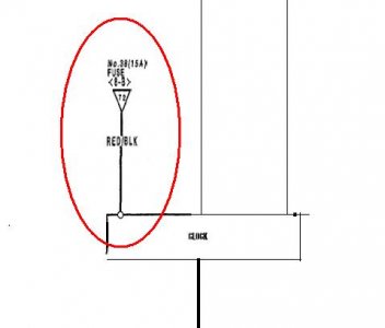
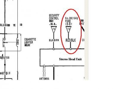
I built the module so that the cable that went to the clock goes into the module. The module then has an output cable that goes to the clock. One new lead from the RED/BLK leads at the connectors to the ACCU and radio plug into the module. And there is an input connector from the LDR.

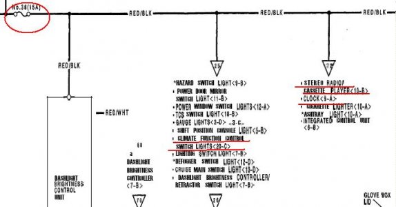
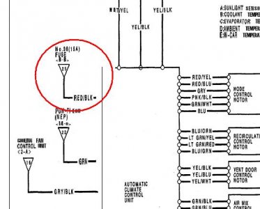
As noted in his updates, the output goes to the RED/BLK lead on the ACCU (AC control unit), not to the red lead. In addition, I added a 1 Kohm resistor from the NC contact of the relay to ground. This guarantees a ground on the controlled red/blk lead when lights are off or it is bright outside. (Other dash lights, etc provide that function when all the leads are connected together. With this control circuit added, it is possible for the clock to leak enough current into that lead so that the radio lights come on even with the car off. The 1K ohm resistor bleads off the leakage current).

And finally - the key modifcation that caused others fits: You need to insert a diode in series with the RED lead on the ACCU. I actually did this inside the ACCU. No board modifications were needed; there was a convenient wire to cut and insert the diode.

One remaining problem to solve :redface:: finding a path underneath the dash board to install the LDR (light sensor) in the front of the dash near the light sensor used by the ACCU. So, for the moment the lead to the LDR comes out of the console at the top of the clock and is lying on the dash.

QUESTIONS:
1. Is anyone interested in my final schematics and seeing my installation pictures?

2. Does anyone know a good sneak path for the LDR to get to the clock connector area from around the defroster vents & ACCU photo-sensor at the very front of the dash?

Frank
'96 NSX0-T, red/tan

PS: My '84 Corvette came equipped from the factory with this type of automated control on the readouts, so it was obvious there was a reliable solution for the NSX. I just didn't have the time before to dig into this. It took days to measure the characterisitcs of the clock, radio, and ACCU, try various alternatives, then come up with the two simple but not so obvious mods. Building & installing the circuit was the easy part.

I first attempted to use the factory photo-sensor for controlling the ACCU, which detects high levels of sunlight and adjusts the AC fan speed etc in anticipation. However, that sensor had too little change in output voltage at the light levels where the dim/no-dim decision needs to be made. I amplified and level shifted the signal, but the voltage variations were still too small to reliably detect over full temperature range. So, it was back to using a separate LDR
 
So what's the final story for the CCU?
Clock seems to be easy.

What wires are we cutting on the CCU to get rid of the light dimming during the day?
1 red/black? 2 wires?
 
What would be really cool is to have the lights stay bright if the gauge cluster dimmer control to the left of the steering wheel was set to max brightness. Anything less than max bright on that knob, and they would revert dim mode.
 
That goes to the CA Spec daylight running light module - see page 1158
This fuse is not installed on a US Spec car.
It just supplies power when ignition switch is 'on'

D'Ecosse -

On the off chance that you still post and see this...would you mind educating me a little further on a related topic?

I see above you reference a page 1158...I have the Acura Service Manual for a 1991 and I see in section 23-12, 32/33 that the module exists and where the wiring harness runs. What I would love to understand, is which fuse you reference that is missing on US spec cars (i.e where can it be found?)

Backstory is that I found a set of DRL and would love to install them, assuming I can insert a fuse and my DRL module is in fact within the car. Two large assumptions, but I hope I am lucky to have them.

Many thanks in advance.
 
What would be really cool is to have the lights stay bright if the gauge cluster dimmer control to the left of the steering wheel was set to max brightness. Anything less than max bright on that knob, and they would revert dim mode.
I developed the following modification to the stock Stereo and Clock circuits to override the dimming function when the dash brightness knob is turned to max brightness. When the knob is adjusted lower, the Stereo and Clock will dim normally. This all works “behind the scenes”. There are no new switches or light sensors to activate while driving, other than the factory adjustment knob. My total material cost was $12 plus a few jumper wires and crimp connectors.

The key to this modification is a digital voltmeter with programmable relay output. See link below, I purchased it online through ebay. The “EAZY-IV-U3” voltmeter will monitor the adjustment knob’s output voltage. When the knob is increased to above a preset level, the relay will switch state, disabling the dimming function of the Stereo and Clock. In order to monitor the knob output voltage, its harness just gets a “T-tap” added to the Red/Green signal wire. The digital voltmeter can be placed in any location desired.

The stock Stereo and Clock harnesses will need to be modified (cut) per schematic below. The car side of the stereo harness (pin 3) Red/Black wire will become the power supply for the voltmeter. A jumper wire ties the NC (normally closed) relay output to this power supply.

The Stereo side of the harness (pin 3) Red/Black wire will be connected to the relay “common” terminal. This enables “normal” dimming operation when the adjustment knob output voltage is below a preset value. The Red/Black wire from the Clock can then be cut and connected to this signal wire, if Clock dimming override is also desired. I did not take the extra step to cut the Red/Black wire in the A/C harness, but I believe that it could have been controlled in the same way if I wanted to.

Connect the car’s ground to the relay GND screw at any convenient point, I used one of the lower Stereo mounting screws. When the relay was activated to override dimming in both the Stereo and the Clock for the first time, I saw the same strange behavior as described in the 6/30/06 goldNSX post… the Clock was actually leaking enough voltage onto the Red/Black wire to activate the dimming function of the Stereo. So, I jumpered the relay output NO (normally open) contact to the GND screw, and the problem resolved.

Programming of the unit is performed with the aid of the operating manual (click link below). In programming mode “P-1” there is the capability to add a relay on delay timer, relay off delay timer, and to turn off the unit’s LED display after startup. I left these parameters at “000”, “000”, & “d-0” which means no delays, and the LED display remains on indefinitely. If everything was hooked up correctly the voltage should now be displayed on the LED display, and will change value as the dash brightness adjustment knob is rotated. Note the number of Volts observed on the LED display when the dash brightness adjustment knob is turned all the way up (Up is to the left, which has always seemed backwards, but I digress). On my car, the max Voltage was 2.4 Volts. Hold down the “ENTER” key for 3 seconds and use the “SET” key to select programming mode “P-2”. Set the Upper and Lower limits to just below the maximum Voltage level, or 02.3 Volts in my case. Make sure the remaining parameters are set to their defaults of 0.0, dL0, and “ON H”.

That’s it, now just put everything back together! See Youtube video for a quick demo of the voltmeter relay in operation:
https://www.youtube.com/watch?v=V-AjeEwjr6k

References:
https://www.bimblesolar.com/docs/digital-relay-E1200.pdf
https://www.ebay.com/itm/12V-24V-Di...-Timer-Time-Delay-Switch-Module-/181635863945
http://nsxe-repair.com/CCUremoval.html

Schematic.JPGDash Removal.JPG Adjustment Knob Harness.jpg Stereo Harness.jpg Clock Harness.jpg Voltmeter2.jpg
 
Last edited:
I developed the following modification to the stock Stereo and Clock circuits to override the dimming function when the dash brightness knob is turned to max brightness. When the knob is adjusted lower, the Stereo and Clock will dim normally. This all works “behind the scenes”. There are no new switches or light sensors to activate while driving, other than the factory adjustment knob. My total material cost was $12 plus a few jumper wires and crimp connectors.

VERY cool! If/when my stereo needs to be refurbished, I'll probably take a stab at this as well. Thank you for the detailed write up!
 
Back
Top