MATERIALS
SQ TUBING HOT ROLLED 1 ½” x 1 ½” x 1/8” wall steel:
(1) - 31” long(rear cross tube)
(1) – 35 ¾” long with both ends cut at 45 degrees ^--------^(front cross tube)
1) – 19 1/4” long–trim to length(front to back connector tube)
(1) – 18 1/2” long-trim to length(front to back connector tube)
(2) – 2 ½” long(rear cross bar uprights)
(2) – 7 ½” long with one end cut at 45 degrees(front cross bar uprights)
(1) – 25” long-trim to length(under pan/tranny cross member)
FLAT BAR 2” X 3/8” HOT ROLLED steel:
(4) – 3 3/8” long
(2) – 4” x 5” by 3/16”
(4) – 4” CASTERS WITH BRAKES – Tractor Supply
(2) – ½” ID x 1” long spacers for front attachments
(2) – 10mm x 25mm or so bolts for rear attachments
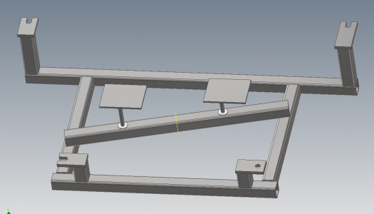
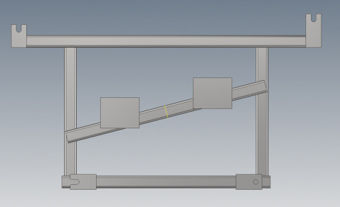
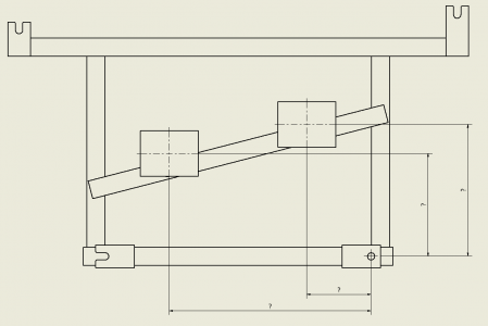
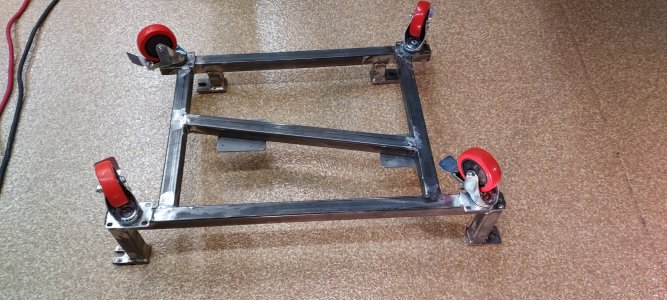
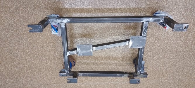
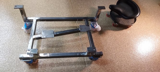
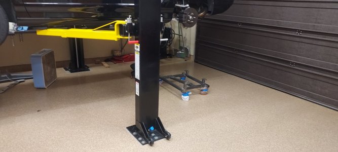
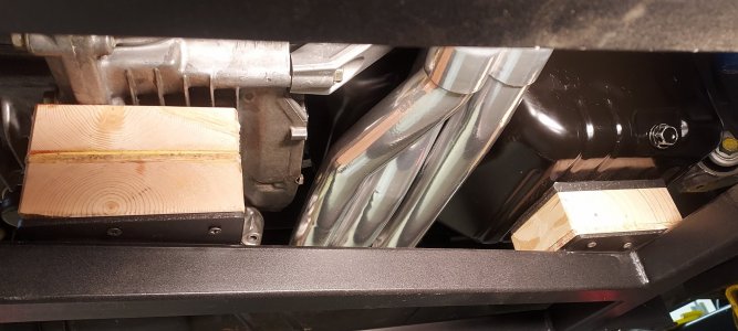
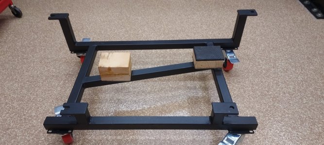
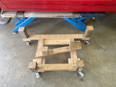
I really like the wood cradle done by prime member BUTTERS(pic attached). As an old metal banger i chose to make a steel model. So if you have decent welding skills here is a blow by blow. An aluminum cradle would be really cool to match this car, but that would be indulging my OCD to crazy time. The attachment points for this cradle are a rhombus and not on the same plane making this difficult to measure up and make totally on the bench. Even with CAD dwg’s, chances of getting a fab shop to make their first one to fit is iffy. Since my is already up in the air and my center beam is out, I chose the quick and simpler route. I bench fabbed the front and rear crossmember U shaped uprights by themselves on the bench. The front U member dimension from inside upright to inside upright is 32 ¾” and 37 ¾” from hole to hole. The rear U member dimension is 17 15/16” inside upright to inside upright and 22 15/16” hole to hole. All holes 5/8” or slots on one side for ease of installation(i highly recommend the slots). Then loosely bolt these two U members to the sub frame and then measure between them, trim the two front to back connector sections and tack weld them into place under the car. The sideways location of these connectors is not important but mine are 23” inside to inside. Then fit the angle tube lined up under the oil pan and tranny and tack. Then remove the tacked up frame and finish it on the bench(driveway in my case–welding splater/grinding debris on that soft Berlina Black paint –NO!). I ordered all the parts cut to size (except for the three ordered long for house trim) from a local decorative metal weld/fab shop(Fortin Welding Columbus ohio)for just $123. I used 6013 rod, 3/32”/AC 70 amps for tacks and 1/8”/AC 106 amps for all else. If your welding skills are iffy, go to 3/16” wall tubing as you will be less likely to burn thru, but this type of weldment does not need great welds. To finish off I then welded the 4” by 5” plates on top of the under engine/trans diagonal bar. I then built up a 2 1/4” wood/rubber pad under the pan and a 3 1/4” all wood under the tranny. Total outlay $180. My 92 has some leaky valve covers, cam seals and i just purchased a 3.2 from a wreck, so this cradle will see use soon. Did my own tranny gears and R diff decades ago, but just now in 31 years need to pull the mill. REVISION FOR JACK STAND USE: I designed this for a MaxJax which is a 42” lift(45-46” clearance) lift. But here are revisions for max “slam” for use with a lower lift height. A cradle can go maximum 2” lower than the design above. Make the front risers 2” shorter, 5 ½” instead of 7 ½”. The rear cross member will have to be moved toward the front by 2 ½” shortening the front to rear “connector” tubes 2 ½”. The rear risers are totally eliminated. The original design has the rear flat bar tabs going sideways, now rotate them so they go to the rear and line up with the rearmost 10mm threaded holes on the subframe. The tabs are now welded directly on top of the rear cross member. A loose ½” spacer will now be needed above the rear tabs. The oil pan plate will only need a ¼” thick piece of rubber, the tranny pad around 2” wood. The tractor supply casters are really nice but 5”overall height. Another inch or more can be gained with a lower caster. GRAINGERS.COM has a lower one without a brake. Happy to do clarifications. Was an active member of the original big list(under autoLL), but been away for over a decade and glad to contribute to this great community.
SQ TUBING HOT ROLLED 1 ½” x 1 ½” x 1/8” wall steel:
(1) - 31” long(rear cross tube)
(1) – 35 ¾” long with both ends cut at 45 degrees ^--------^(front cross tube)
1) – 19 1/4” long–trim to length(front to back connector tube)
(1) – 18 1/2” long-trim to length(front to back connector tube)
(2) – 2 ½” long(rear cross bar uprights)
(2) – 7 ½” long with one end cut at 45 degrees(front cross bar uprights)
(1) – 25” long-trim to length(under pan/tranny cross member)
FLAT BAR 2” X 3/8” HOT ROLLED steel:
(4) – 3 3/8” long
(2) – 4” x 5” by 3/16”
(4) – 4” CASTERS WITH BRAKES – Tractor Supply
(2) – ½” ID x 1” long spacers for front attachments
(2) – 10mm x 25mm or so bolts for rear attachments
I really like the wood cradle done by prime member BUTTERS(pic attached). As an old metal banger i chose to make a steel model. So if you have decent welding skills here is a blow by blow. An aluminum cradle would be really cool to match this car, but that would be indulging my OCD to crazy time. The attachment points for this cradle are a rhombus and not on the same plane making this difficult to measure up and make totally on the bench. Even with CAD dwg’s, chances of getting a fab shop to make their first one to fit is iffy. Since my is already up in the air and my center beam is out, I chose the quick and simpler route. I bench fabbed the front and rear crossmember U shaped uprights by themselves on the bench. The front U member dimension from inside upright to inside upright is 32 ¾” and 37 ¾” from hole to hole. The rear U member dimension is 17 15/16” inside upright to inside upright and 22 15/16” hole to hole. All holes 5/8” or slots on one side for ease of installation(i highly recommend the slots). Then loosely bolt these two U members to the sub frame and then measure between them, trim the two front to back connector sections and tack weld them into place under the car. The sideways location of these connectors is not important but mine are 23” inside to inside. Then fit the angle tube lined up under the oil pan and tranny and tack. Then remove the tacked up frame and finish it on the bench(driveway in my case–welding splater/grinding debris on that soft Berlina Black paint –NO!). I ordered all the parts cut to size (except for the three ordered long for house trim) from a local decorative metal weld/fab shop(Fortin Welding Columbus ohio)for just $123. I used 6013 rod, 3/32”/AC 70 amps for tacks and 1/8”/AC 106 amps for all else. If your welding skills are iffy, go to 3/16” wall tubing as you will be less likely to burn thru, but this type of weldment does not need great welds. To finish off I then welded the 4” by 5” plates on top of the under engine/trans diagonal bar. I then built up a 2 1/4” wood/rubber pad under the pan and a 3 1/4” all wood under the tranny. Total outlay $180. My 92 has some leaky valve covers, cam seals and i just purchased a 3.2 from a wreck, so this cradle will see use soon. Did my own tranny gears and R diff decades ago, but just now in 31 years need to pull the mill. REVISION FOR JACK STAND USE: I designed this for a MaxJax which is a 42” lift(45-46” clearance) lift. But here are revisions for max “slam” for use with a lower lift height. A cradle can go maximum 2” lower than the design above. Make the front risers 2” shorter, 5 ½” instead of 7 ½”. The rear cross member will have to be moved toward the front by 2 ½” shortening the front to rear “connector” tubes 2 ½”. The rear risers are totally eliminated. The original design has the rear flat bar tabs going sideways, now rotate them so they go to the rear and line up with the rearmost 10mm threaded holes on the subframe. The tabs are now welded directly on top of the rear cross member. A loose ½” spacer will now be needed above the rear tabs. The oil pan plate will only need a ¼” thick piece of rubber, the tranny pad around 2” wood. The tractor supply casters are really nice but 5”overall height. Another inch or more can be gained with a lower caster. GRAINGERS.COM has a lower one without a brake. Happy to do clarifications. Was an active member of the original big list(under autoLL), but been away for over a decade and glad to contribute to this great community.

")