• Protip: Profile posts are public! Use Conversations to message other members privately. Everyone can see the content of a profile post.

Big McLargeHuge’s 1990 JDM NSX Adventure Thread

Thanks guys :smile:. Slowly but surely I'll get everything working & looking good again.


Just FYI, the diff from your auto should fit the 5-speed. IIRC, they are identical.

Good point, I had briefly thought about that but dismissed it since I thought the parts were different. Looking again, it's only the ring gear that has a different part #, the other diff parts look to be shared which wouldn't be an issue since I'd be replacing the ring gear anyways.

Could be interesting. My plan was never to open the auto trans once removed, it looks like opening it requires a housing removal tool & new gasket but maybe not too bad. I think the main issue is the chronology, I wanted to have the rebuilt M/T ready and waiting once I start to rip the car apart and drop the A/T out, and if I did this method I'd probably have to leave the car half apart and the M/T case cracked open for much longer than I wanted to do the diff swap, and I'd have to reassemble the torque reactive diff with the auto ring gear and reinstall it so that the trans would be worth something. Might be the only 90-94 auto trans with the updated diff ever made in that case, lol.

I can't have my cake and eat it in this case, maybe if I had the car stored in my own garage then I'd be okay leaving it apart for that long, but since I'm working out of a shared garage space, it becomes more challenging for me to leave it not running with no axles since I'd have to wheel it around, store it in my space, etc., so it's most convenient for me to tackle one big job at once and get the car running again within a few days. I think I'll put some feelers out for a 90-94 OEM diff to see if I can get one, swap it, and sell my diff to save myself all the trouble. Of course this is all based on the educated guess that my diff is the 95+ version and not already the old one :rolleyes:.
 
If you’re looking for the Type-S door badges in a hurry:


https://www.ebay.com/itm/253618560030


Sent from my iPhone using Tapatalk

Thanks! I might cop them. I don't mind going without for a while, and I need my other shipment one way or another since it has a lot of trans swap parts.

As I was writing my other post, my Amayama order was delivered early :tickled_pink:. Gotta say, I've been very impressed by Amayama from my first two orders. They both had a massive BOM (probably 300-400 individual pieces total), and both were delivered to their warehouse quickly (even short back-orders), shipped within 2-3 days (got very lucky with this order), and arrived at my door a few days later. The boxes are compact but packaged very thoughtfully, everything is protected properly. Out of the hundreds of items, they haven't missed a single bolt or nut yet. Plus, the parts are much cheaper. Very impressive.

I went through and cataloged every item and wrote down where it goes so it makes it easier on me during assembly. Here's my box of every synchro, spring, O-ring, washer, bolt, oil seal, etc. for the transmission internals. I was pretty liberal with the items I ordered and got a few more nuts/bolts I might not need, but might be good to have (i.e. a replacement snap ring).

mFBvXMT.jpg


And the rest. Top box has every bearing in the transmission & differential.
Left is the new 4.23 NSX-R kit, with countershaft, ring gear, oil gear, and diff spring. The oil gear was on a short 0.5-1.5 month back-order, but actually arrived 2-3 days after I placed my order. I love opening new parts, so nice and clean :tongue:
Middle is a couple of misc. interior parts, clips, clock lid, fog light bulbs, and a new front fuse box cover since my label fell off. Lots of minor items I noticed after tearing into the car a bit.
Mid-right are new 97+ spec exhaust manifold nuts, studs, and heat shield bolts for when I replace the rear header to fix my damn O2 sensor once and for all. I ordered the 97+ manifold gasket from Acura since it was a bit cheaper, the idea is that using the updated more resilient parts now will make the job easier when I do the full header-back exhaust replacement in a few months once I get all the trans stuff sorted. I planned for the worst in that I'd have to extract every single header nut...
Lower-right is mostly hardware for the pedal box, shifter assy, starter bolts, engine mount bolts, clutch master seal, master & slave hardware, that kinda stuff. Again, I was liberal with the amount of items since I'd rather over-buy cheap bolts and nuts than be left under the car without some stupid 10mm nut that I didn't get. I have a list of about 120 parts I might or might not need for the trans conversion.
1AAbmHh.jpg


It's getting hard for me to complain about not having parts to do the work yet, lol. The only things I have left to get before I have 99.5% of the swap parts is my MITA order (clutch pedal, shift stalk & boot), the Science of Speed clutch kit & damper delete (should be easy to get), and the M/T engine & trans mounts. I was about to pull the trigger on the foundry3 billet set, but they've sold out and I was told it would be ~2 months or so until they'd be back. There's still a lot of work to do until I need these items, which might not be a bad thing since my wallet could use a long recovery period from the beating I've been giving it :eek:
 
Window Regulator Rebuilds

Over the weekend, I dedicated some time to rebuild both my window regulators while I wait on a new window guide and some other dealer parts.

I find there's not many good pictures of the window regulator internals & rebuild procedure, so I figured I'd take a couple as I went along.

I followed Hugo's old Youtube video for the most part, plus his PDF instructions. While it was filmed in 240p and a bit hard to follow at times, it was adequate to do the job properly.
Here's the regulator motor cover pried off. I carefully removed this spring when the regulator was at full "up" or window closed to lessen the spring tension.

Every part I removed or touched was cleaned of as much old schmoo as reasonably possible and then re-greased with a fair amount of Super Honda Urea Grease Cherry Flavour™. I got the last bottle, sorry.
psocB4c.jpg


I marked both cables and plastic spools with different paint marker colors just so I could keep track of which went where and through what hole. Pretty easy to mess up without pictures or something similar.
0nkWT35.jpg


And the cables fully disassembled from the motor, leaving the track assembly free to mess around with. Both cables can be taken off completely now, but I tried to keep them in this orientation to make reassembly easier.

The black axle on the motor housing had no play whatsoever, so I avoided the extra annoyance of having to drill out the spools to fit the Hugo axle sleeves. A drill press would be ideal, I would be wary of doing it with a hand drill since messing up any part of this assembly will be painful emotionally & financially. I don't mean to scare someone off from doing this, but the more work I do the more I realize how touching as little as possible is the key to a successful job.
pbIRE7o.jpg


Prime suspect, the slider assembly that moves up and down the regulator tracks. It's supposed to have 4 black rubber sliders and 1 black stopper to keep the slider from slamming into the top of the tracks at full close position. Most of the black sliders fell out by themselves as they were in two or more pieces upon disassembly, and the rubber stopper was split where it contacts the track. I superglued the stopper back together since I didn't have a replacement, and put it in 180 degrees rotated so the fresh side would be hitting the top instead. The black circles are my marks for reattaching the window itself in the proper position.
csAbTSh.jpg


Here's where the SoS billet window retainer goes, was not included in the Hugo kit but obviously now's the time to do it. It replaces the plastic one and holds the two opposing ends of the cable in place on the slider. One of mine was already cracking at the base, so you can imagine that if it fully broke (like I think there was a TSB or something for), the cables would fling out and probably drop the window as the spring tension inside the motor housing releases. At least I think that would happen.
jbC40Mm.jpg


I didn't get a good pic of the yellow Teflon slider install, but all four snap into place very securely on the slider. I greased the internals and slid the slider back onto the rail after it too was cleaned & greased.

Here's the white plastic bobbin that there was another TSB for because if you don't grease it, the slider can't move inboard/outboard when the window is moved and it creates a loud popping noise. This was a bit harder to get completely clean, but it looks significantly better with a coating of Shrek-shmoo applied.
uj6IErf.jpg


Here is Hugo's famous hand-crafted pulley for which there were insufficient install instructions. There were 3 washers, two round and one vaguely mushroom shaped. I figured the "stem" of the mushroom slotted nicely in the rectangle cutout on the track so it must go there, and the washers sandwiched it on either side. One hex key & 10mm later, the pulley was tightened down. It came with a nylon locknut too.
Jra3hLx.jpg


A few hours and choice words later, both regulators were fully rebuild. Of course, I didn't show the hardest part which was re-threading the cables back inside the motor housing on the two plastic spools. If you happen to be a mutant with four limbs/tentacles to hold everything properly you will be in luck, but I had to fudge around with a C-clamp like in Hugo's walkthrough. It took him all of 10 seconds while I probably spent about 2 hours total.

The problem is you have to keep the lower cable spring compressed and the plastic spool held at the highest spring tension while also compressing the upper spring and slotting the two spools together while you're holding two springs under max tension. I succeeded twice before the two spools decided to pop apart again since they're only held together by some slight friction fitting, which sent cables flying everywhere. If you're doing this, please hold the two plastic spools together gently while moving the slider around lest you throw the regulator out the nearest window.
s9hM25y.jpg


The real problem was that my clamp was too big, or rather, the threads on the screw were too fat. I could hold the lower spool in position properly, but the threads were too wide to allow me to slot the upper cover over the lower cover while the clamp was in place. This is easier to understand with the regulator in front of you, trust me.
Fortunately there was a bench grinder 3 feet from me, and my new C-clamp was "modified" in order to allow me to slip the upper spool over the motor axle while the clamp was holding the lower spool's spring tension.
TL;DR buy the smallest clamp that will fit over the motor housing so you have the clearance to fit the spools together. Maybe max 1/4" diameter thread or so? This is key to the whole rebuild.
90yUnYg.jpg


No pics, but I reconnected the regulators temporarily to the door wiring harnesses to see how much money I had just lost. Rejoice, both regulators moved perfectly up & down in any position without slowing or binding :^). Especially the driver's side, which was much less smooth before this job. Feels good knowing I've battle hardened my windows for the long haul, so I don't have to be afraid of using them anymore. Once my one broken window guide is replaced, I'm praying everything works much better. I have confidence since the window tracks are also much more accessible for cleaning in situ with the windows removed.

I'll split this into two posts since this window regulator one is long enough.
 
Last edited:
Door Speaker Amps

My capacitor & MOSFET order arrived over the weekend, so I took a bit to solder the new components onto both speaker amps. After, I put conformal coating on the boards, then applied some snot to the coils just like factory. Finally, used some thermal compound on the fronts & backs of the MOSFETs to aid in heat transfer since the metal amp covers sandwich the tabs of the MOSFETs against the board itself and acts as a heat sink.

TNAt9Y8.jpg


"There can be no progress without winners and losers." -Albert Einstein on his deathbed
vivMtkx.jpg


A real professional might test the amp gain or other science words before reassembly, I have no time or equipment for that so I just sent it. No pics again, but I have successfully restored my right speaker channel and can once again let everyone on the road know I am listening to music when my antenna raises 10 feet in the air once the radio is turned on.

Between my fixing the speaker amps, door locks, mirror switch, and gauge cluster (debatable), I'm starting to feel like I can open up my own repair shop. Check out Rossmann Repair on Youtube if you like this kind of stuff.
0ba2Upf.jpg


Back at the ol' shoppe, I put on my new engine bay fuse box cover and spend a few moments to admire the 1% improvement in overall engine appearance. Just noticed this, but the label shows "20A THL MOTOR" instead of the "15A TCS" fuse so I'll have to keep that difference in mind or keep the old label inside the box. I would like to get a new airbox sticker as well but haven't had much luck finding a part number or one that isn't too expensive since it comes attached to the airbox cover.

Notice that my engine is missing the firewall-valve cover grounding strap, which freaked me out a bit in the past when I was doing the timing belt job since the service manual calls out a ground attached to a valve cover cap nut. Turns out certain early cars had no strap, not even the mount on the firewall for one, so it shouldn't be anything of concern unless it protects the car from rogue lightning strikes or something.
aojJAhX.jpg


It wouldn't be a post of mine without a parting picture of trim pieces being primed for painting. The door handles are not meant to be removed which makes it hard to paint the handle covers well, but I seem to be getting good coverage with the handles pushed out slightly. I should be able to finish this week as long as the weather stays nice.
YjoEZNu.jpg
 
Last edited:
Notice that my engine is missing the firewall-valve cover grounding strap, which freaked me out a bit in the past when I was doing the timing belt job since the service manual calls out a ground attached to a valve cover cap nut. Turns out certain early cars had no strap, not even the mount on the firewall for one, so it shouldn't be anything of concern unless it protects the car from rogue lightning strikes or something.

So funny enough this actually just came up on Facebook last week I think. You actually do have the grounding strap it's just connected to your alternator bracket and then grounded to the car. Looks like this change happened sometime in 1991 so the cars with a production date in 1990 and part way through 1991 have the strap there. After that all were changed to the valve cover to firewall placement. My USDM 1991 has the ground on the alternator bracket, @Honcho has a 1992 and his is on the firewall so I thought that was when the switch happened but there are a few 1991 owners that said theirs is on the firewall as well.

ground.jpg
 
Last edited:
Door Panels: The Last Jedi

Thanks for the parts links, I'll get one of those stickers.

Here's my final entry into the door panels chapter of the car, for now. It took a bit longer as always since I had to wait for one of the window guides to arrive from Acura.

One of the windows removed for cleaning. 30 years of ancient dust and anything else that makes it under the exterior trim.
xDXrLYn.jpg


Removed the old guides for a cleaning & Loctite-ing back into place so they don't back out again.
PZQGVfR.jpg


The leftovers of the old guide I ordered a replacement for. They are meant to have some play/wiggle between the internal springs & mounting screw, but probably should not be able to pull them apart this easily. I will say that if you see that, in the process of closing your door, the window is "pushed" far away from the car by the upper weatherstripping, that slack is taken up partly by the mounting screws on these guides. If the windows are adjusted to angle too far towards the center of the car, I could see that over time and cycles of closing the doors, eventually the window guide mounts will wear out and have excessive play where the mounting screw post attaches to the plastic and that could shear the guide apart like this one. Just a theory.
YN1LaS2.jpg


Both windows had this odd little line towards the bottom side that was difficult to remove. I used a razor at an angle to scrap at it a bit which helped; it felt like they were almost divots ground into the window itself and not just dirt.
YMz9o4C.jpg


But they still cleaned up really well. Used the same DA polisher + cerium oxide glass polish + felt pads combo to really give them a good paddlin'. It seemed to take care of 95% of the odd lines I had trouble removing before, so they are pretty much not visible any more which is nice.
3dgrlQ4.jpg


Back in the car, both power mirror connectors were unceremoniously ripped from their posts presumably during the past repaint, so I had to zip tie them back on to prevent rattling or interference with the window. I added some foam tape to help with rattles and glopped on silicone paste to weatherproof the connector a bit more, which I stole from Kaz since the door connectors tend to corrode easily.
D26heHD.jpg


Once the window regulators, windows, and stopper plates were reinstalled and aligned back the way they were taken out, I tried testing the windows again to see how much pain I had caused myself. I had forgotten that you need to have the F/R sashes installed to test the window alignment because they slot over the top of the guides and push the window outboard from the car, so I initially thought I was screwed because the window was angled too far inwards and hit the weatherstrip. Fortunately I remembered to install the sashes before I started messing with the alignment procedure.
zckRaxh.jpg


Now would be a good time to get the trim finished, so I took a day to finish sanding, painting, sanding, and polishing the pieces for re-installation. This is pretty labor intensive work, but there's a big difference between using some black Duplicolor from Michaels vs. a proper respray with color matched paint, 2K clear, and wetsanding to remove imperfections. Here's the pieces after wetsanding with 2000-3000 grit sandpaper, which helps remove dust nibs and some excess orange peel to better match the rest of the car's paint texture.
HoJNejb.jpg


Many hours of sanding & polishing by machine & by hand, finally the gloss comes back and they look like little mirrors. Black is hard to get right since it shows every imperfection. Also, thanks [MENTION=34522]NSX_n00b[/MENTION] for the hookup on the NSX-S door emblems, I decided to get them now since I've written off my other shipment. Nearly 3 months is probably long enough to call a package lost. The new emblems look really cool and I much prefer these to the basic black ones.
laRJ7OH.jpg


Handles reassembled and greased the mechanism. The passenger handle was pretty sticky so the greasing helped restore smooth action. I also treated the rubber on these and the belt molding with Shin-Etsu grease, which did wonders for the old trim. Really restores the nice matte black look and gets rid of fading & splotchyness, and I assume helps protect the rubber from oxidizing too.
6PmhFS5.jpg


Back in the garage, besides some much needed organizing, I finally reassembled the door trim with the new front sashes. The new design is a bit floppier on the top which helps push against the new weatherstripping and prevent wind & water leaks. Took me almost 2 hours to get the sashes on perfectly according to the marks I made during removal, but I was willing to spend the time now to make sure I didn't have any issues.
Once the new sashes were on, I could finally (very carefully) close the door with the window up to check the alignment. Soichiro has blessed me this night and both windows aligned just the same as when they were removed, and I have no more wind noise from the sides. If I had to choose something negative to say it would be that it takes quite the shove to get the doors to close fully on the strikers, which I'm guessing is due to the new weatherstripping that hasn't quite "molded" to the door & window, kind of like breaking in new shoes.
Finally, I've finished refinishing the exterior side trim, including the handles, belt molding, front sash covers, A-pillar drip panels, window retainer clips, and B-pillar covers on both sides. Gives you more appreciation for how much labor goes into the painting process, but if you look at the "before" pictures the difference is massive and well worth the ~15-20 hours of work.
2vbVEXX.jpg


Here's the "before" in case you forgot. I still have to refinish the windshield wiper arms, windshield cowl, and rear defroster garnish since they've faded but it should be much easier since they are not clear coated and the satin trim spray is much easier to work with. Then, and only then, will I be done painting.
uiLrjx1.jpg


Back to the insides, first I used plenty of electrical contact cleaner, electrician tape, and silicone grease to fix the mummified factory insulation and reduce some of the intermittent electrical issues. I picked out much of the old crust from the connectors and repacked them with silicone. This seems to have fixed my issue where the door lock switch on the driver's side would only lock the doors, not unlock. I swapped the door lock switches between the doors and the passenger side worked regardless of switch, so the problem was somewhere in this wiring harness which seems to be fixed now.

I cut a new vapor barrier and used some weatherstripping caulk to stick it on. Not my finest work but it was approaching 3am in the morning and I wanted to get this stuff together again.
WnoIMzR.jpg


Some hanger strap used to replace the broken door panel tabs. I left 2 of the tabs alone since they didn't have mounting screws I could mount the metal strip to, so I might have to JB weld them onto the inside so I don't drill through the panel. This and mounting the speakers back inside was made much more annoying since the little plastic mounting blocks that snap inside the door panel were missing in several places, so there was nowhere for the tapping screws to grip into. The next time I take the panels off, I'll have some new ones on hand so I can put all the screws back in properly. I had to zip tie the passenger speaker in 2 places in the meantime, don't tell on me please :rolleyes:.
yDGkDv9.jpg


I didn't take pics of the reassembled panel since it was super late and I just wanted to drive the car, lol. The panels were annoying to replace due to the missing tabs, plastic fasteners, and broken plastic tabs that the metal clips grip onto to push onto the sashes, but it all went together eventually. The door handles take a bit to figure out the proper reassembly technique but weren't too bad, and they help hold the panel in place considering the other missing tabs.

That's that, really. I fixed the speaker amplifiers, door panel tabs, greased the handles & lock mechanisms, rebuilt the window regulators, polished the windows, replaced a broken guide, cleaned & greased the window tracks, repainted the exterior trim, installed the updated front sash, replaced missing weatherstripping on the handles, put on new door emblems, replaced the vapor barrier, fixed my door lock switch, fixed the power mirror switch, cleaned & mounted all the wiring harness connectors, and put everything back together again. That was a lot of work, but I solved a bunch of mechanical & electrical issues and succeeded in restoring normal function to everything door related.

The biggest benefit is my renewed confidence in the window operation. I wouldn't call them fast-moving, they are still quite slow, but there is no popping, binding, slowing, etc. and I feel perfectly confident in using them without worrying about something breaking. I think to "speed them up" as everyone seems to want to do, you would need a higher power regulator motor, the factory ones just struggle with the weight of the windows and changing pulleys/tracks/guides is good but does not address the root problem. I don't care about speed personally, I accomplished what I wanted which is ensuring reliability & cleaning everything.

Next comes fixing my front suspension clunking, rear header/O2 sensor removal, and the transmission rebuild, in no particular order. Other concurrent projects include the S2000 cluster swap (USPS holding hostage in NY again), finding M/T engine mounts for the trans swap, and putting on some misc parts (fog light bulbs, etc.), but the list of more "maintenance-oriented" tasks has been culled substantially. Still, it will be months before I get through most of it, but I dream of that day where the only thing I want to fix is my turn signals not cancelling.
 
Tyler this is really amazing work- those trim pieces look fantastic! I'm having my painter do mine LOL
 
Gauge Cluster

Bonus: Since my tach needle is still non-functional (partially me pulling the needle, partially previous work done on cluster) I've been looking into repairing it instead of replacing the gauge as a whole. Drew suggested the 91-94 Acura Legend clusters use the same or similar stepper motor as the NSX cluster, so I found a cheap $40 high mileage cluster on eBay to experiment with.

Both clusters are similar in design, so I took apart the Legend one in a few minutes and extracted the gauges. I don't care about the faces at all so I didn't have to be nearly as careful during the removal.
guE0voh.jpg


Though the circuit board design is quite different, the stepper motor looks pretty much the same to me. The 3 brass screw & washers holding onto the PCB are removed the same as the NSX cluster, and I'm sure over-tightening these would have the same effect of ripping the motor coil wires from their post and breaking the gauge.
txC62Zs.jpg


I'm still brainstorming some ideas for removing the entire needle & motor assembly as one from the gauge without removing the needle from the motor since there is no consensus on how to do that without breaking the motor. I think the most successful solution might be something like heating up the needle with a heat gun, grabbing the metal post from below with needle nose pliers, and wiggling the needle to break it away from the post. If that works, I can do the same to the NSX tach needle (very carefully with the post removed from the motor) and stick the NSX needle onto the Legend motor & post once it's mounted to the NSX tach. This is assuming the needles can be removed from their posts without breaking the needles themselves (are they press-fit? Glued on?) and the Legend post length is the same or similar to the NSX post length. I have nothing to lose trying this besides the $40 I spent on the Legend cluster and the potential for breaking the NSX needle (yikes), and anything's better than paying a kidney for a new gauge.

I might also experiment with the Legend coolant temp & fuel gauge needles to see if ripping the needle out quickly & evenly keeps the motor intact, but I only have 2 tries with the main gauges to get it right, so I'll try the above first.

If all that goes well, I'm confident that I can get the tach working properly again. It would be nice to bench test & calibrate the cluster since the caps were replaced, and assuming I get my S2000 cluster back soon, I should have some time to mess with the NSX cluster and build a bench tester for it like Heineken is doing here (http://www.nsxprime.com/forum/showt...Cluster-Tachometer-Driving-Puls-Specification). If all of this happens, I might start a little DIY thread for those unfortunate enough to have these issues.
 
Tyler this is really amazing work- those trim pieces look fantastic! I'm having my painter do mine LOL

I do not blame you in the slightest for that, haha. So much prep labor & pre/post sanding, and only a real painter would be able to match the existing paint properly. Fortunately these little trim pieces are removable and only have to match with the top of the roof, I would never try this with a body panel like a bumper especially with rattle cans. I'm looking forward to your Imola pics, such a unique and cool color that I might steal it in the future :cool:
 
Suspension Stuff

Still trying to figure out this very annoying creaking noise in my front end. I posted a thread in the FB group about it just now (https://www.facebook.com/groups/799...9&notif_t=feedback_reaction_generic&ref=notif)

I spent a while under the car prying and wiggling various suspension bits, mostly focusing on the front right since that's where most of the creaking seems to come from. The only obvious thing I could find was the right outer tie rod was pretty loose so I went about replacing it. Initially I ordered Moog replacement parts, but I didn't do enough research and found out later their outer tie rods don't fit my NSX. I had to wait for the twice as expensive OEM parts to arrive from the dealer since there doesn't seem to be any aftermarket options available.

I got the OEMTools brand separator pictured below instead of the Honda tool. This one doesn't have a side to side adjustment screw, but with the setup shown below the tie rod popped off in 2 seconds with an impact gun. I considered myself lucky since I've heard these can get really welded in place or the knuckle bushing will come out with the rod and have to be pulled off.
kpRbg1k.jpg


OEM rod end on the left, Moog on the right. At first glance they appear the same, but the male threaded end on the Moog part is too large to fit inside the steering knuckle bushing so it's useless. Unfortunately that seems to be true for the several remaining aftermarket brands as well.

You probably can't tell from the pic, but the threads on the old rod were pretty much flattened completely at some point in the past. I tried to reuse the old end before the new part came in, but the castle nut just spun and was only being held on by the cotter pin. I obviously wasn't going to rely on the cotter pin to keep my car from becoming Lightning McQueen so I had to mothball the car again.
3tRa3hw.jpg


Few days later, the OEM part came in. Apparently the left front outer tie rod is on backorder. Fortunately the one I needed came in.
SCQo4bF.jpg


And installed. I counted 17 turns to take off the old rod and put on the new one the same way. I'm sure my alignment overall is all over the place, but I have an alignment coming up soon after my trans swap. At the moment I'm not exactly doing performance driving with my Chinese all-seasons. I also didn't notice that $80+ doesn't get you a new cotter pin or castle nut, so I had to re-use the old ones. Not perfect but doesn't really bother me.
KqE9dcH.jpg


Everything was going swimmingly until I went to replace the sway bar link while I was in there. As you can see, the nut seized completely on the end of the upper stud during removal, and no amount wrenching would unstick it. My options then were to heat up the nut a ton and hope it broke loose or cut off the stud. I chose door #2 and used my Dremel to cut the stud at the base. It was tight quarters but I was able to make enough progress to snap the nut off after a few minutes, so it turned out okay.

The top is the Moog replacement part. This one fits fine, but the nuts are very tiring to tighten up without a ratcheting 17mm wrench, I only had up to 15mm.
aSKhpPE.jpg


Installed after some consternation. Unfortunately, neither this nor the new tie rod affected my creaking noise whatsoever, but I suppose having the new tie rod actually bolted to the car as opposed to the old one being held on by the cotter pin is a welcome improvement.
Lcymo5O.jpg


So, some new parts put on but I'm still dealing with this very annoying and loud creaking & popping. Here's a direct link to a vid I took of the noise (https://www.youtube.com/watch?v=W5m...MGMguxX-JY81eCqx3BUxMpuSIusAPR4kVmhUXfIHswZtg).
It definitely sounds like a metal or rubber tightly rubbing against something. It seemed to start after I sprayed some suspension bolts with penetrating oil a few weeks ago, but I haven't been able to pinpoint where exactly the sound is coming from.
 
Trans Rebuild pt1 & Misc Stuff

Finally, I'm getting to the real nitty gritty drivetrain stuff (in this case somewhat literally as you'll see below). Just in case you weren't convinced with the timing belt job. All this is in preparation for the manual swap, and my goal is to get this ready to drop into the car before I even start the swap.

Big thanks to MotorMouth for his rebuild thread here (http://www.nsxprime.com/forum/showt...Transmission-Rebuild-Thread?highlight=AMAYAMA). It's a great resource for this job, and this thread I found while googling (https://honda-tech.com/forums/trans...ansmission-teardown-rebuild-tutorial-2443459/). Not an NSX but a similar Honda trans with more good tips. I'm using these combined with the factory service manual as my main reference for this project, so that should be most of the bases covered.

It's taken me a few months to gather enough parts & tools (and time) (and knowledge) to tackle this rebuild job. I don't expect to get it done that quickly, but I made quite a bit of progress this past week just getting it apart and seeing the condition. I'm taking it very slow and making extra-super-duper-sure that everything is put back together correctly so that I have a long-lasting transmission that I won't have to touch again for years besides fluid changes...

Transmission strapped in for the ride to my place. I actually took this pic a few months ago before I had even bought my NSX yet since I had already decided to do the manual swap :eek:.
ptr4nZM.jpg


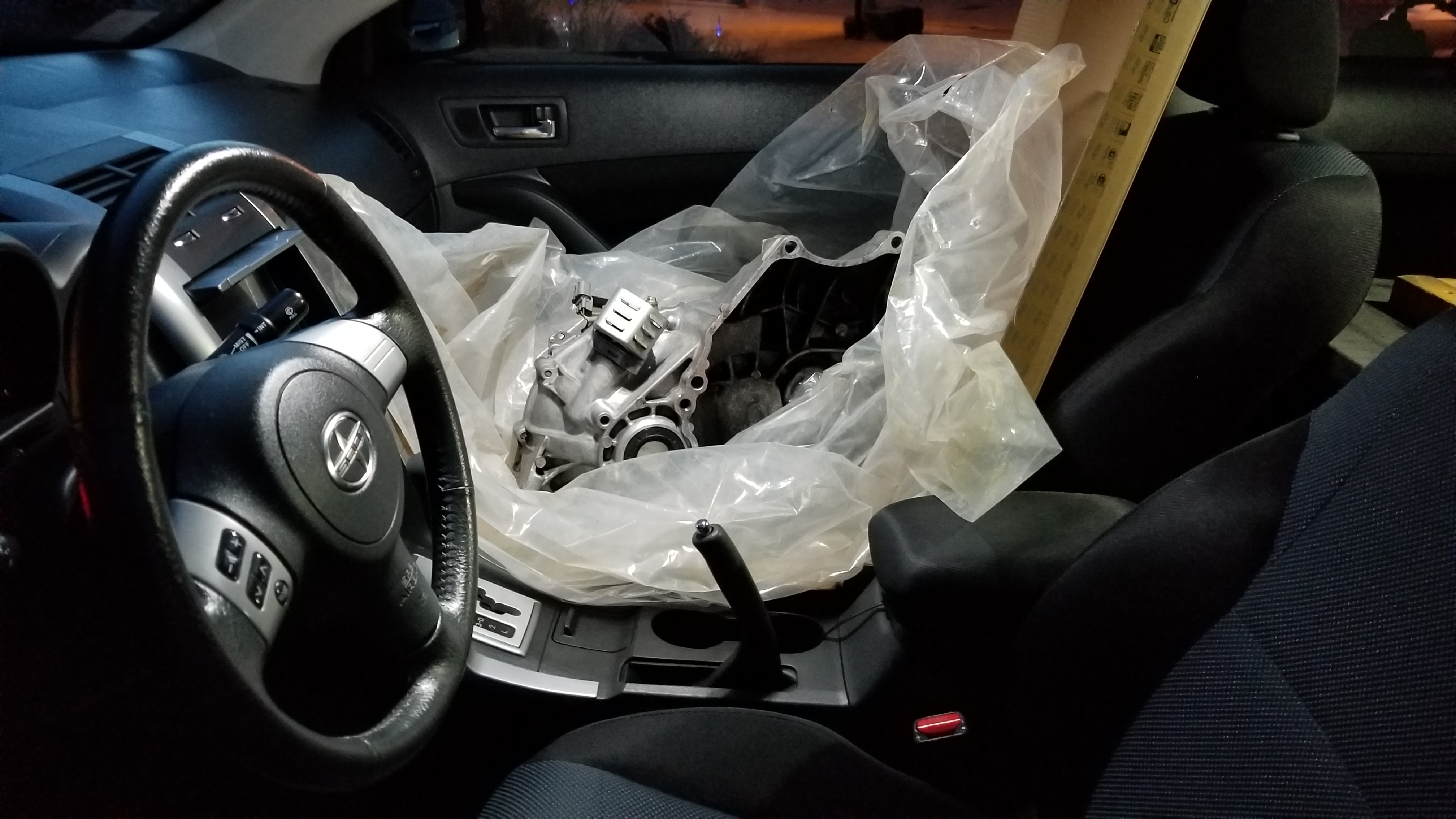
Put it on a furniture dolly to make it easy to move around. I was barely able to lift it out of my car seat onto the dolly right below, definitely a two person job for anything besides a vertical lift. I can only imagine how much heavier the auto trans will be once I get that out...
ZLfd0yM.jpg


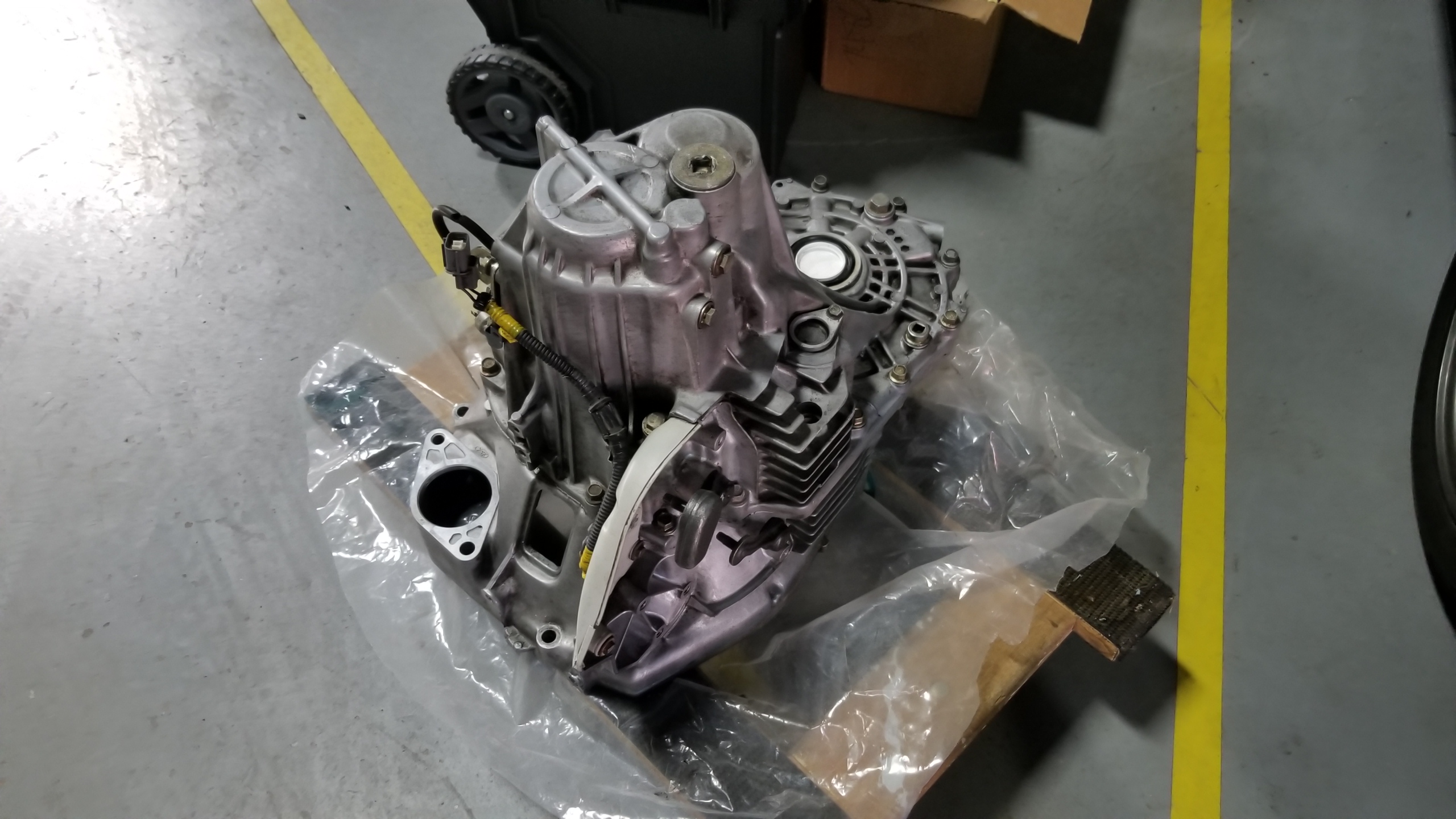
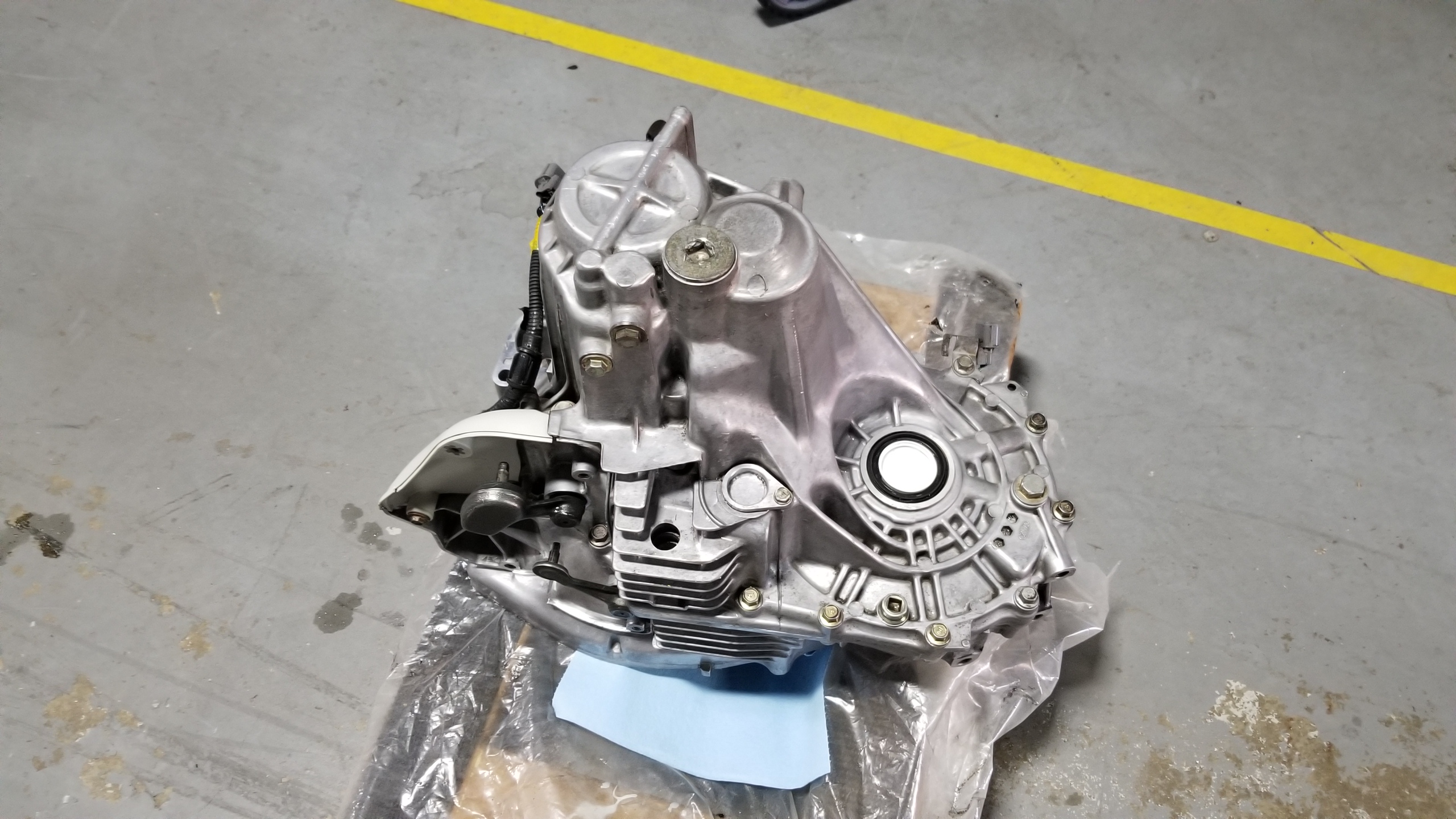
Before taking it apart, I spent an hour or two cleaning off the outside to get rid of the leftover oil, debris, and little pebbles wedged into the casting. Brakleen worked well to remove old grease but also seemed to dull the case metals a bit, so I also used some normal citrus degreaser.
rdfNrTU.jpg


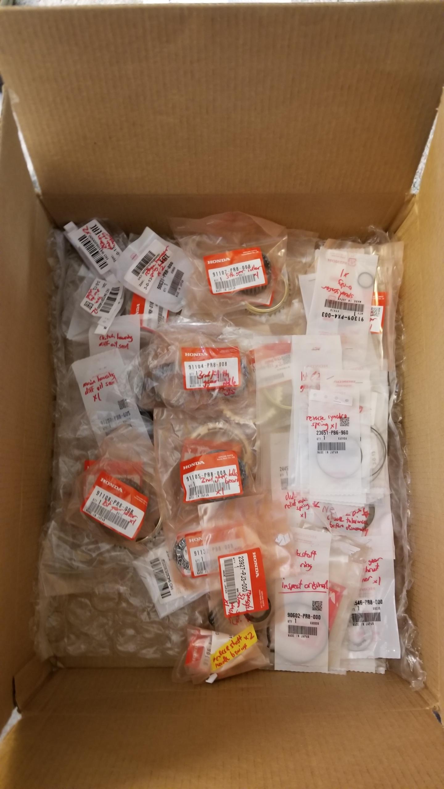
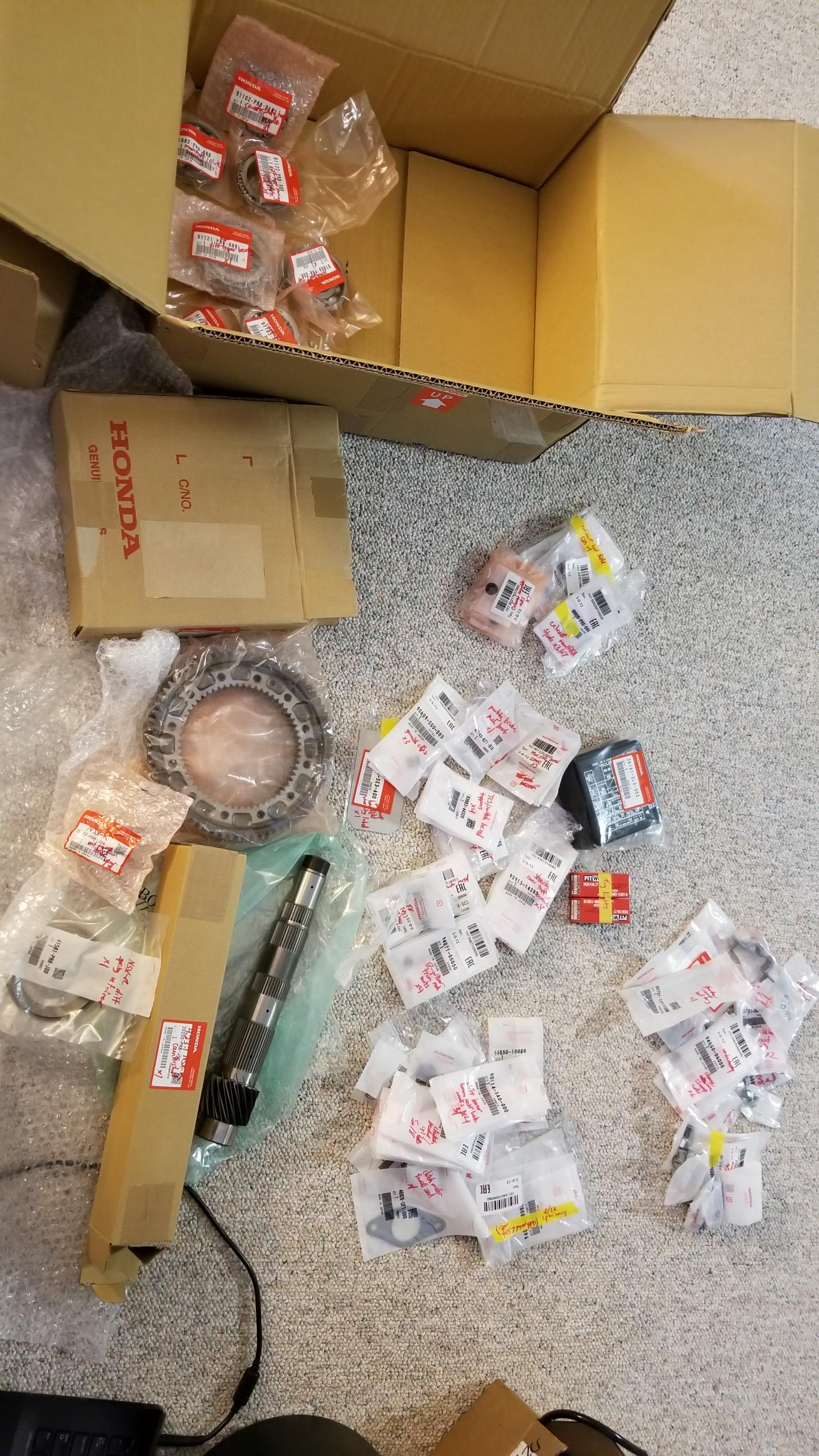
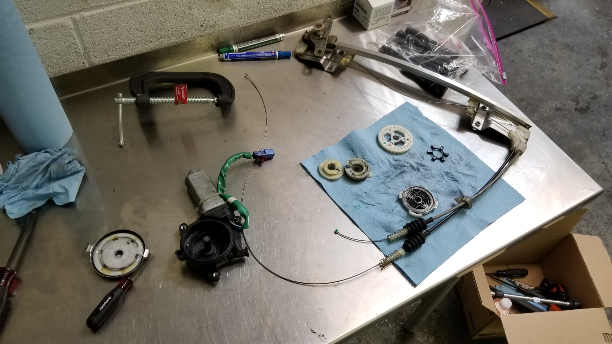
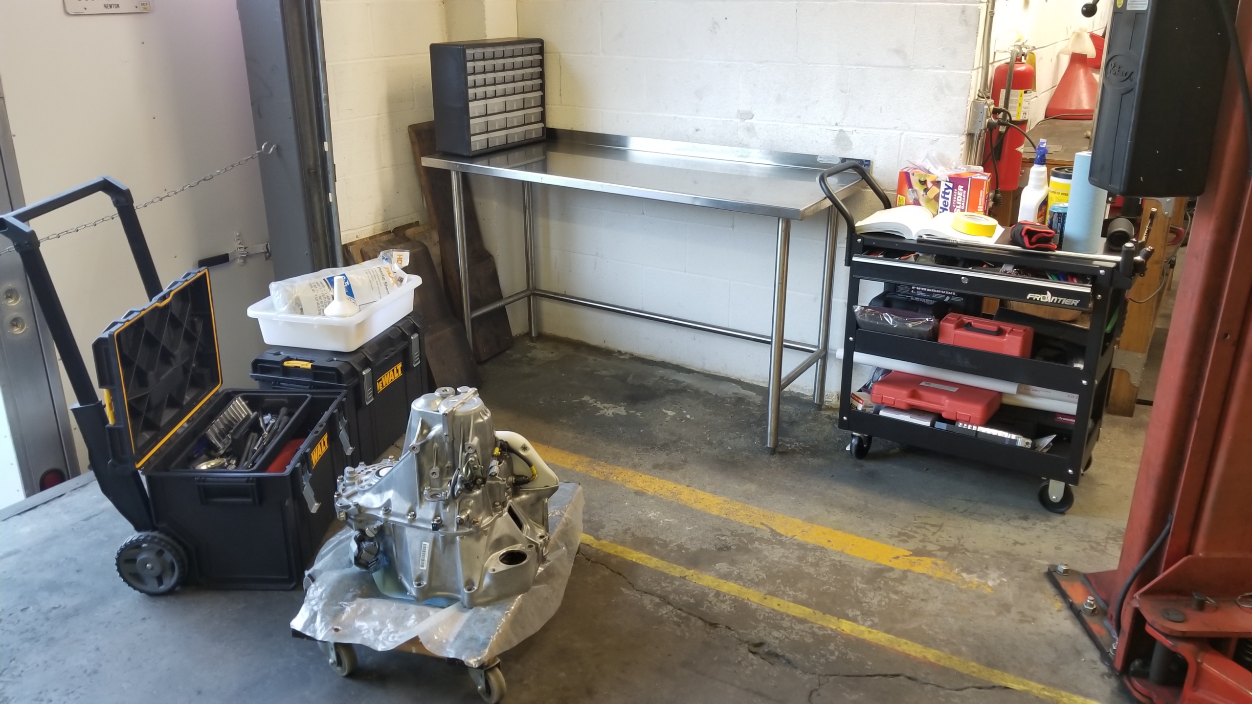
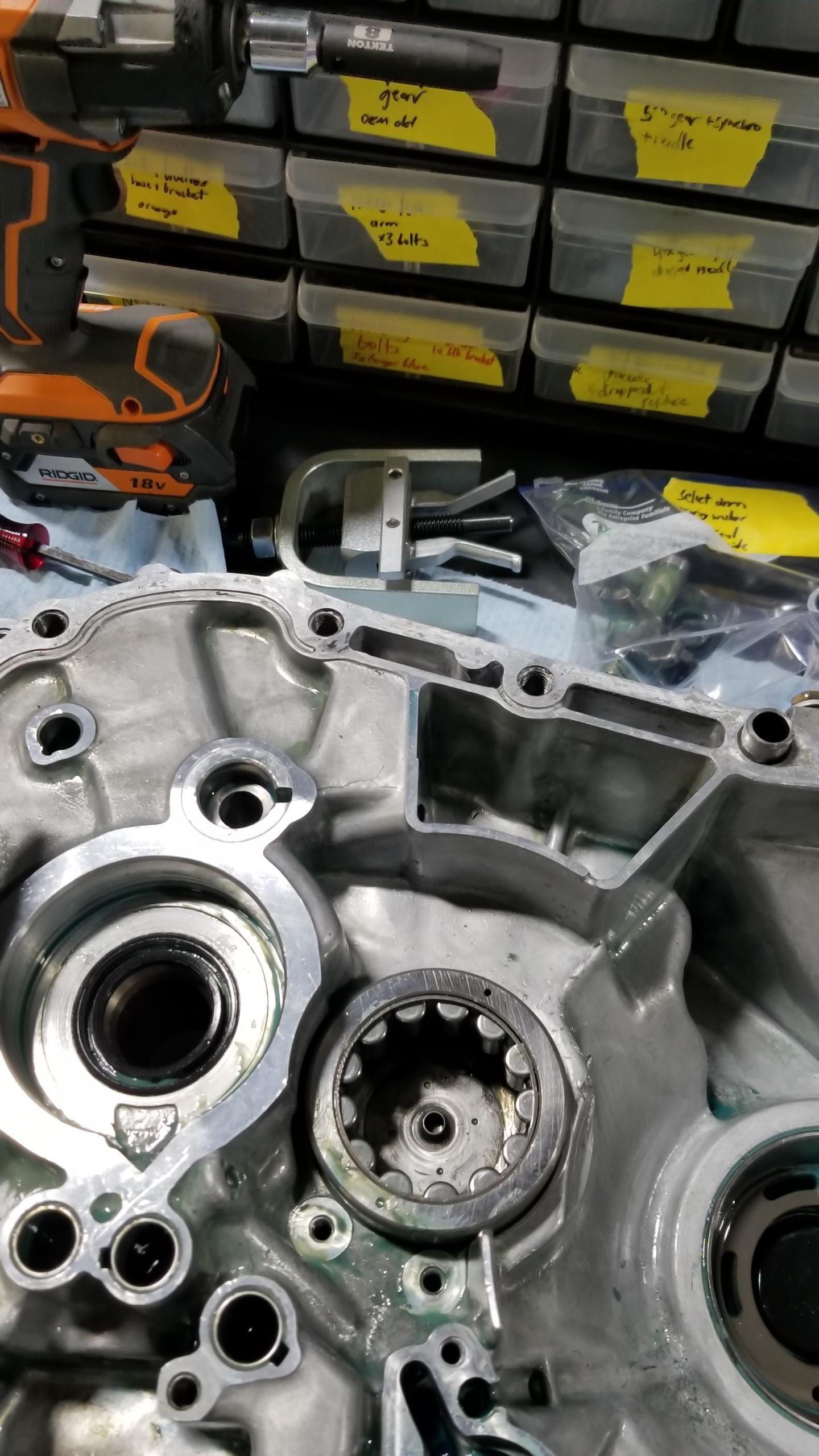
My little setup for the rebuild. It would be nice to keep everything here until I'm done, but I have to remain somewhat mobile so I don't hog the space too much from other people. Notice my organizer drawers that I'll use to store and label some misc parts during the rebuild. I got the idea from Ronald Finger during his Fiero rebuild here (https://www.youtube.com/channel/UCgvRHIimO6otkQ4Dcl_9YqQ). I recommend it if you like car rebuilding, which you probably do if you're reading this particular sentence buried deep in my car rebuilding thread.
ZGXGNpP.jpg


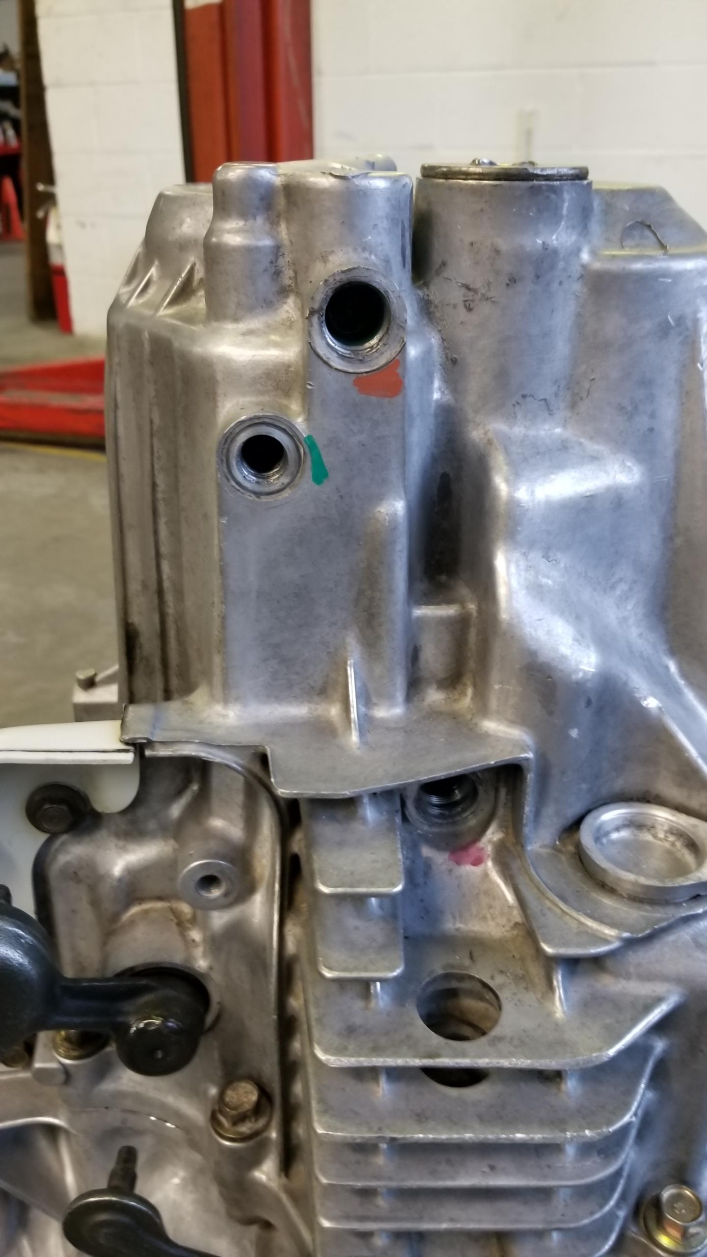
Taking things very slowly, I marked every bolt and sensor removed and labeled it before storage so I don't mix anything up. There are some ball detents for the shift forks that are specific to certain holes, a few sensors, wiring brackets, etc. to keep track of and using paint pens to mark the bolts and mounting spot makes it easy to remember where everything goes.
Ngioj1i.jpg


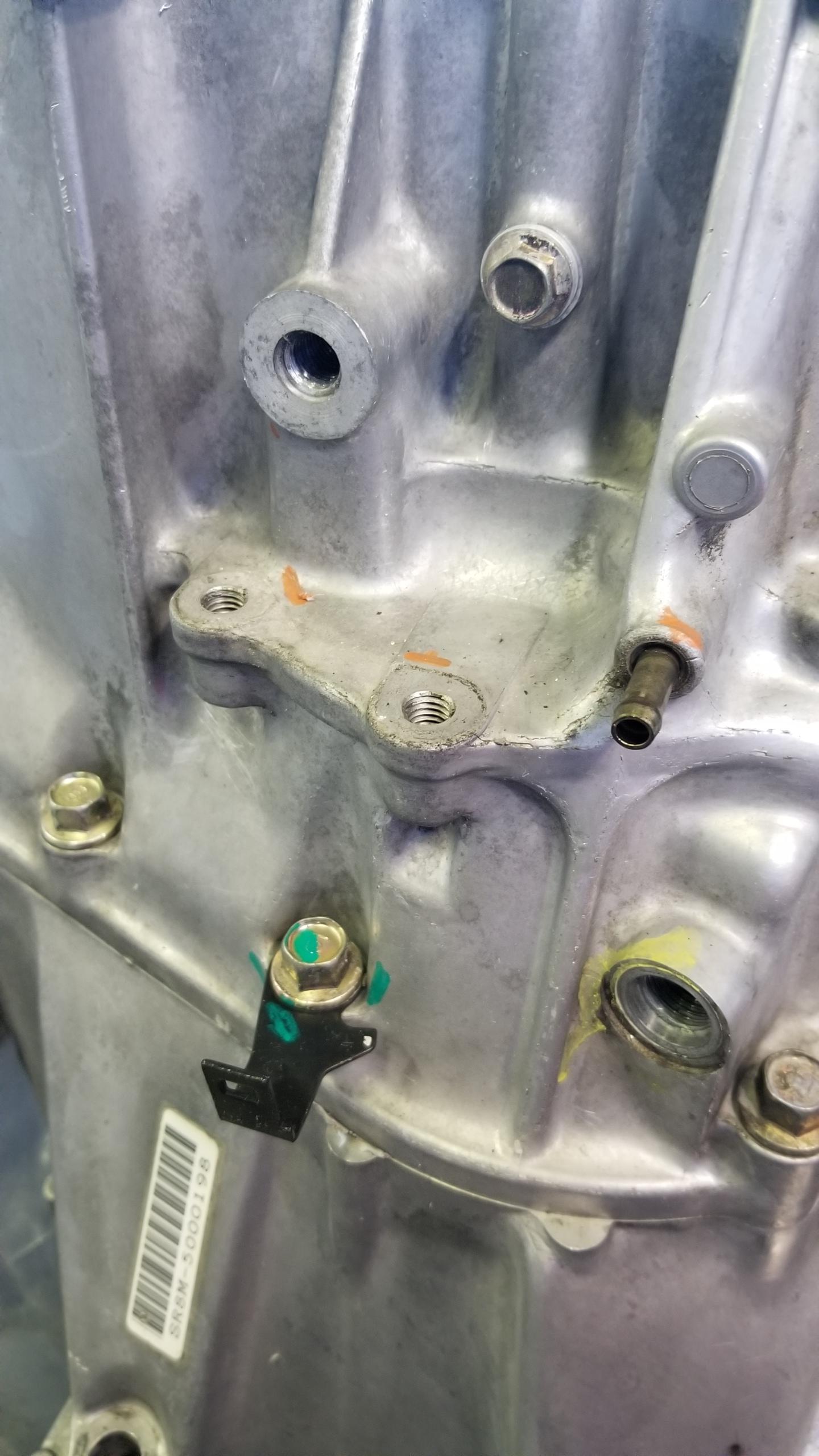
Other markings for brackets, breather tube, and stuff.
N48RLhg.jpg


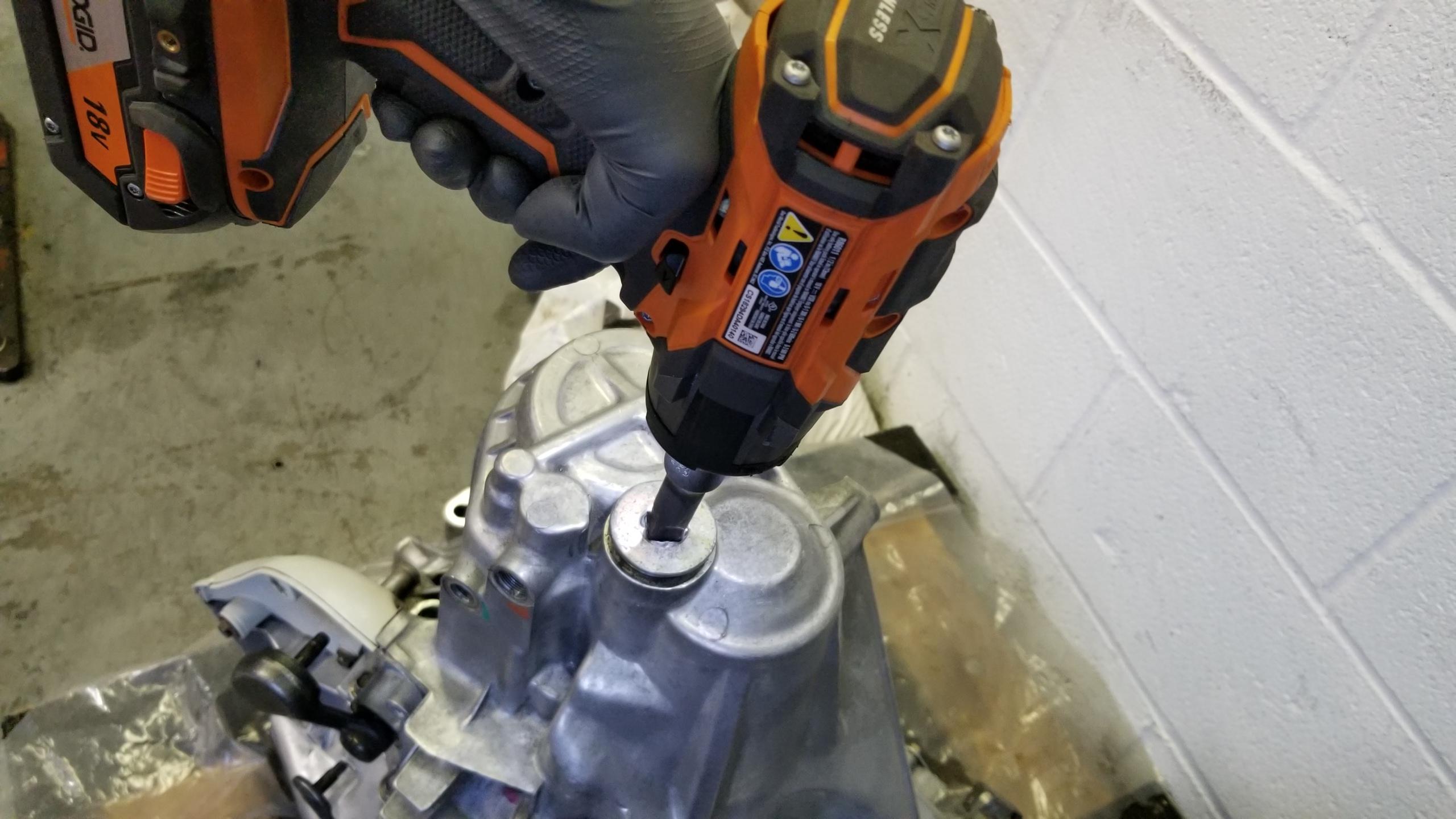
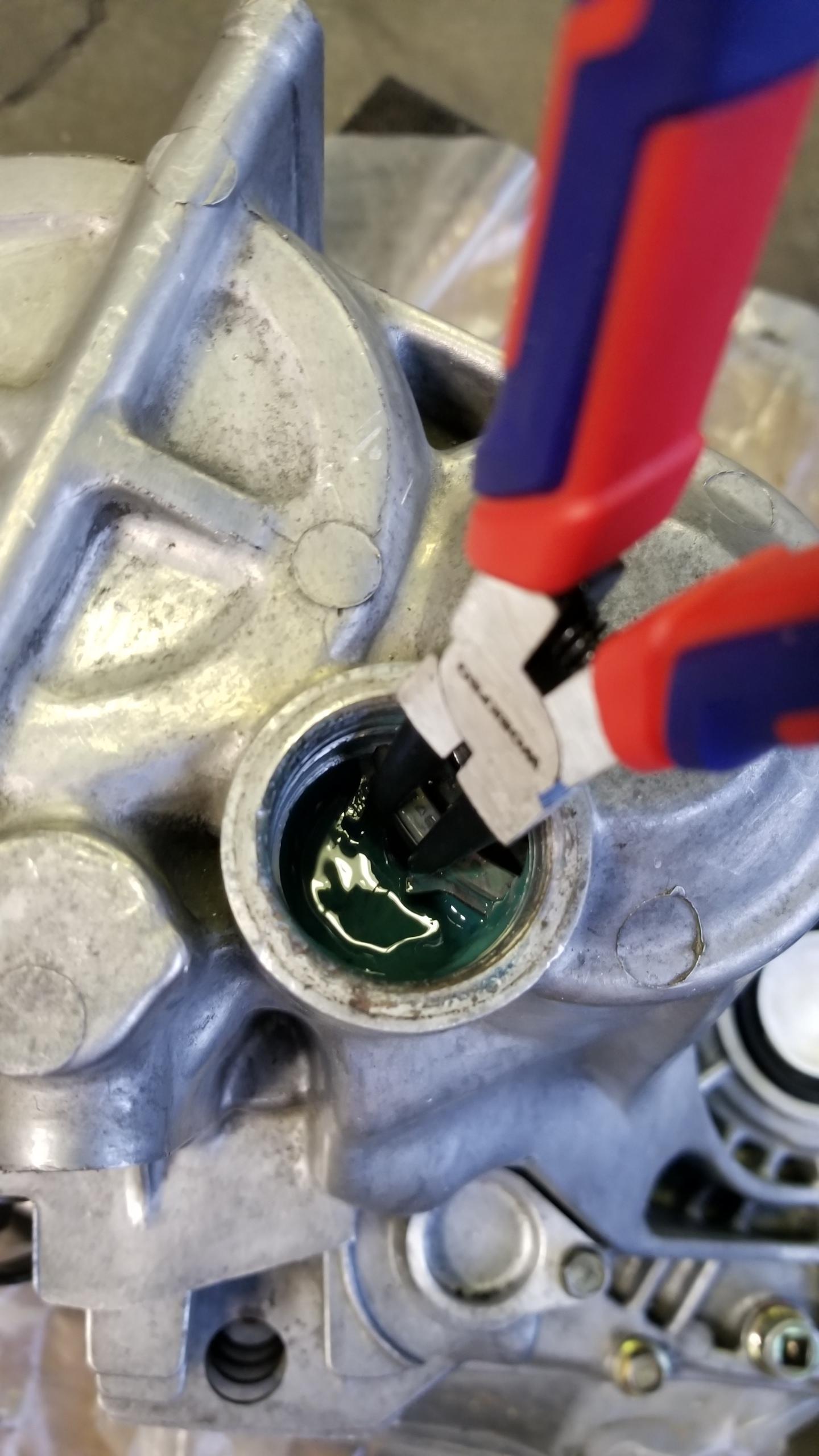
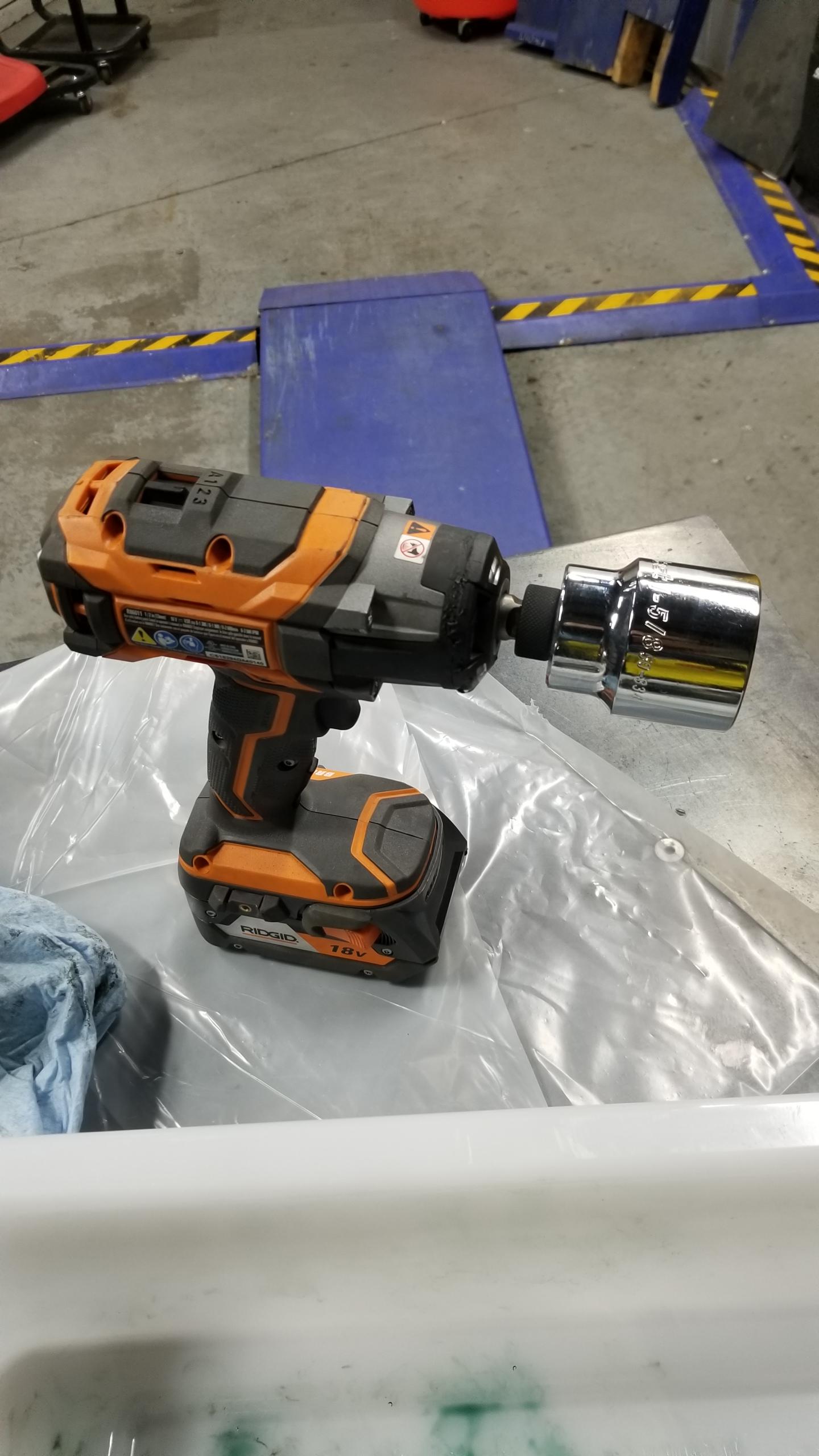
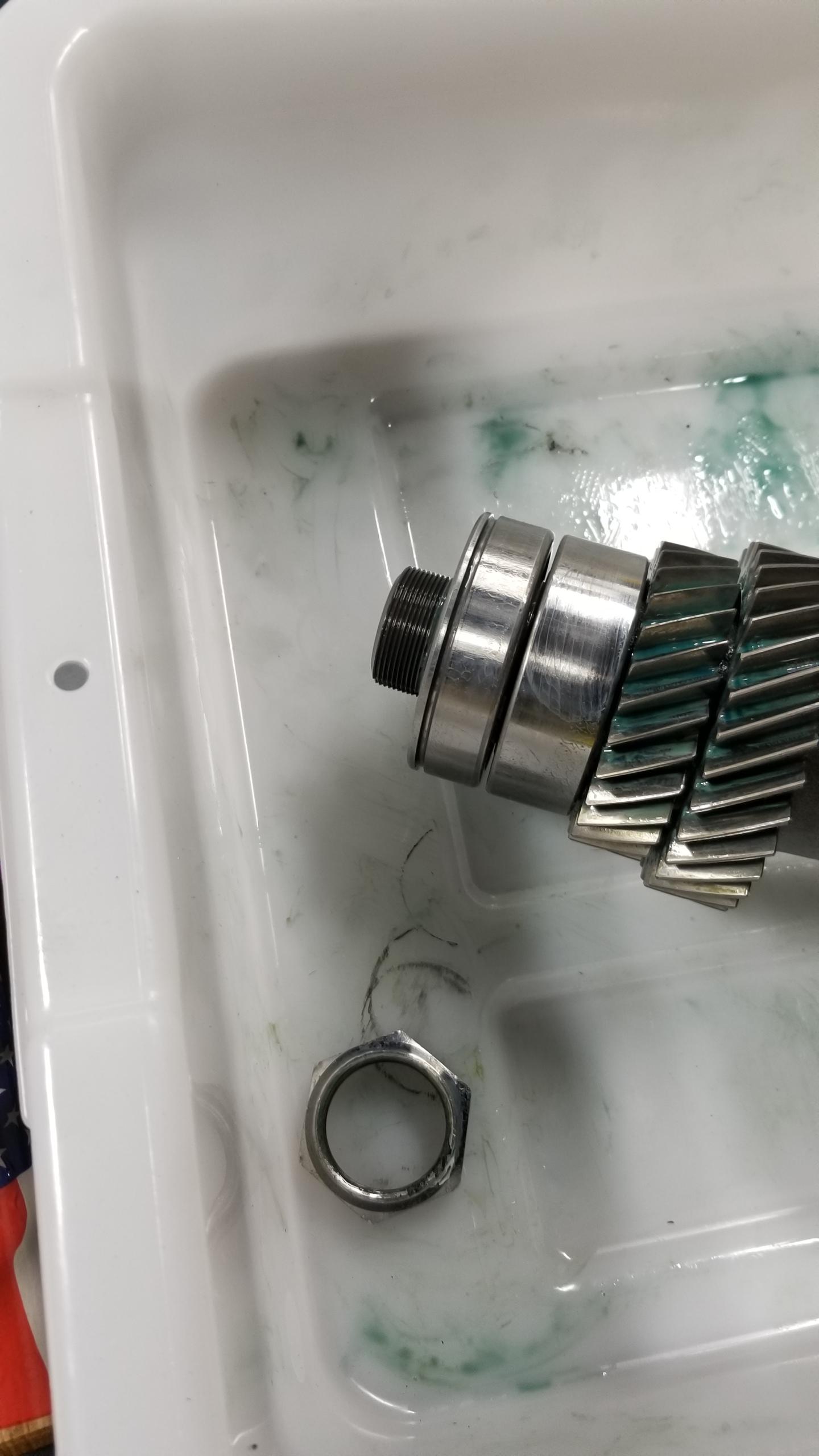
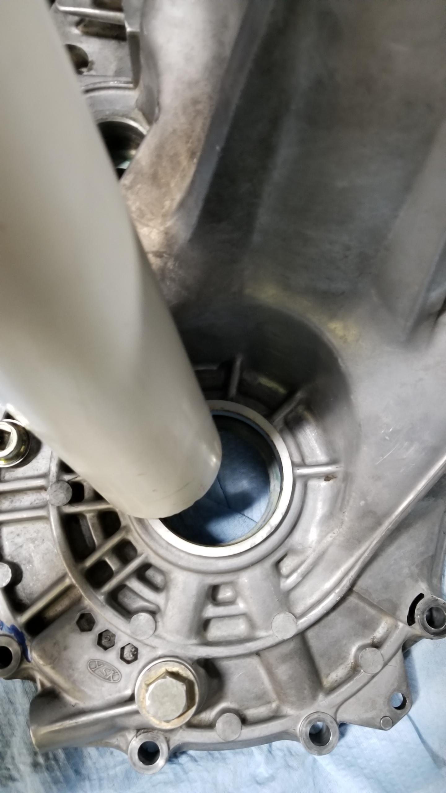
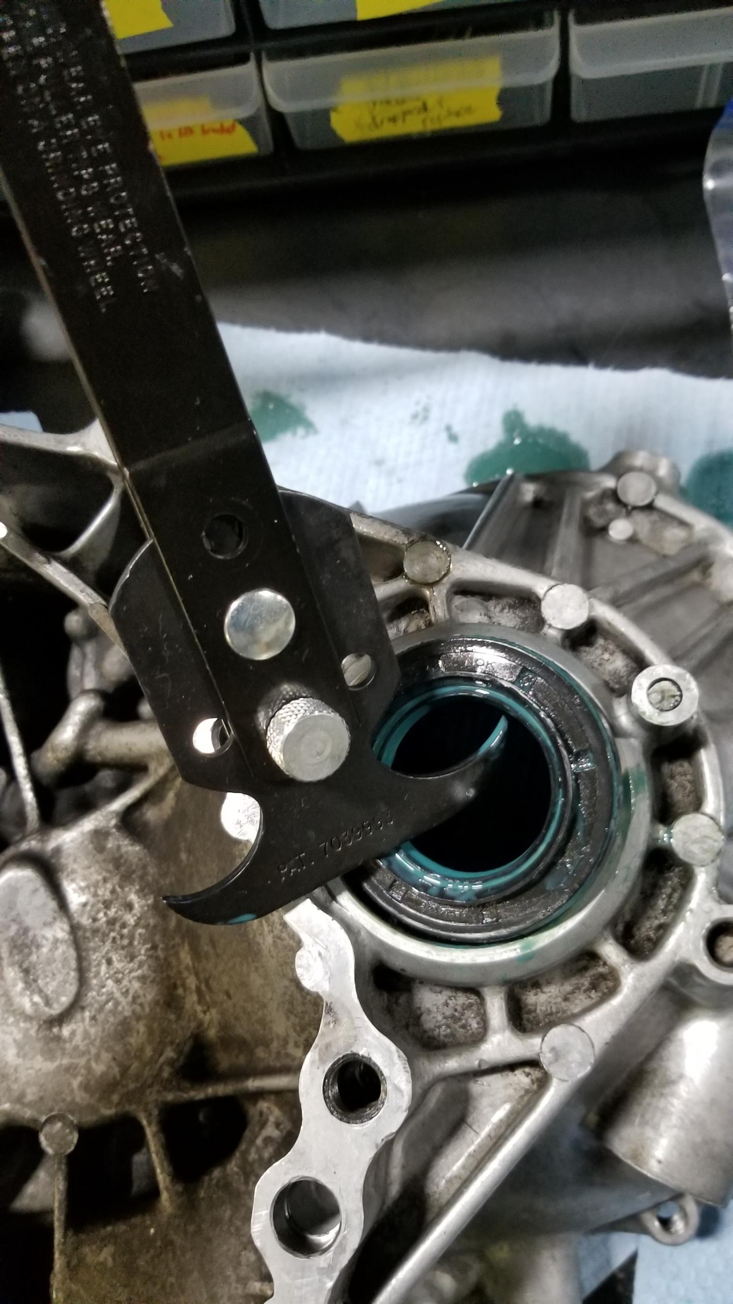
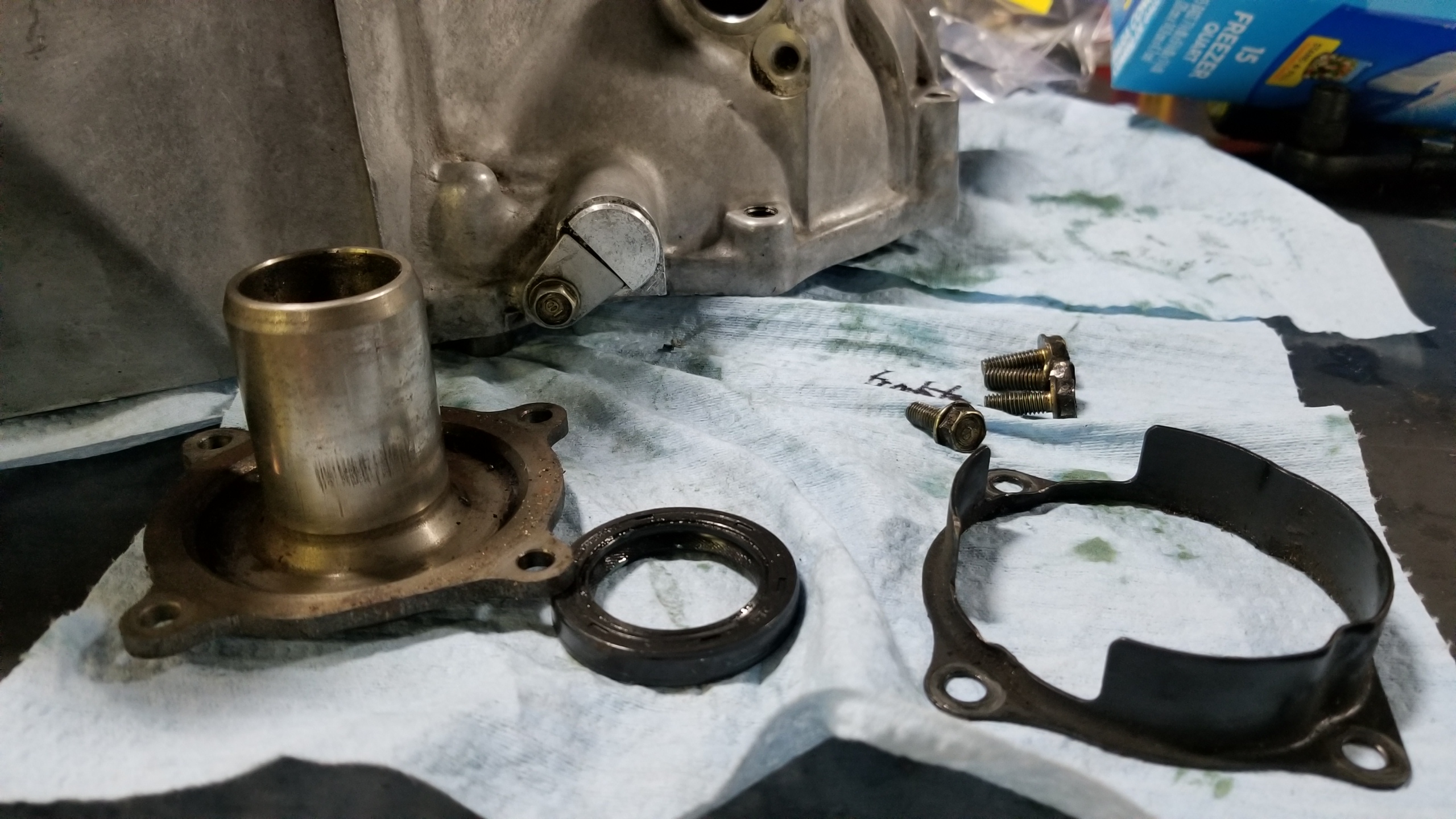
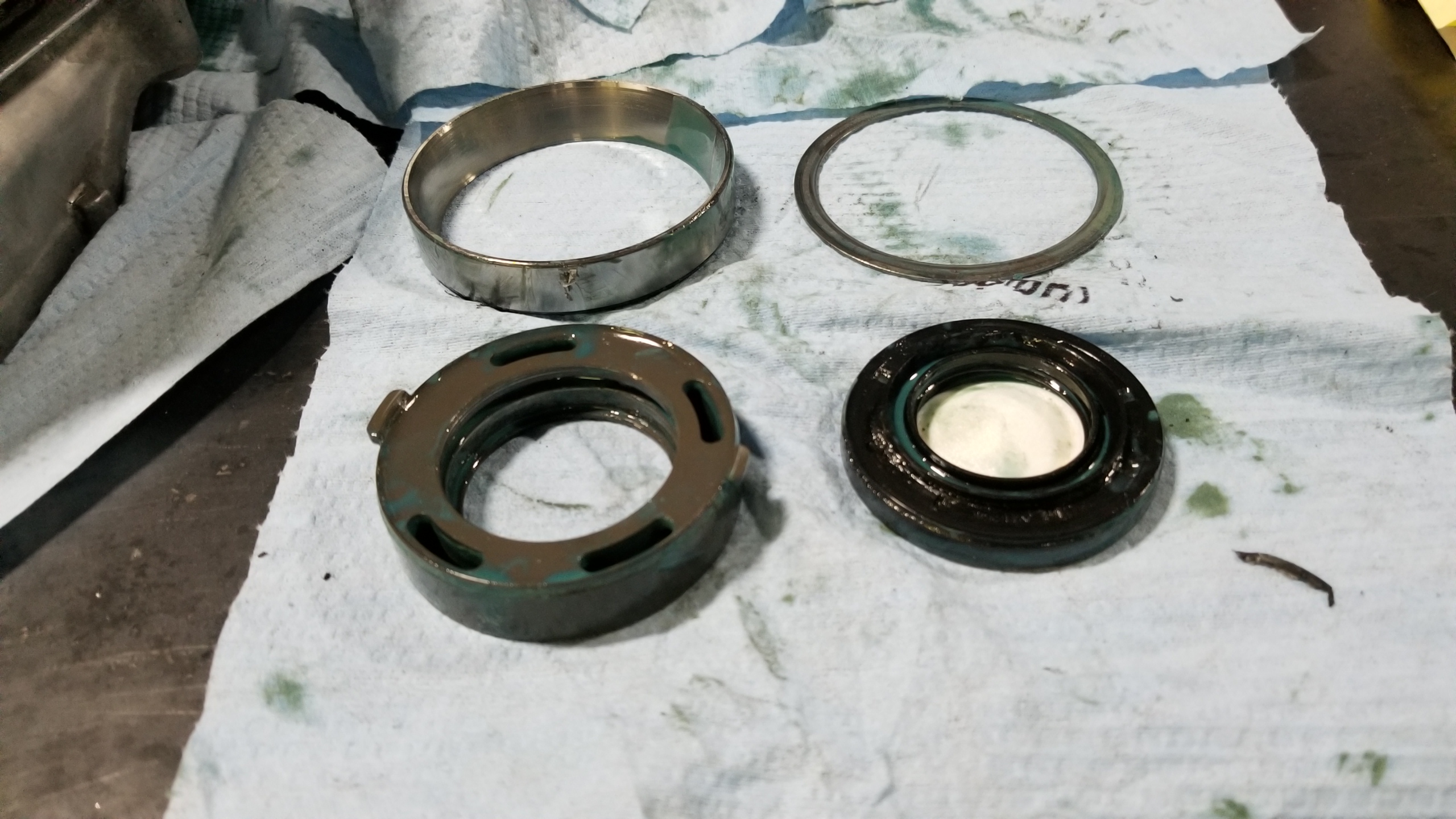
Once the sensors and outer case bolts were removed, I took off the big countershaft sealing bolt. It was already somewhat rounded from someone taking it off previously and my impact gun's snout made it worse, but using an extension with a more square face and some downward pressure allowed the bolt to spin off easily. I have a new one anyways, but it would be very un-fun to completely round this out without removing it first.
BdYMPXQ.jpg


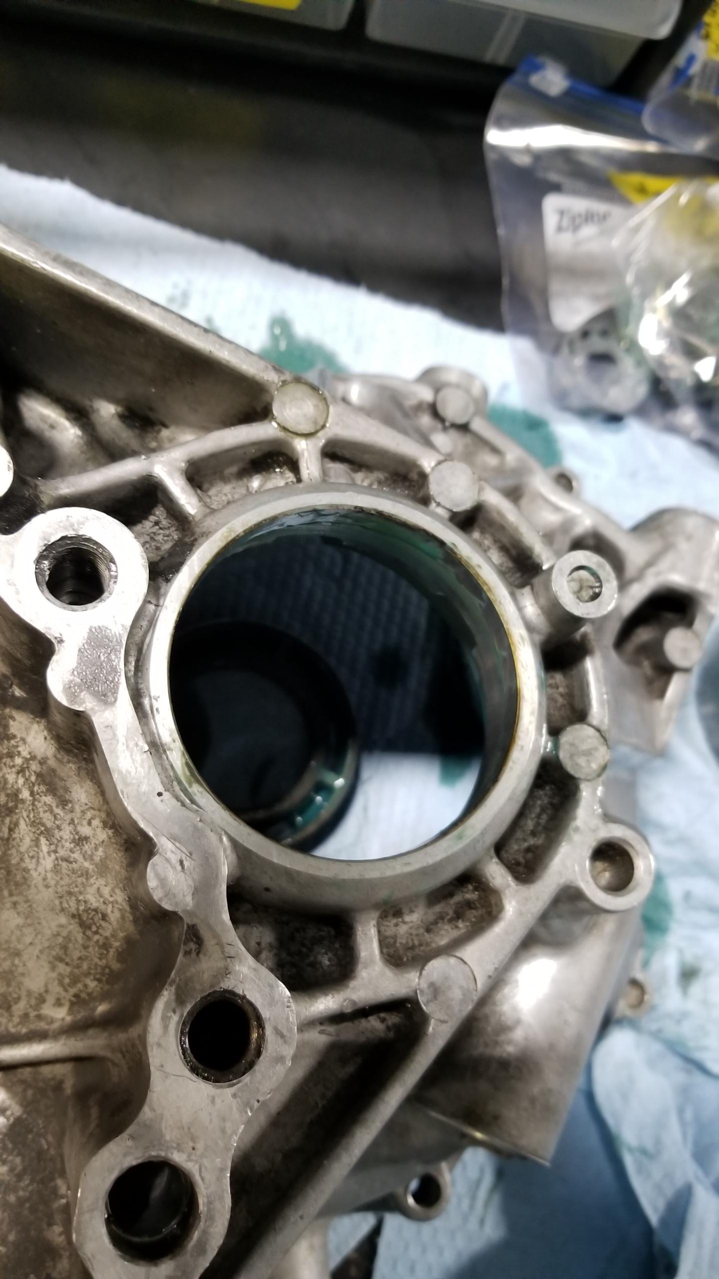
With the infamous countershaft snap ring exposed, I spread it open (a bit further than I thought was necessary) and allowed the countershaft to drop down past the snap ring groove in order to continue opening the case halves. I'm sure this will be challenging to seat back in the groove during reassembly since the countershaft has to come back up against gravity to line the bearing groove up with the snap ring.
bgN9XXC.jpg


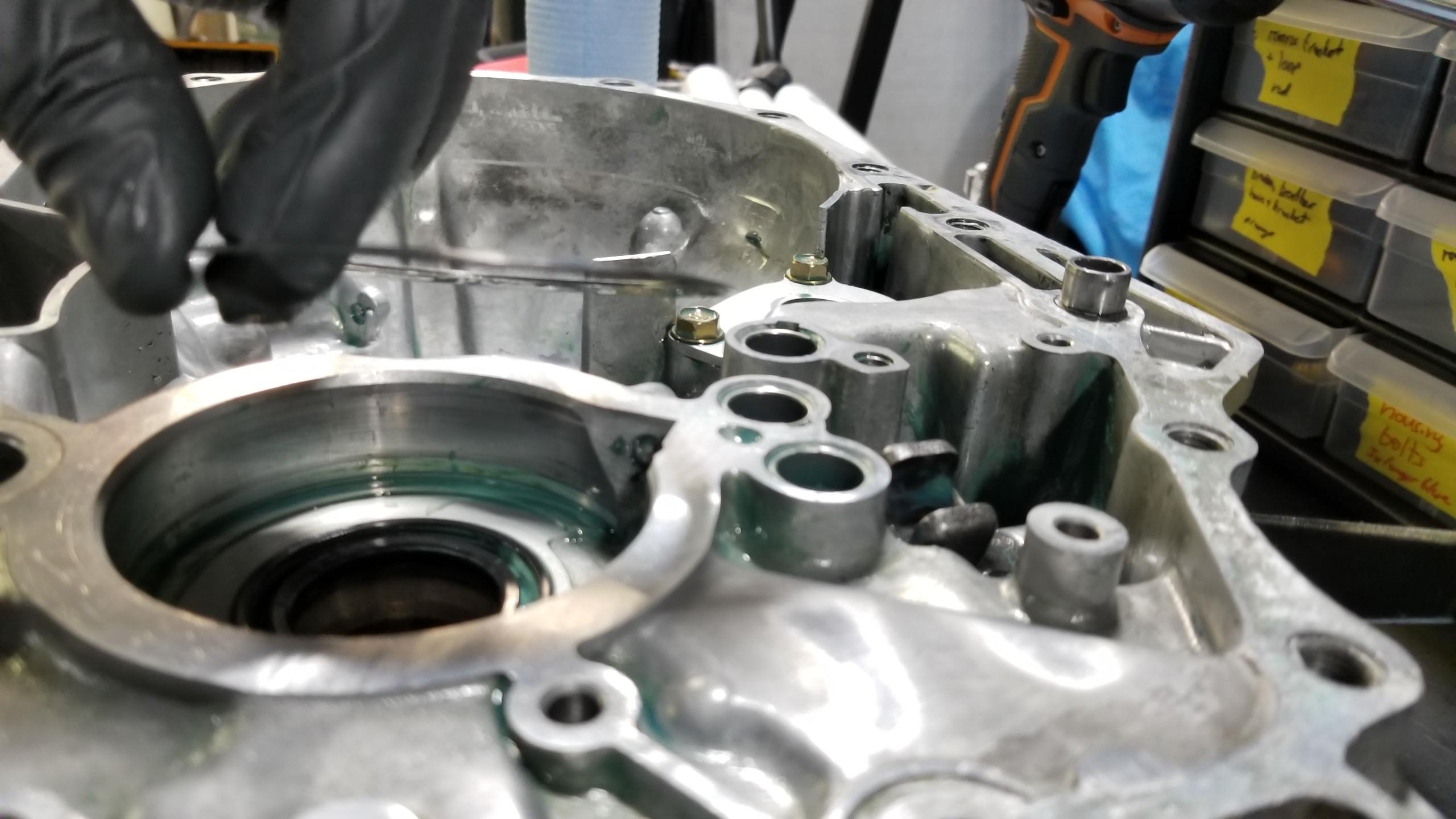
With that done and all the housing bolts removed in criss-cross stages, I wedged a pry tool in this little ear protrusion to split the sealant apart. I alternated between two sides to pull up evenly off the 4 dowels and avoided prying on the machined sealing surface so I didn't gouge it.
DSsOvDv.jpg


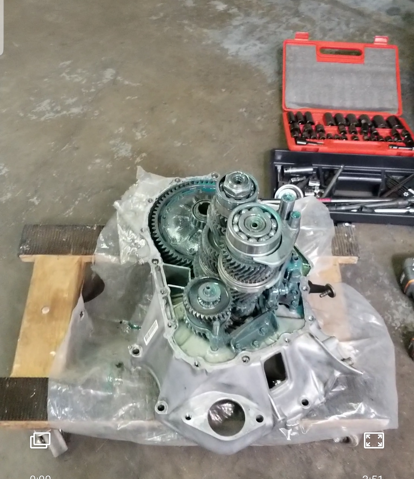
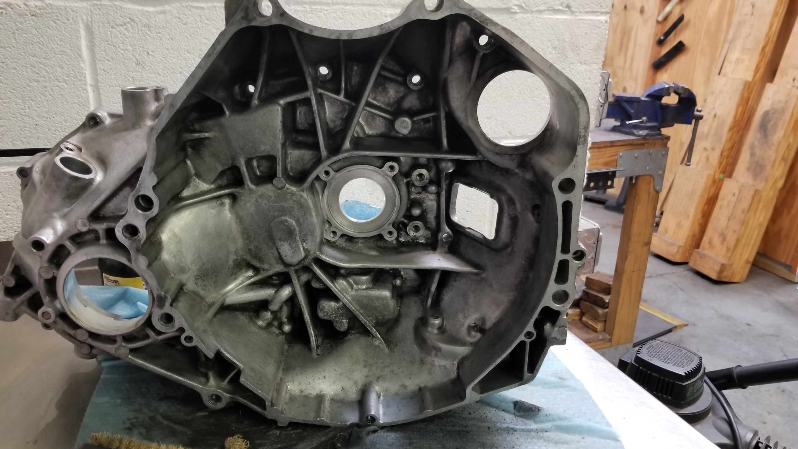
After some fudging around with pulling the upper case around, finally it came free to expose the trans internals for the first time. It looks like a Smurf was trapped inside during a track day because the previous fluid used was Redline Lightweight Shockproof gear oil which is this off-green/blue color. I'm planning on using Redline MTL based on some other discussion on Prime.
ZmHQ1MU.jpg


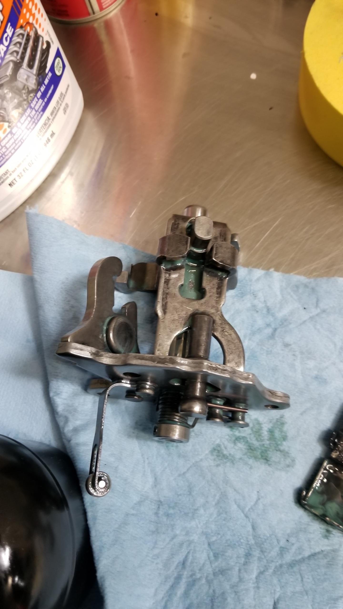
Shifter lever component thingy removed, and the not-pictured reverse shift lever assy. Just following the factory service manual at this point, and taking measurements in a few places with feeler gauges to see how the wear on the shift fingers, etc. are. So far they are all within the service limits.
QaYOv5h.jpg


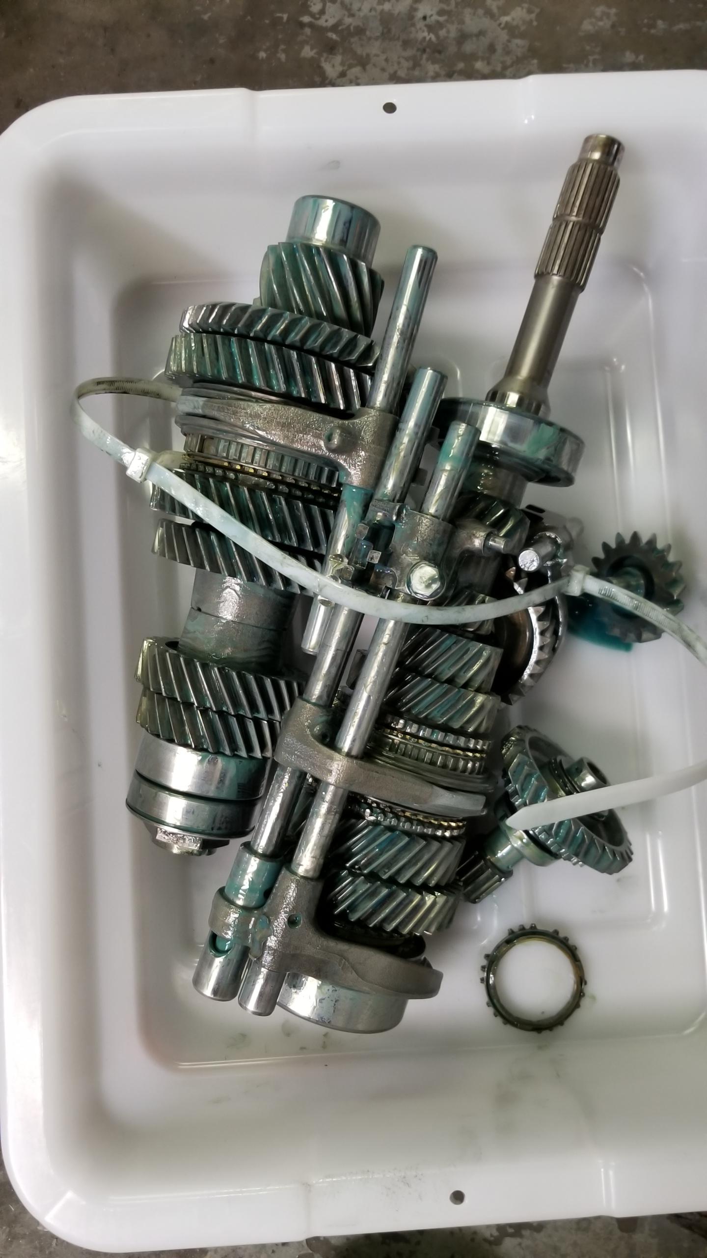
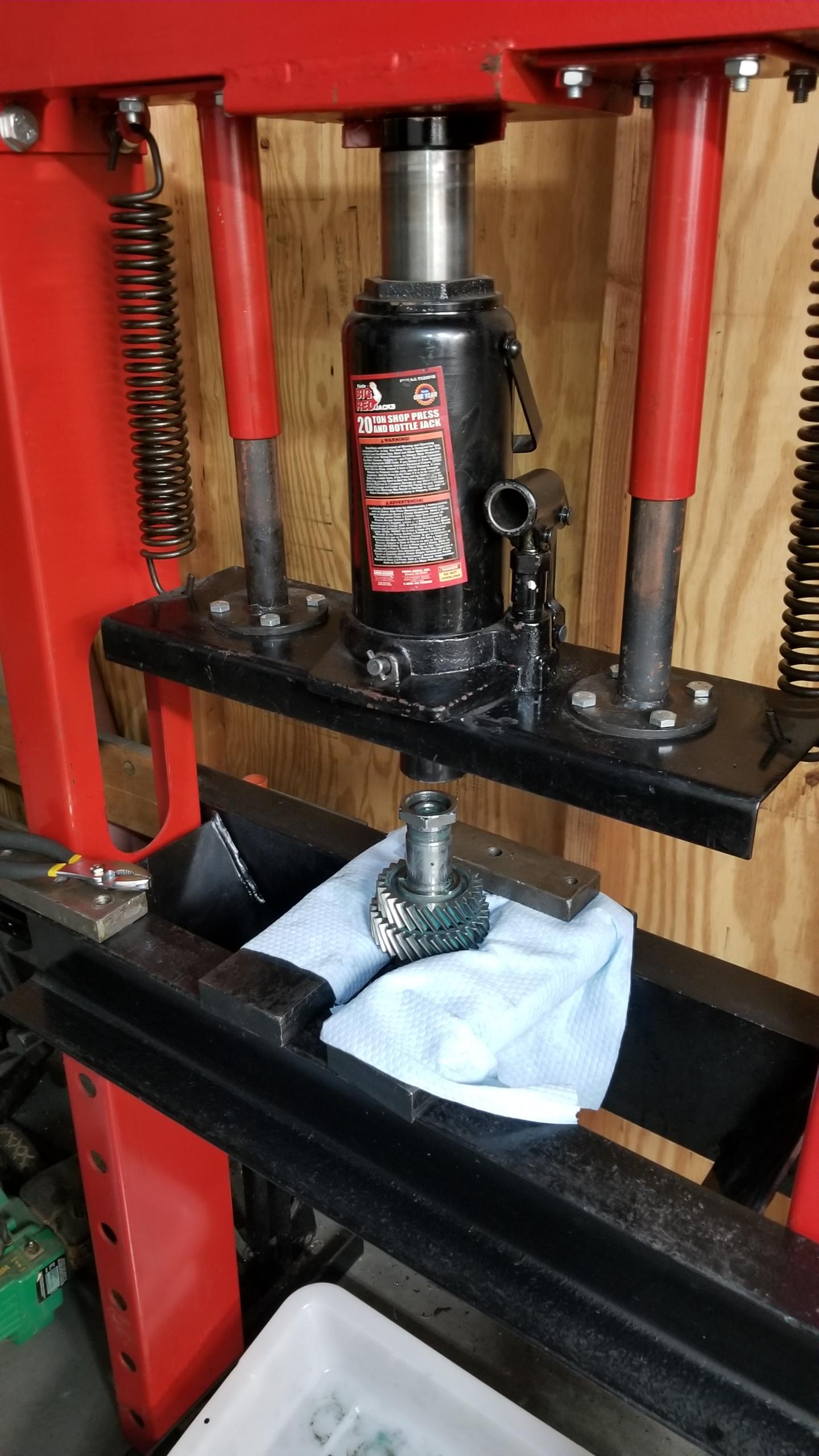
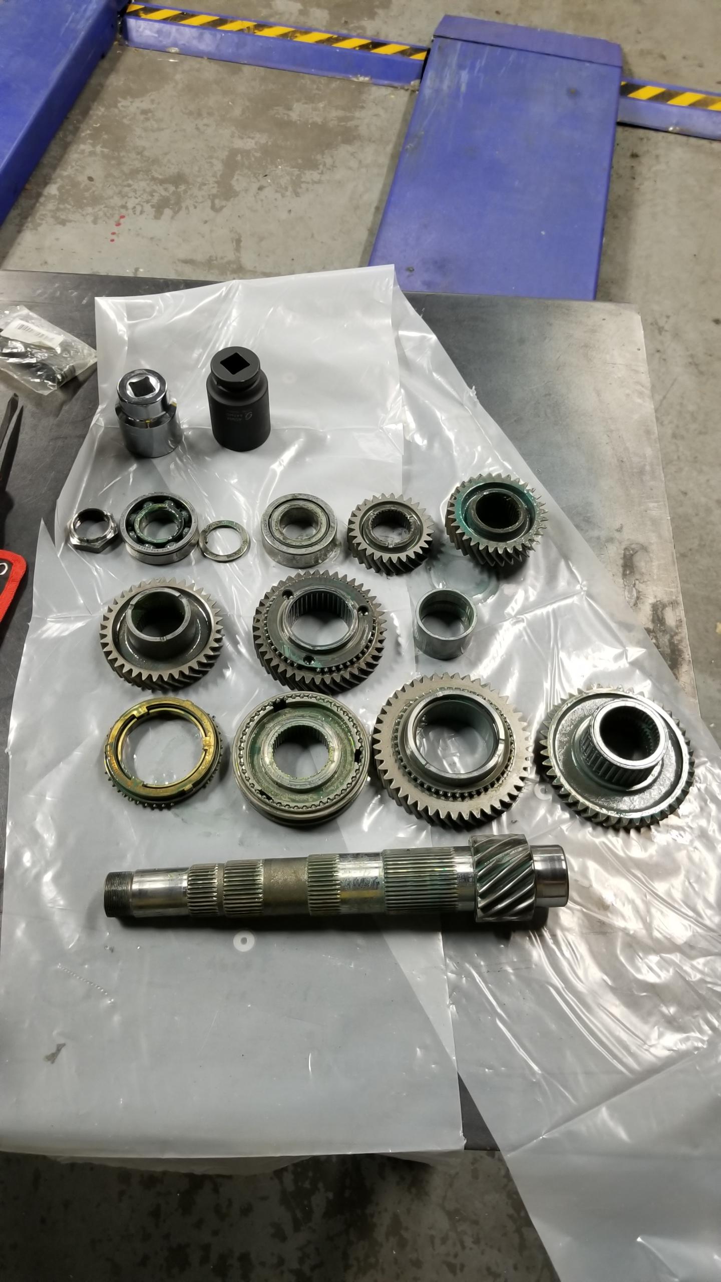
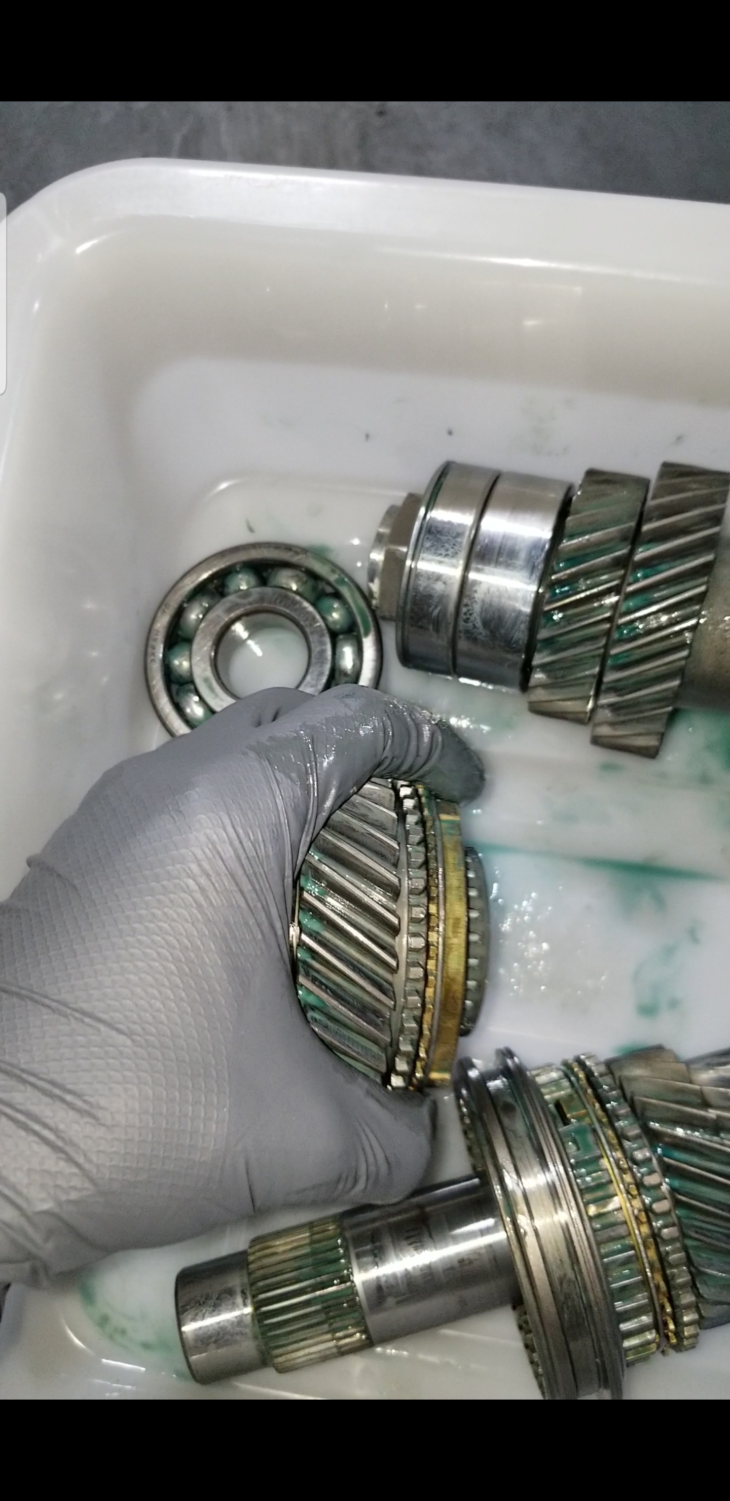
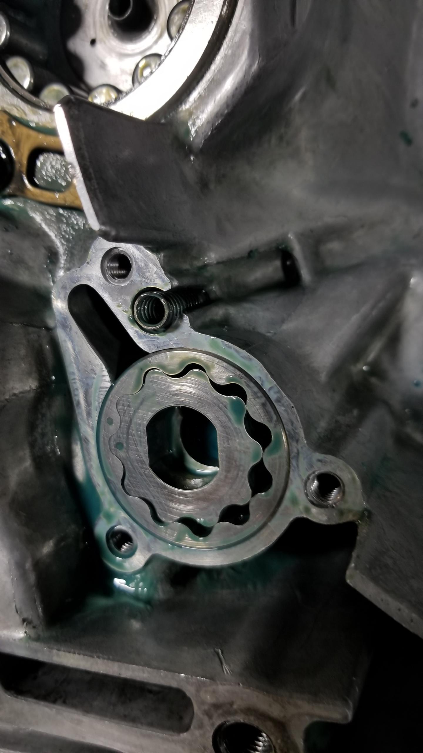
I used the zip-tie method to remove all 3 gear stacks at once. It would have been wise to use a second set of ties on the other end of the stack to provide more support, this group of gears is very heavy and it was a bit spooky lifting it all out of the trans into this new bin for disassembly & cleaning. I also removed the oil pump drive gear since it's a slip fit. A few of the items on the mainshaft also wanted to slide off since they're also mostly (or entirely) slip fit.
7k7NPWU.jpg


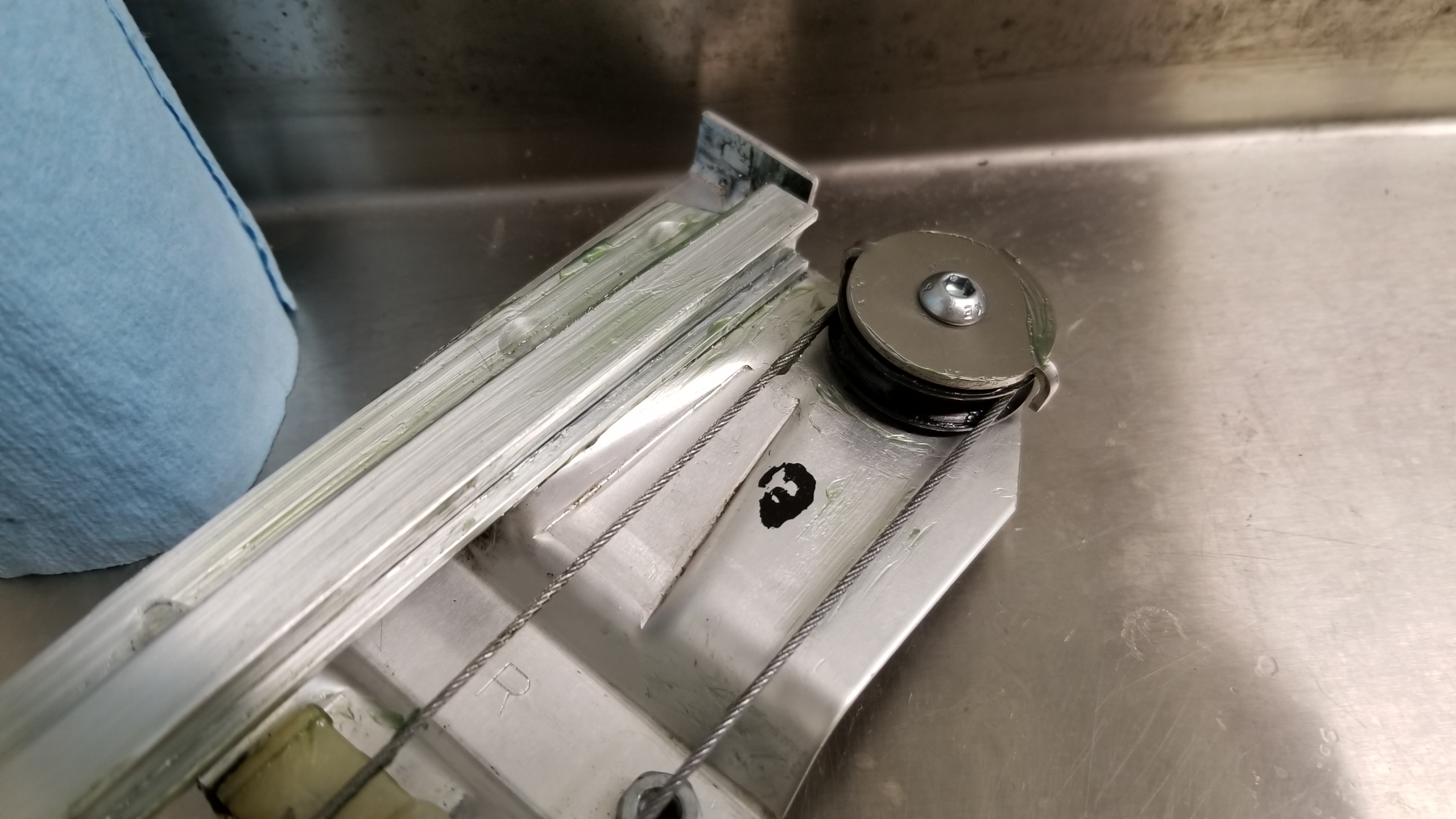
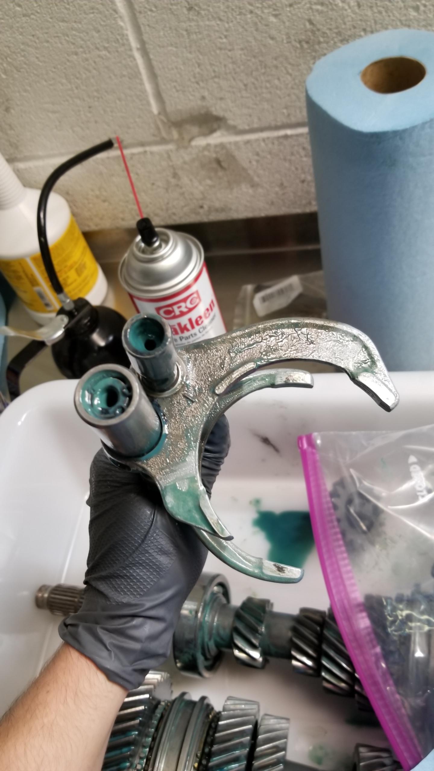
Here's the 5th gear shift fork. I read on the NSX UK forums that there is an older design with a thinner fork which has deformed in the past and caused 5th gear issues, but fortunately this one seems to be the updated design with the beefier ends so I don't have to mess with it. I would say the clearance between the fork and sleeve being ~0.80mm is a big higher than I'd like but still within the service limit of 1.00mm if I remember right.
vTYczxD.jpg


You might be thinking that everything seems to be going pretty well for one afternoon of a first-time trans rebuild, I thought so too since it was a bit easier than I had expected and I was making good progress. My goal was to get the diff out and take it apart to see which version I bought.

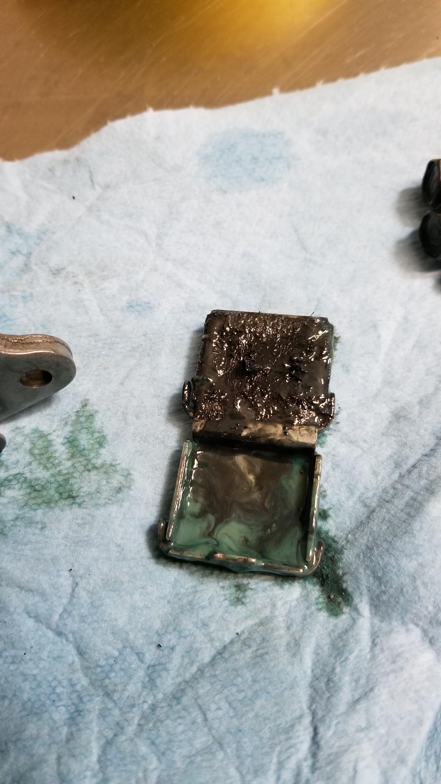
Once I got to the trans magnet, I found this massive shard of metal stuck to it. I would say this surpasses the "meh that'll probably be fine" category and goes into the "shit's real fucked" category. I was in a bit of disbelief once I started looking for the shard's origins so I was surprisingly nonchalant about it until I started thinking about the damage it might have caused before being caught by the magnet.

Any guesses where it came from before you scroll? I thought about it initially and it looked too big/long to be from one of the main gear sets, so my money was on the diff ring gear or pinion gear/final drive. At least I hoped it was one of those.
AUDmHfx.jpg


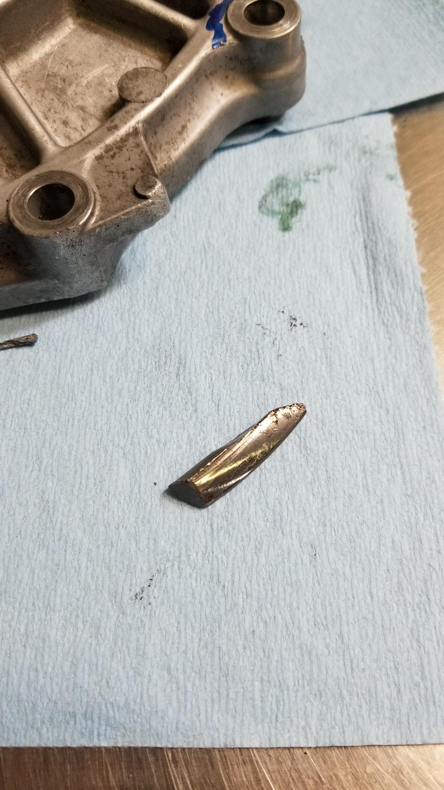
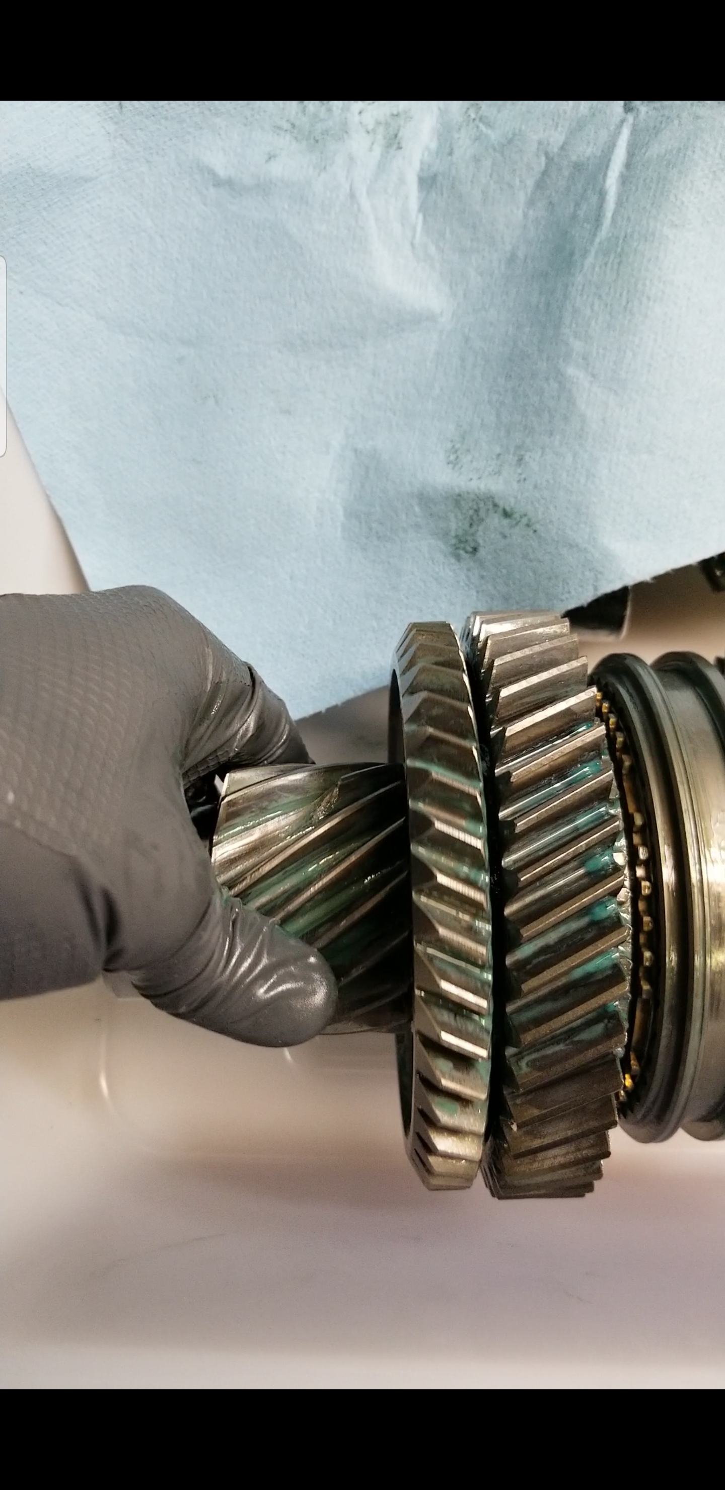
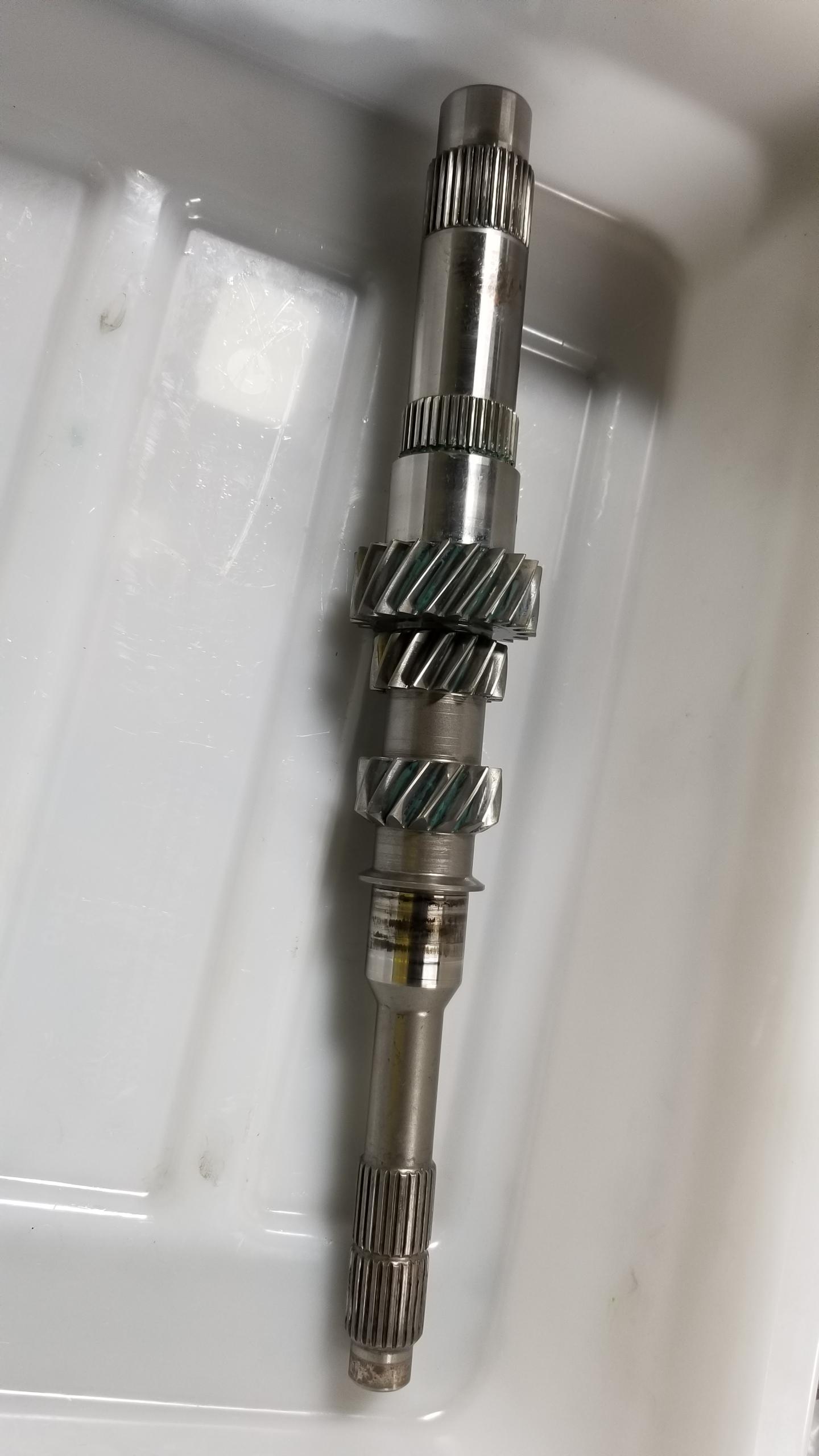
If you guessed the countershaft final drive/pinion gear, congratulations! That would be one almost entire tooth missing. Now, I'm not exactly in the "in-crowd" of manual transmission rebuilding but I don't recall reading any stories about a piece of the countershaft breaking off like this. There are other NSX problems like the 5th gear shift fork bending, 5th gear hub/sleeve wear, diff popping, and of course the snap ring failure, but I haven't heard of this one before. [MENTION=20267]sca037[/MENTION], I think I might have found the cause of your LSD "popping" noise :biggrin:. Or maybe not, I'm not an expert and this might not even be noticed during driving and might only cause some increased gear noise, though I'm sure the adjacent teeth would wear much faster too and eventually domino into stripping off the entire pinion gear.
zxbuI4d.jpg


Here's the magnet with the shard removed. Not hugely concerning if you discount the shard itself, but there were some small chunkier bits.
bjeTTSt.jpg


The real question becomes, how much damage did the broken tooth cause? Well, the answer seems pretty benign after some investigation. I closely examined the main/counter/reverse gear stacks (will go more in-depth during disassembly) and I noticed pretty much no wear at all on the gear teeth, so it doesn't seem like they were hit by the rogue shard. More pics will be posted in subsequent rebuild posts, but at first blush it seems like you could consider me "lucky" in that regard.

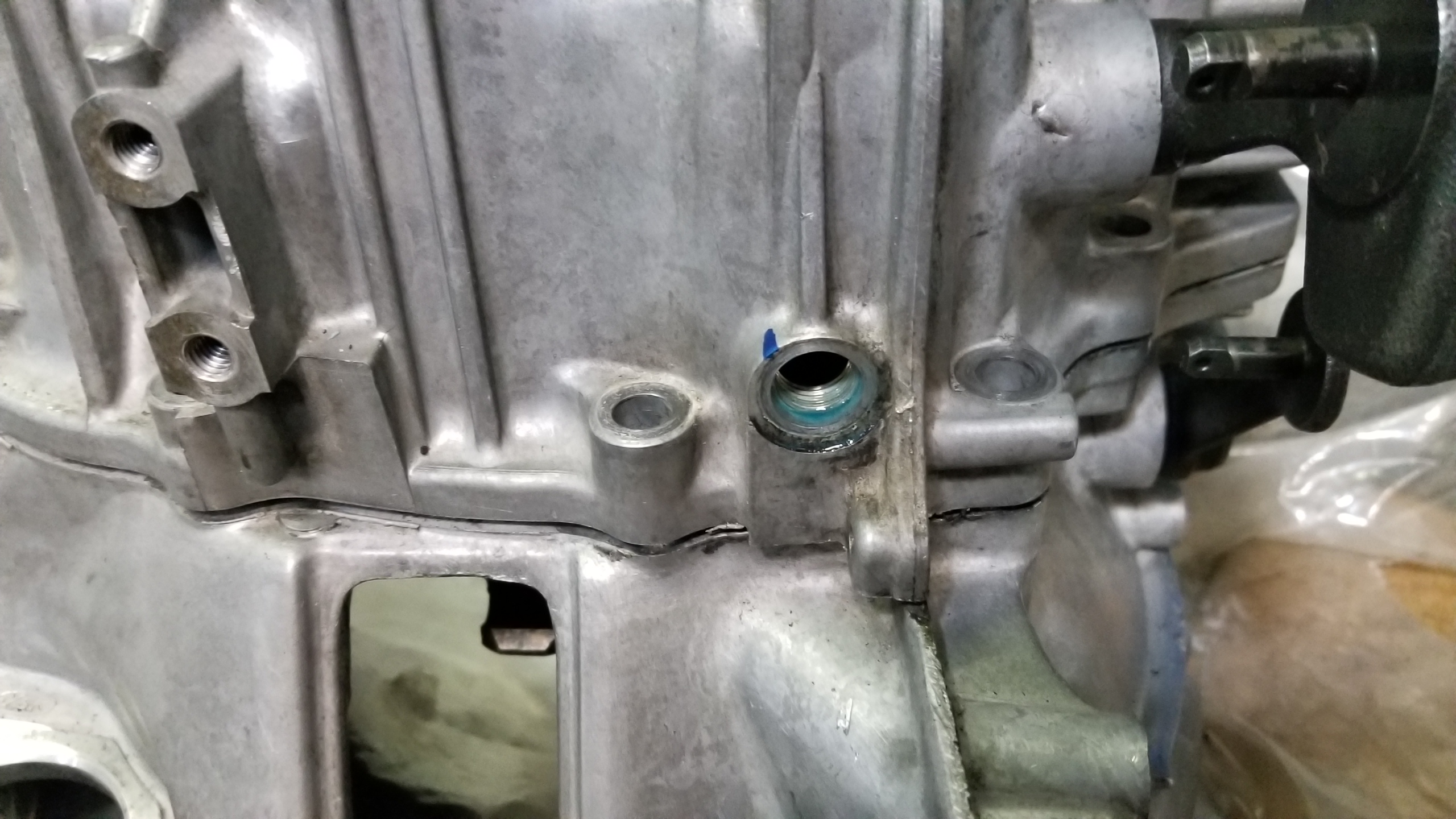
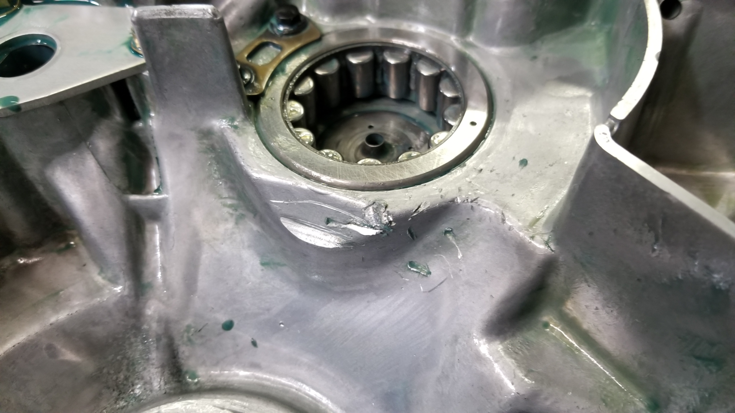
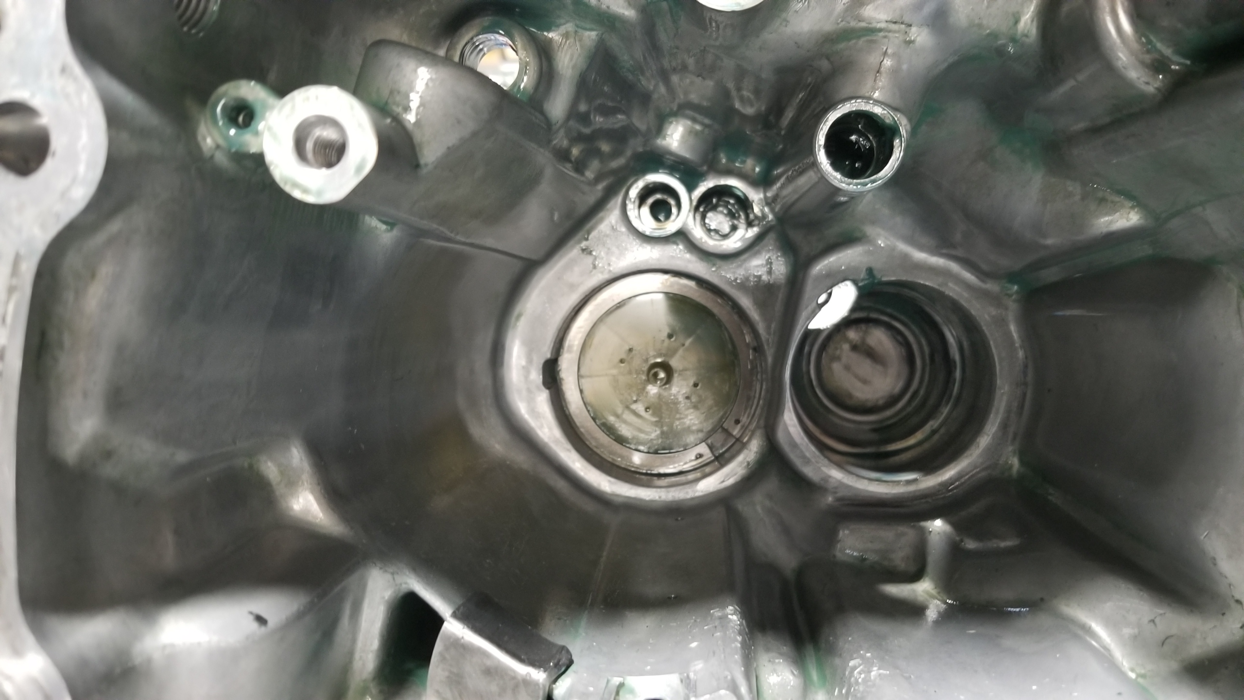
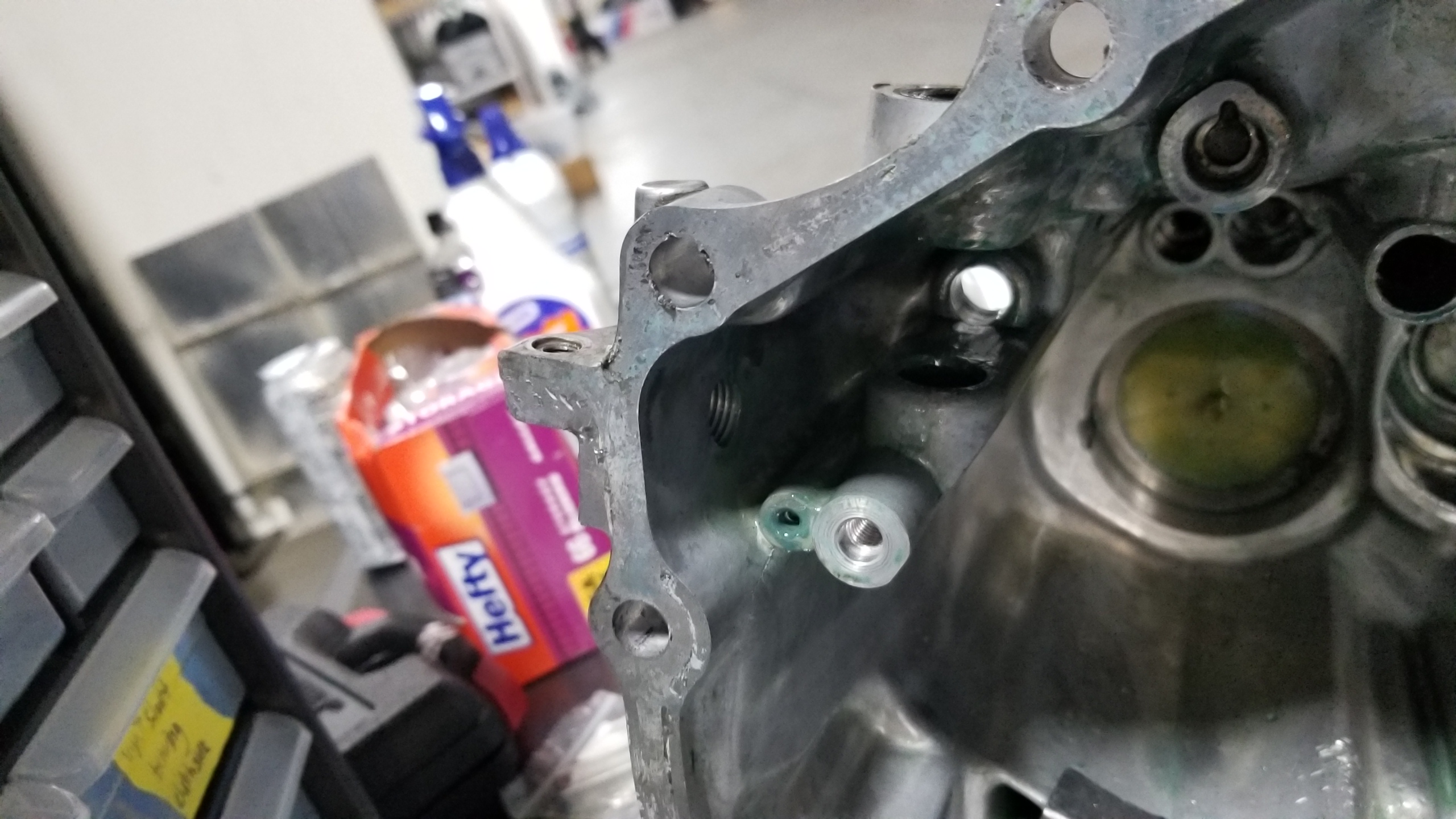
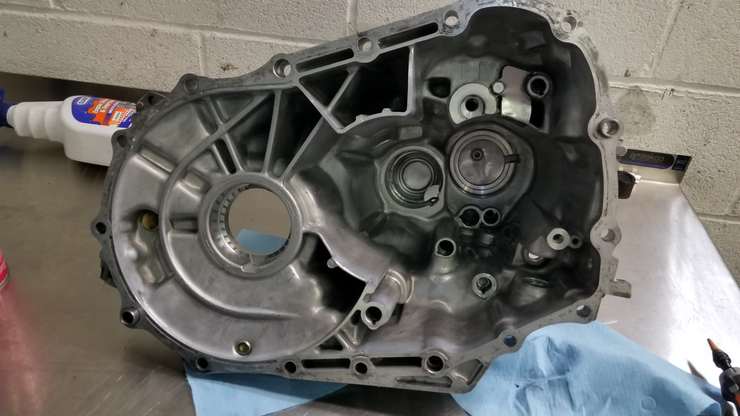
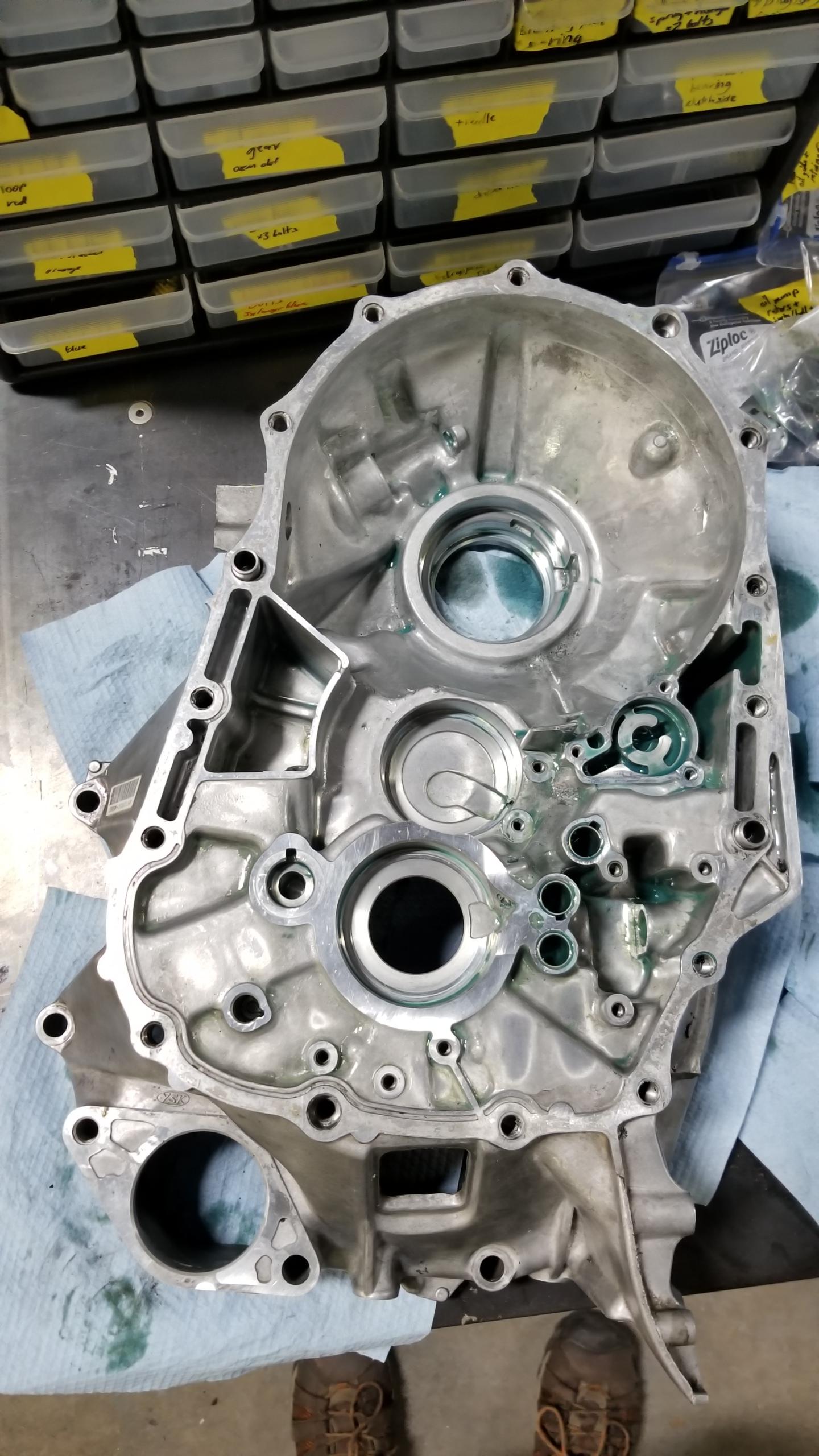
It would make sense the damage might be near the countershaft itself, and the inside of the casing near the diff certainly shows some scars on the soft (aluminum?) casing. This one was particularly noticeable, but I think after some filing down it shouldn't affect the operation of the trans.
YtXISX3.jpg


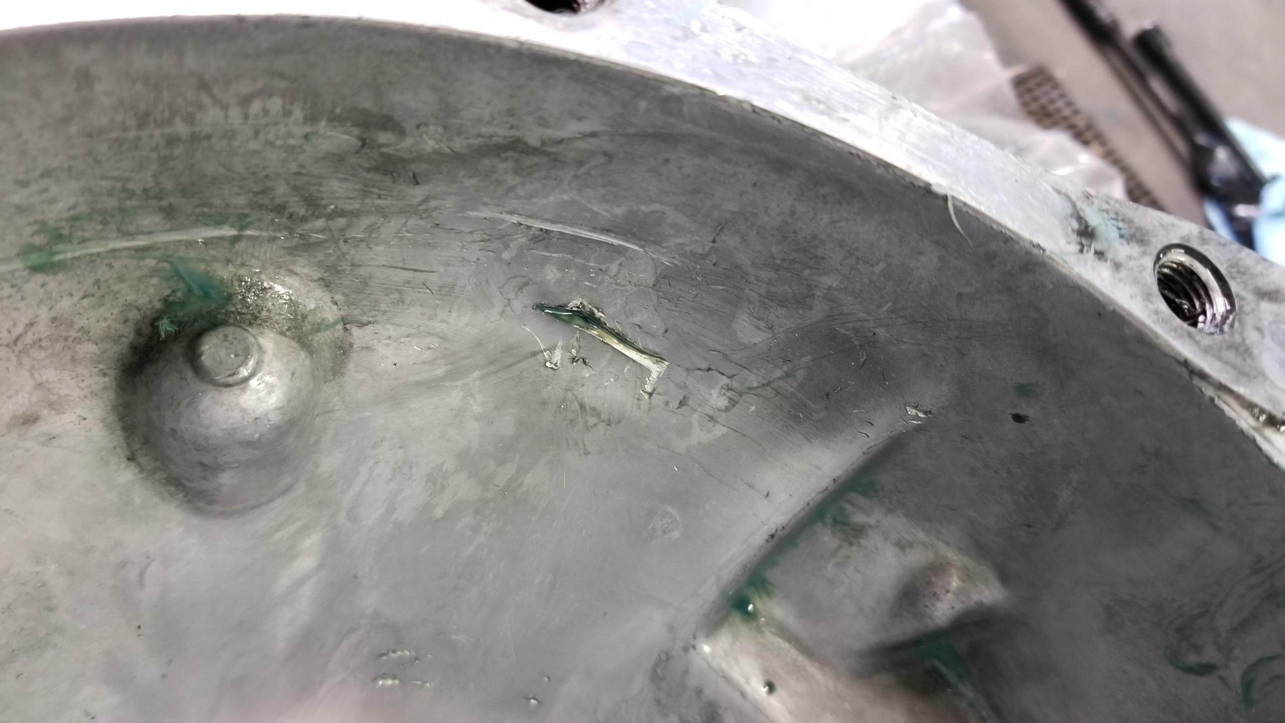
This was the second casualty, a bit under where the diff sits. Again, some filing down to make sure the burrs don't break off or hit something and I think this should be fine.
1kpu948.jpg


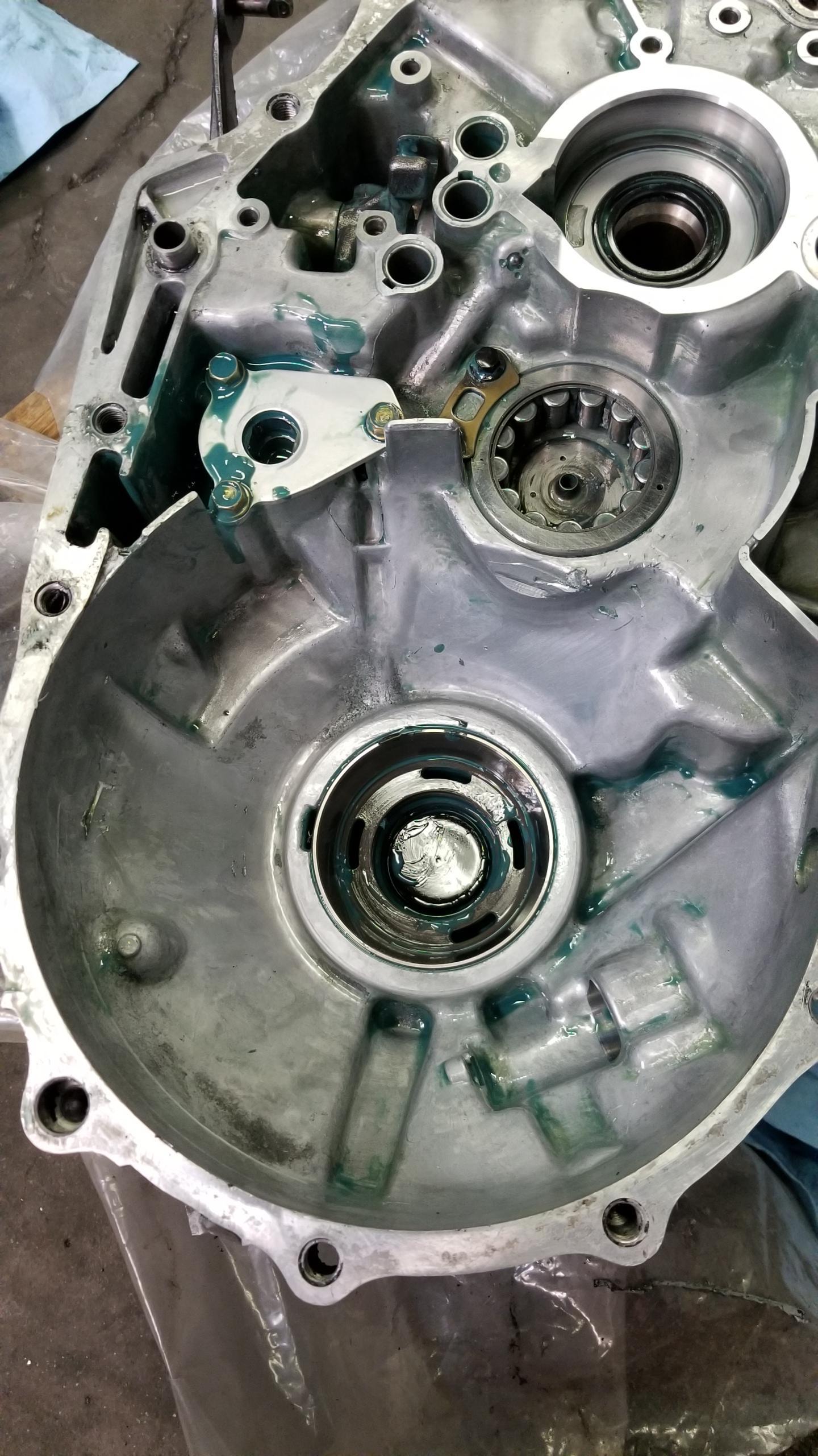
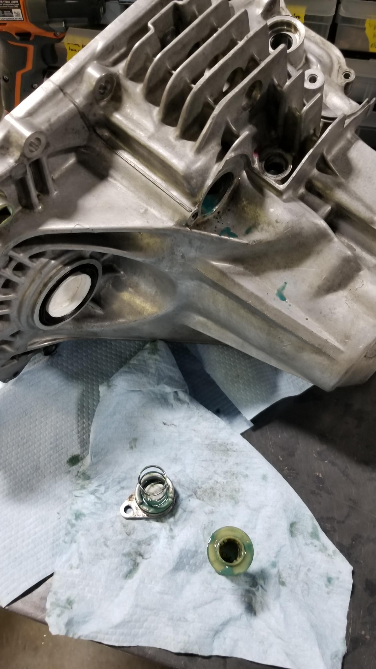
Here's the overall lower case. You can see the two spots in the pics above, there are a few little nicks in some places but seemingly nothing too bad. So far it seems like the shard made a few revolutions around the differential before the magnet trapped it, which makes sense to me due to the layout of the gears and magnet.
iFjruvv.jpg


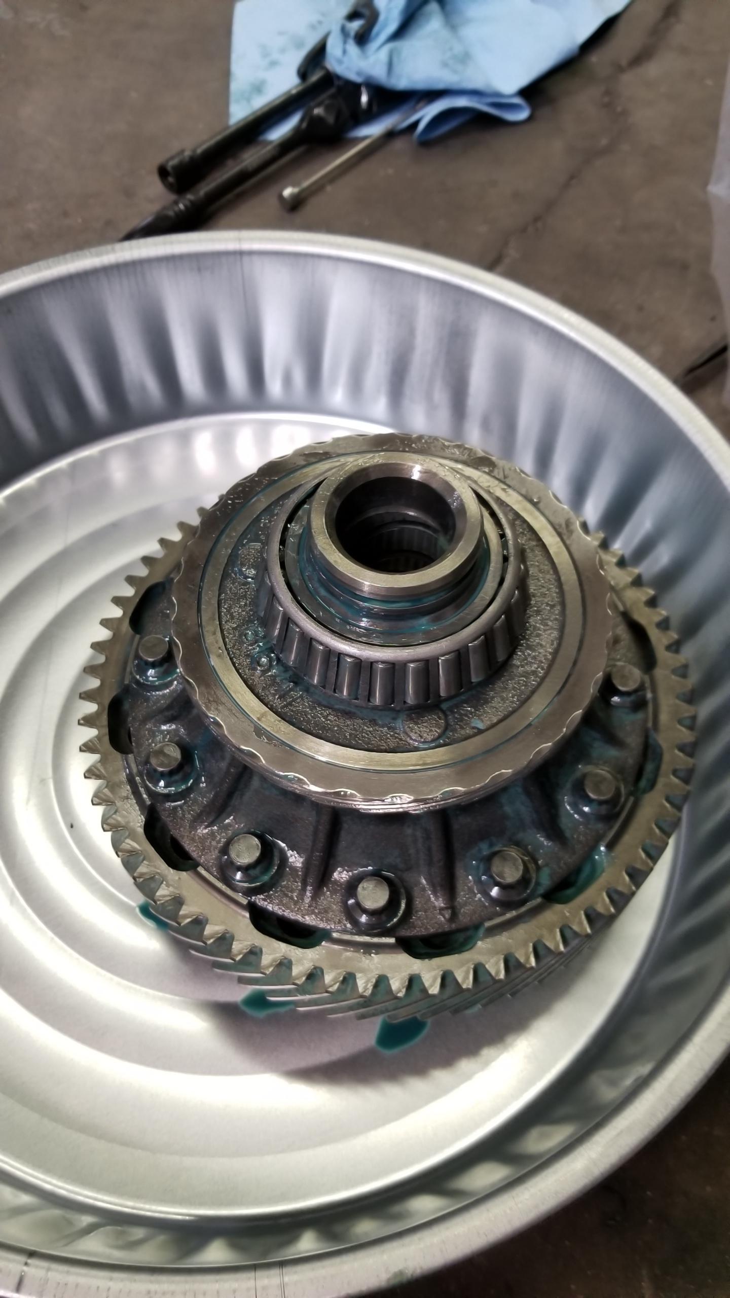
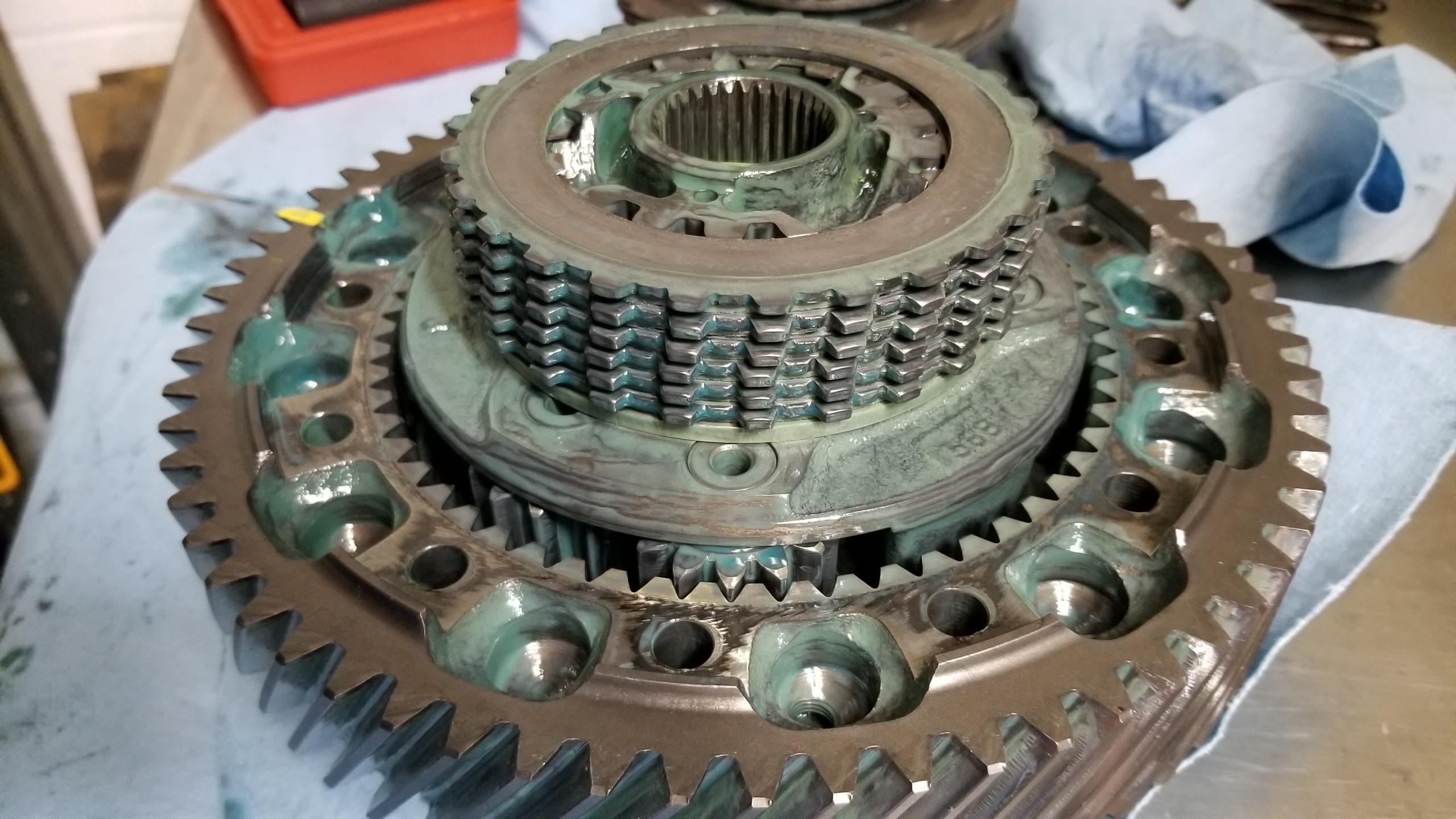
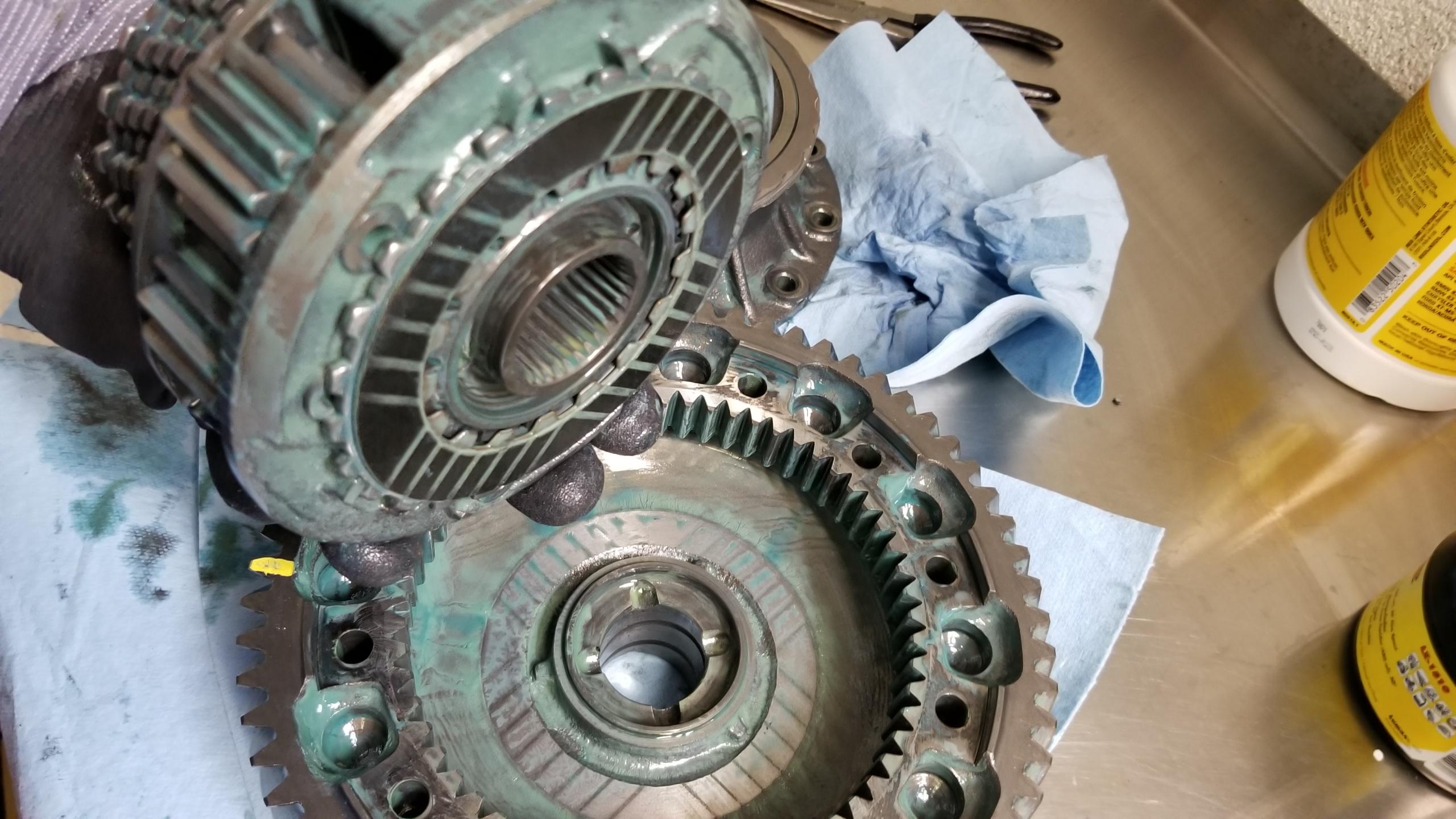
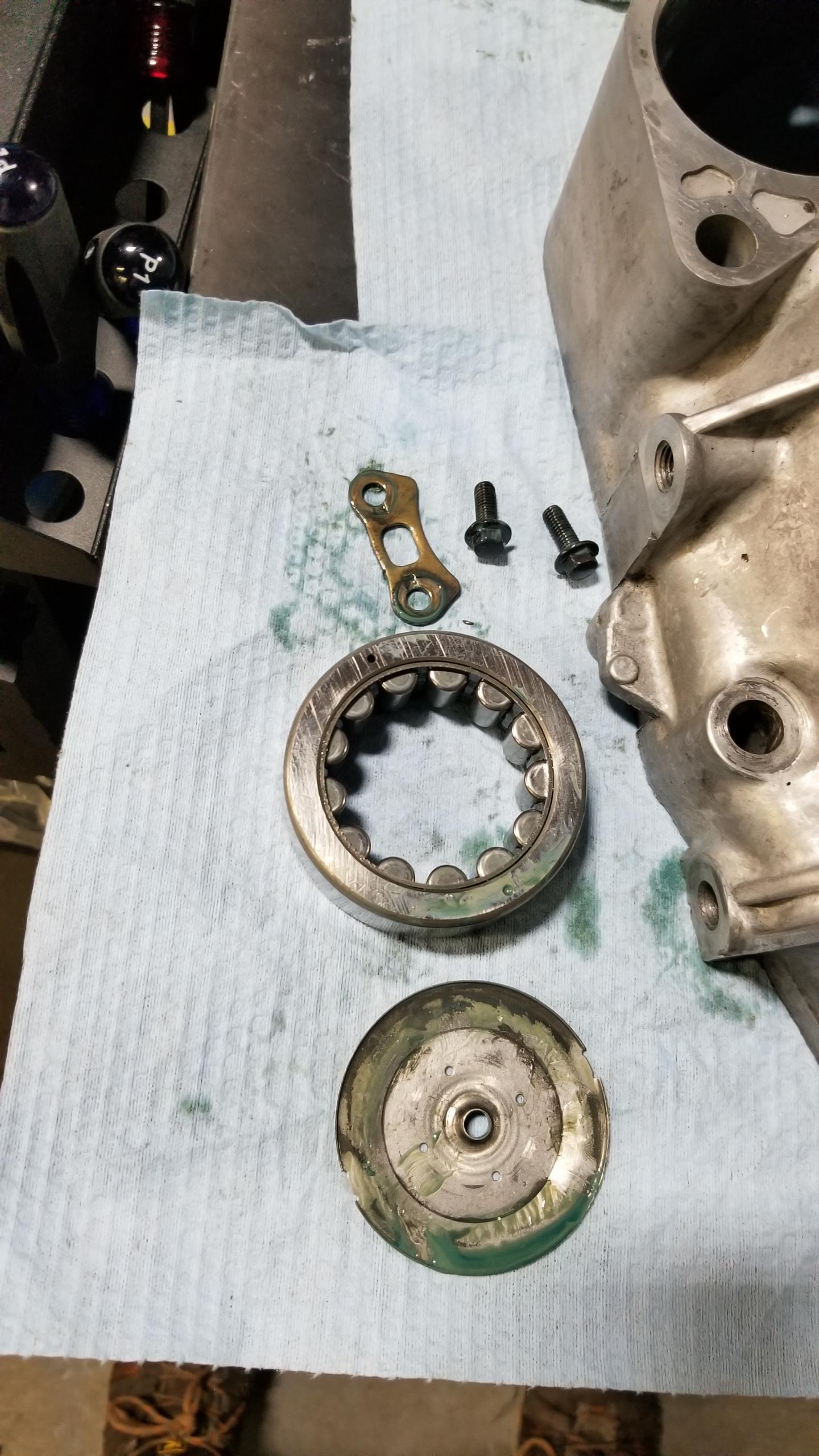
And the differential lifted out of its home. It is very heavy and pointy. Fortunately, after a few minutes inspecting, I don't see any obvious damage from the pinion shard, but I will be replacing the ring gear with the 4.23 version anyways so it wouldn't have mattered.
nLYHRiS.jpg


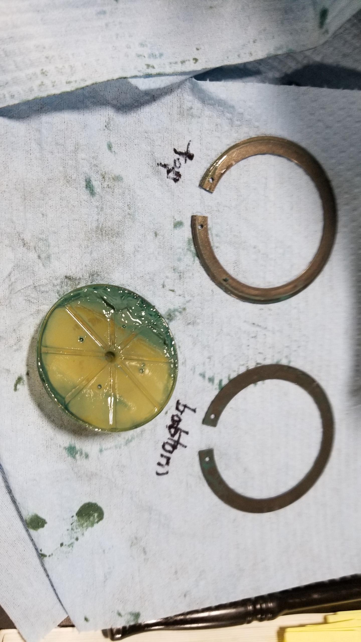
After zipping off the bolts in stages in a cross pattern with a 10mm 12pt socket, finally exposed the greasy internals. It appears to me as if this differential is the 90-94 torque control version and not the 95-96 updated torque reactive differential like I thought it would be due to the missing thrust needle washers and the presence of the spring retaining clip on the hat I removed. I posted a thread in the DIY forum just to make sure that's actually true.

If this is the early diff like I think it is, then I'm in luck because this one should be compatible with the 4.23 ring gear and I don't have to wait another few weeks to source the right diff. That would be a big holdup to this project so at least this seems to me like good news.
9Hv6Zxc.jpg


Underside of the planetary gearset/carrier if you were curious. I will be measuring the clutch pack thickness soon to see if it needs replacing but didn't get to it yet. There's some metallic clutch dust in suspension so it's been through some prior driving for sure.
BFJ8l0T.jpg


That's where I left off for the (late) night. I covered up everything with plastic to protect the pieces from airborne contaminants, which for now isn't a huge deal but will be once I get to full disassembly, cleaning, and reassembly, where the only thing I want inside the case once I seal it up is Honda parts and new oil. This weekend I will have plenty more time to dig in and make more progress. I anticipate this will probably take me 2-3 more weeks since I might end up needing to order other worn parts like gears, sleeves/hubs, and shims that weren't on my original parts list (and would certainly not have been provided by any other pre-made rebuild "kit").

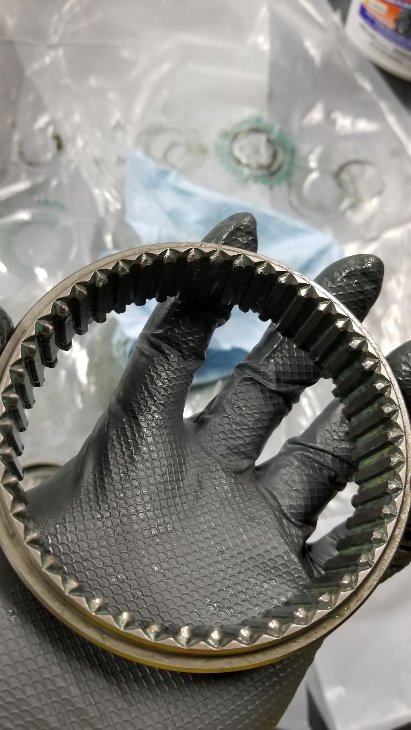
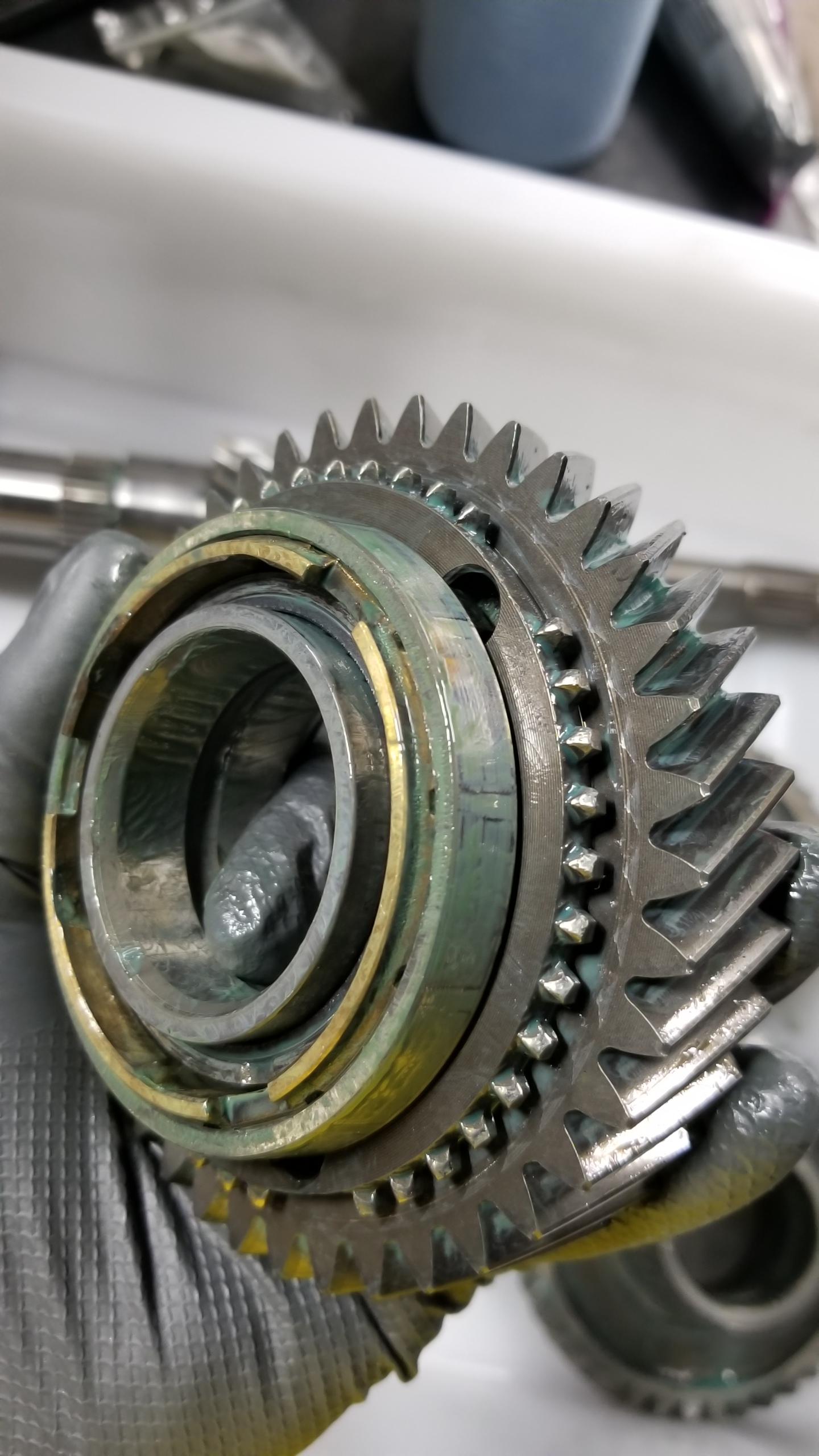
There was no noticeable wear on the outer gear mesh teeth but there was some visible on the synchro-gear mating teeth like on the 2nd countershaft gear (i.e. likely from hard 1-2 upshifts), so I'll have to weigh my options when I get to that stage. That particular gear happens to be discontinued (of course) so it probably would have to be sourced internationally, which would really suck because international shipping to/from the US is an absolute mess right now. If the worn gear is part of the JDM gearset it probably won't get replaced unless it's really bad since most of those are on a very long back-order. It seems to me like there are a few people looking for JDM gearsets now that are running into this issue, so I hope we're not at the stage where those parts are being discontinued altogether.

Though my original countershaft is only good as a lampshade holder or heavy blowgun, I'm still fortunate because I was planning on replacing it anyways and I have the 4.23 countershaft on hand, so I guess this means I'm doing the 4.23 conversion whether or not I can get it to work with the EPS system. If the damage was on the mainshaft or other component, I would be out another few hundred+ dollars and probably several weeks/months of time waiting for new parts :redface:. I still think this project will go well, I will find out more and post updates on the gear stack assy/disassy after this weekend.
 
I have a very similar creaking noise you yours. Mine is from the rear and I'm 99% sure is down to the lower rear ball joint. I can feel the vibration through the joint if I simulate the suspension loading and unloading slightly.
I have the replacement ball joint but not the time to install at the moment...


Still trying to figure out this very annoying creaking noise in my front end. I posted a thread in the FB group about it just now (https://www.facebook.com/groups/799...9&notif_t=feedback_reaction_generic&ref=notif)

I spent a while under the car prying and wiggling various suspension bits, mostly focusing on the front right since that's where most of the creaking seems to come from. The only obvious thing I could find was the right outer tie rod was pretty loose so I went about replacing it. Initially I ordered Moog replacement parts, but I didn't do enough research and found out later their outer tie rods don't fit my NSX. I had to wait for the twice as expensive OEM parts to arrive from the dealer since there doesn't seem to be any aftermarket options available.

I got the OEMTools brand separator pictured below instead of the Honda tool. This one doesn't have a side to side adjustment screw, but with the setup shown below the tie rod popped off in 2 seconds with an impact gun. I considered myself lucky since I've heard these can get really welded in place or the knuckle bushing will come out with the rod and have to be pulled off.
kpRbg1k.jpg


OEM rod end on the left, Moog on the right. At first glance they appear the same, but the male threaded end on the Moog part is too large to fit inside the steering knuckle bushing so it's useless. Unfortunately that seems to be true for the several remaining aftermarket brands as well.

You probably can't tell from the pic, but the threads on the old rod were pretty much flattened completely at some point in the past. I tried to reuse the old end before the new part came in, but the castle nut just spun and was only being held on by the cotter pin. I obviously wasn't going to rely on the cotter pin to keep my car from becoming Lightning McQueen so I had to mothball the car again.
3tRa3hw.jpg


Few days later, the OEM part came in. Apparently the left front outer tie rod is on backorder. Fortunately the one I needed came in.
SCQo4bF.jpg


And installed. I counted 17 turns to take off the old rod and put on the new one the same way. I'm sure my alignment overall is all over the place, but I have an alignment coming up soon after my trans swap. At the moment I'm not exactly doing performance driving with my Chinese all-seasons. I also didn't notice that $80+ doesn't get you a new cotter pin or castle nut, so I had to re-use the old ones. Not perfect but doesn't really bother me.
KqE9dcH.jpg


Everything was going swimmingly until I went to replace the sway bar link while I was in there. As you can see, the nut seized completely on the end of the upper stud during removal, and no amount wrenching would unstick it. My options then were to heat up the nut a ton and hope it broke loose or cut off the stud. I chose door #2 and used my Dremel to cut the stud at the base. It was tight quarters but I was able to make enough progress to snap the nut off after a few minutes, so it turned out okay.

The top is the Moog replacement part. This one fits fine, but the nuts are very tiring to tighten up without a ratcheting 17mm wrench, I only had up to 15mm.
aSKhpPE.jpg


Installed after some consternation. Unfortunately, neither this nor the new tie rod affected my creaking noise whatsoever, but I suppose having the new tie rod actually bolted to the car as opposed to the old one being held on by the cotter pin is a welcome improvement.
Lcymo5O.jpg


So, some new parts put on but I'm still dealing with this very annoying and loud creaking & popping. Here's a direct link to a vid I took of the noise (https://www.youtube.com/watch?v=W5m...MGMguxX-JY81eCqx3BUxMpuSIusAPR4kVmhUXfIHswZtg).
It definitely sounds like a metal or rubber tightly rubbing against something. It seemed to start after I sprayed some suspension bolts with penetrating oil a few weeks ago, but I haven't been able to pinpoint where exactly the sound is coming from.
 
@sca037, I think I might have found the cause of your LSD "popping" noise :biggrin:


I think you might just be onto something there!
Strange that "popping" sound was only really apparent when pushing it backwards (no load) in the garage, but that car has a loud exhaust so???
I'm not sure if it's correct, but my theory was that the transmission loved that Redline Lightweight Shockproof oil.......but the Differential, not so much.

Keep the Covid-19 quarantine updates coming :cool:
 
I have a very similar creaking noise you yours. Mine is from the rear and I'm 99% sure is down to the lower rear ball joint. I can feel the vibration through the joint if I simulate the suspension loading and unloading slightly.
I have the replacement ball joint but not the time to install at the moment...

Thank you for the suggestion! I will get back on the lift and use a jack to load up the wheel and see what I can feel. I assume you got the Rare Parts balls from this thread? (http://www.nsxprime.com/forum/showt...-joint-replacement-Whats-the-real-story/page3). Seems like the other options are an install by Carbon6 for $500+ a side plus install (http://www.carbon6composites.com/product_info.php/cPath/21/products_id/31) or ASM for similar (http://as-motorsport.com/site/en/ca...-22/front-knuckle-upper-lower-balljoint-p-249).

If I do find out it's the ball joints, I might try spraying them with silicone or something before trying to replace to kick the ball down the road a bit. I have a feeling that some bit of penetrating oil might have made it into the boot and caused the creaking, maybe I could just do the boot replacement and re-grease. It would be nice if they were actually serviceable, taking out the knuckle and dropping another $500 wasn't on my short list of things to do.

@sca037, I think I might have found the cause of your LSD "popping" noise :biggrin:


I think you might just be onto something there!
Strange that "popping" sound was only really apparent when pushing it backwards (no load) in the garage, but that car has a loud exhaust so???
I'm not sure if it's correct, but my theory was that the transmission loved that Redline Lightweight Shockproof oil.......but the Differential, not so much.

Keep the Covid-19 quarantine updates coming :cool:

I think it might be that there was too much other noise when the car was on to notice the popping, pushing it around in neutral with the engine off probably allowed you to hear the popping when the pinion would suddenly skip a tooth on the diff and hit the next tooth harder.
 
Wow, good thing you took apart the transmission before bolting it to the car.
Not sure who thought of the idea of adding a magnet to the transmission case, but they should get an award. :)
 
I did not buy the Rare Parts ball joint, I used the part numbers from that thread along with the Rock Auto website to identify a part manufacturer that I could source in the UK. Was only about GBP15.
I'm hoping I can press it out in situ.

I tried to re-lubricate it with fresh grease but it was futile.

Got it. I was looking into that here (https://www.rockauto.com/en/moreinfo.php?pk=493152&jsn=3) for some options. It is cheap enough that I wouldn't mind trying that out first, but I'd be concerned about fitment especially after my aftermarket tie rod end didn't fit right and I can't find a part number that cross references with the NSX.

My plan is to spend some quality time with the knuckle ball joints today to see if they are the problem (I'm 90% sure now). If so, I plan on using a needle fitting on a grease gun to inject fresh stuff and seal up the hole I make. If it works then I saved myself a lot of trouble and money (at least temporarily), if it doesn't then I would be replacing them anyways. I have the feeling that the penetrating oil I sprayed on the castle nut might have seeped into the boot in between the ball stud and housing and displaced the grease, which might be why the creaking sounds more like tight metal-metal contact. I'll update this with my actual findings.

Wow, good thing you took apart the transmission before bolting it to the car.
Not sure who thought of the idea of adding a magnet to the transmission case, but they should get an award. :)

Right? At least the tooth was magnetic and not a piece of brass or aluminum. I haven't pulled the strainer yet but that might have more surprises.
 
Last edited:
After messing around under the car again for another hour or two, I've finally isolated the issue causing the creaking noise.

My camber adjustment bolts on the front were not tight enough and allowing the control arm bushings to build up tension under compression, which then let go at a certain point and rubbed the bushing against the metal flange.

I took a video to illustrate this. You can actually see the bushing loading up and then releasing when I jack the tire up and down again. It took a while to see this happening under the car since I needed to jack the wheels up over and over again and the sound was resonating through the steering rack and lower control arm, so it made me look at a few incorrect places.

I tightened both camber locknuts to 100 lb-ft (+10 vs. factory spec) and the one making the most noise was already 10-20 lb-ft too loose, which let the control arm bushing slip & creak more. I think when I sprayed penetrating oil on the bolts in preparation for removal, the oil got in-between the bushing and bolt flange and "unfroze" them enough for them to start slipping past each other like a bad clutch.

Since tightening them I have no more noise whatsoever, so I avoided replacing more complicated or expensive parts for now :biggrin:.

https://www.youtube.com/watch?v=_WmX-7s_qPA
 
Last edited:
Trans Rebuild pt2

Really great write ups! They're super helpful, especially with the accompanying detailed photos.

Appreciate it! It gives me more motivation to get things done when it's not just me re-reading my own posts.

Here's a little update with the transmission rebuild. My goal for this afternoon was to fully disassemble the shafts and inspect everything closely to see what else needed replacing. Suffice to say, just like any other project, the budget gets thrown out the window. I should start factoring in contingency money like a real project manager would do.

This is my nut choocher for the countershaft. I had bought an expensive 40mm impact socket but the socket was slightly too small to fit over either the old or new locknut, so I guess the tolerances for such a big socket aren't quite there...Instead, I got a cheaper 1-5/8" 12pt socket from Autozone and that fit just fine. I can probably use my new 40mm as a press tool or for throwing at my enemies if it comes to that.
WIDmBv3.jpg


Nut un-staked with some punches and a hammer (annoying) and removed with the impact. It is reverse-threaded, so I set the impact to "tighten" and after a few seconds of ugga-dugga-ing the nut came loose pretty easily. I just held the shaft in my arms and let the impact do the work. I'll have to use a vice to tighten the new locknut but it will be "interesting" to see how tight I'm willing to make the vice to get back to 116 lb-ft since the original countershaft pinion gear tooth broke off somehow. I doubt it was during the last rebuild but who knows. It has to be tightened to 116, buzzed off again, and then re-tightened to 116 again before staking since I guess the initial tightening helps compress the rest of the parts or relax the nut threads so that it doesn't lose tension over time?
LP1LdIx.jpg


Once the nut came off, the two top bearings actually came off by hand without a puller/press, so that was a nice time saver. Unlike the mainshaft, the rest of it needs one of the two tools to take off the press-fit parts.

The shop I'm using has a sufficient bottle jack press, which makes the disassembly fairly straightforward. I used the old locknut as a protector for the shaft itself kind of like using the castle nut on a suspension part when pressing a ball joint out, but I wasn't using this countershaft anyways so it's mostly just practice for reassembly. It would be pretty unpleasant to use a gear puller for this stage, especially since I'm very sensitive to causing damage to the parts, so the less I handle them the better.

I followed the FSM for the 5th & 4th gears shown here, pressing the shaft out from the middle. Obviously I went very slow to make sure the press was going smoothly without binding, and held the shaft securely as it fell out of the press, dropping or nicking anything here would really suck.

Unfortunately, the press blocks were too thick to fit in-between the 1/2 slider and 2nd gear, meaning I couldn't follow the FSM for removing just the 3rd/2nd gears next. After a lot of failed attempts with other press bases, I just supported the shaft from the bottom of the reverse gear and pressed out everything at once (3rd, 2nd, 1/2 hub, 1st, and reverse gears). You could probably do this for the whole shaft but I'd prefer to do it in stages to reduce the total pressing force on the top of the shaft and gears since the shaft is hollow and I'd rather not pancake it. The parts were not on super tight so the press make quick work of removal.

I'll get some thinner shop press bed plates for the relatively low-pressure reassembly to make my life a bit easier.
ln0wnbx.jpg


Countershaft disassembled and parts laid out from left to right. Essentially, most of this will be replaced........the only things I'm planning on keeping are the 4th/3rd/1st/reverse gears and the spacer collar. Some explanation of why I seem to be obsessed with destroying my budget below.
VFOBqEI.jpg


I hadn't ordered any of the sliders & hubs in my original parts list since I hoped I could save the extra few hundred and reuse the old ones. The hubs looked fine, but the slider teeth were not fine. Pic is of the 2nd gear side of the 1/2 slider. This one is unsurprisingly beat on a lot during spirited driving and pretty much every tooth was rounded or otherwise deformed. The 5th gear slider was the same, and the 3/4 slider but a bit less so than the 1/2 or 5th sliders.

Since the slider & hub needs to be replaced (and are sold) as a set, that's another 3 part numbers added to the list. Could I reuse them? Sure, but my philosophy with this project is to maximize the life of the transmission for long term usage and potential tracking in the future, so I want to be meticulous with my work. These worn sliders will make shifting sloppier and probably wear out my new blocking rings and gear teeth faster, so I'll have to take the hit to my budget on the chin. Hopefully my 5+ year future self will thank my poorer current self for doing the needful, as they say.
gZXNjkp.jpg


Similarly, my 2nd countershaft gear dog teeth (or engagement teeth? What jargon to use?) were pretty worn down. The main teeth all look good, but these engagement teeth will make shifting more difficult and wear down other parts faster. This is part of the JDM short gear set, but I'm hoping Amayama can come through in the clutch again and ship me a new gear. The same was true for every gear with engagement teeth except for the countershaft 1st gear and reverse gear.

vX1TGvv.jpg


The only one I didn't mention was the mainshaft 4th gear, which I would consider replacing if it weren't practically discontinued. Others have waited months to a year to receive one, so I have to reuse this one. It's not worn too badly but I will carefully de-burr the engagement teeth to reduce the chances of the slider being caught on a protrusion.
2vfo1mb.jpg


The JDM mainshaft's input side bearing was a super tight press fit unlike the rest of the bits, so that went in the shop press as well. I pressed against part of the outer race due to the lip on the shaft blocking the inner race, which would be a big no-no but the bearing will be replaced so no matter. I'm ordering a new pilot bearing (was originally going to get with the new clutch kit in the future) so that I can test the fit on the input shaft, and the shaft will be getting a thorough cleaning since it has plenty of schmoo built up inside.
of09pCf.jpg


Basically, I ordered these parts, my "wear" ratings in parentheses:
-mainshaft 5th gear (3.5/10, engagement teeth worn beyond what I want to reuse, maybe someone skip-shifted into this a lot?)
-countershaft 5th gear (6/10, one main tooth is slightly chipped so to be safe I will replace it)
-mainshaft JDM 3rd gear (6/10, engagement teeth somewhat worn)
-countershaft JDM 2nd gear (5/10, engagement teeth worn)
-5th gear slider & hub - engagement teeth worn nearly as bad as 2nd
-3/4 gear slider & hub - not as bad, but with the old 4th gear I figure a new slider will help prolong service life
-1/2 gear slider & hub - 1st side not too bad, 2nd is bad so this is due for replacing
-a differential spring plate for the Type-R conversion since it's backordered in Japan and I forgot to order it from Acura

5th main gear (shared between both US/JP 5-speeds) is discontinued and Acura cancelled my order, but I found one tuning shop that happened to have one in stock. Hopefully you guys are treating your cruising gear gently and not skip shifting into it, I've read a few different threads about how this gear is especially susceptible to wear especially with the old spec of thinner shift fork. I'm having to replace both main & counter 5th gears and the slider, and the main gear seems to be out of production in most places so you might have trouble getting a new one if you start having issues.

These aren't traditionally replaced components, but I guess that's what inspecting is for. Now it's a waiting game to see when I can get everything in. I have an order placed with my pals Amayama again so hopefully they come through with DHL Express and help me get this project back on track soon. As an aside, if you're thinking about shipping anything internationally, for the love of god, please don't use USPS at the moment. You will almost certainly be waiting weeks or months without any updates on your expensive packages. Ask me how I know.

I will probably spend some more time this weekend fully disassembling both trans cases for cleaning & reassembling whatever I can to prepare for the next half of the rebuild. I'm saving the cleaning of the internals for the last minute so I reduce the chance of contamination before reassembly and to keep a layer of oil on the parts to prevent rust. Also waiting on a depth micrometer so I can measure my differential clutch pack & washer thickness to make sure that's within spec before I reassemble the diff again and check bearing preload, I'm sure it will be challenging to change the diff bearings and races based on Motormouth's experience. Having to replace the clutch pack as well would suck since that's another couple hundred sacrificed for the greater good (of my car :cool:).
 
Trans Rebuild pt3

A bit more progress has been made, namely stripping down both case halves to prep for putting in all the new parts. More pics since I have nothing else do to tonight.

Here's the new mainshaft 5th gear. I'll be nice and say it's from Flatiron Tuning, they have an odd assortment of NSX transmission parts that seems to be dwindling down so hopefully I don't need any other discontinued parts :ghost:. I also got an open box but complete set of Goodridge braided brake lines from them a while ago for a really good price, which will be put on during a complete brake refresh due sometime this year.
WpMutJ0.jpg


Also got a new depth micrometer gauge specifically for measuring the differential clutch pack to ring gear clearance per the manual. Not something every rebuilder would do during this project, but my philosophy is to be as thorough as reasonably possible so this will help me tell how worn my clutch pack is. It goes without saying that having to replace it would be an undesirable punch in the wallet.

This is the inside of the transmission side case with the snap ring. Some little nicks on the casing I deburred before cleaning it out. The left-hand big hole holds the mainshaft thrust shim(s) and oil guide plate, the right-hand hole is where the snap ring sits. I removed everything but the snap ring, as others have said it seems annoying or potentially damaging to the case to try and remove it unnecessarily; I might try to mess with it a bit to see if my lock or snap ring pliers will take it out easily enough for a peace-of-mind replacement.
xS3mDvz.jpg


Mainshaft thrust shim(s) removed. Mine turned out to have two shims, top measured 0.99mm (or 1.00mm, shim K) and bottom was 0.69mm (or 0.7mm, shim E), dunno if my caliper was measuring low or they were actually 0.01mm off from factory new. The service manual says no more than 2 shims is fine, so mine totals to 1.70mm as previously installed for the mainshaft thrust clearance. My spring washer was 0.83mm thick (or would it be 0.84mm actually?....), so I'll combine all these numbers when I reassemble the mainshaft and test the new thrust clearance. Hopefully since I didn't change the mainshaft itself it'll be within spec with the same shims, if not I'll have to order more shims from Acura. I have a new spring washer but probably not necessary to use and would likely change my thrust clearance.

The oil guide plate had some viscous schmoo behind it so it will be good to clean off. Eventually might start reducing oil flow to (or from?) the shaft which isn't ideal.
v4wXs3H.jpg


This is where the shift lever was attached. One spring washer to replace along with the O-ring sealing to the outside world.
1VaVSQq.jpg


Below is the fluid strainer and cover removed. This is serviceable while the trans is on the car but it's more annoying to get the leverage needed to remove the cover and pop the strainer & spring out in that situation since I've heard the cover can get corroded and seize onto the casing. This one came off with some prying, and I'll put some silicone grease under the reinstalled cover for corrosion resistance if I remember to ;).
9BJL2SS.jpg


Inside of the strainer. It looked surprisingly clean which is a welcome change. I have a new O-ring, spring, and strainer to install which is a bit overkill but they're cheap and I did the work already.
QQPHDWf.jpg


Time to push out the differential bearing race and oil guide plate. I had a 2" diameter PVC pipe from Home Depot I pre-bought to use as a press tool, but all it took to pop everything out was a light tap from behind, I could have probably pried the race out by hand with some patience since it was a fairly loose fit.
87V1KLF.jpg


Everything plopped out. Roller bearing race, 75mm washer, O-ring for the trans case side of things.
4IuIhZJ.jpg


This is my nice little Lisle seal remover tool. Much better leverage than a screwdriver, just have to be careful to hook against the inner part of the seal so as not to scratch the machined part of the case. I did marr the input shaft seal surface slightly with this but a touch of Hondabond should prevent any leaks, not that it would be likely to leak anyways unless you manage to gouge a line all the way through the sealing surface.
9pAWIrc.jpg


Cleaning takes a long time to get the insides to a mostly oil-free level. I mainly used a Brakleen-style degreaser (not the bottle in the pic) so it wouldn't leave behind contaminants. I also carefully deburred the scratches in the casing and wiped away the filings carefully without spreading them around. I used some new trans oil to coat the machined surfaces just so they wouldn't corrode before I reassembled everything. They're probably aluminum anyways but figured it couldn't hurt.

I still have to scrape away more at the sealing flanges around both cases, but I left that until later. I will be using some Scotchbrite pads to prevent marring or leaving bits of steel wool or something that could break off inside or rust. It'll probably take an hour or two of just focusing on the flanges to make sure they're as squeaky clean as possible, including all the bolt and dowel holes with bits of old sealant in them.
IKrmSoS.jpg


Onto the clutch-side housing with more parts to remove. This is the countershaft needle bearing with the retaining plate already removed. The manual says to using a Honda discontinued unicorn tool to remove the bearing from the case, I tried a rental pilot bearing puller but realized the screw in the middle would crush the oil guide plate nipple so that was abandoned. For some reason I tried removing it just by pulling on it by hand, and whaddya know, it came out just with my finger strength since it was a fairly loose fit. That's a time saver.
6suhWVR.jpg


Disassembled state of above pic. The two bolts that hold the retaining plate are both staked to the plate, so they're technically supposed to be replaced during reassembly. I have two new ones to put in.
XH5dlhy.jpg


On the other side of the case, I went about removing the release bearing guide. You can see the gouges on the old guide, in Kaz's opinion this is a "must replace" item and this one is worn enough for me to replace it. From Japan it's $80 so not the cheapest ever but I guess in a cosmic sense it's peanuts to the overall cost. It can be replaced easily during a normal clutch job if needed. The ring plate on the right is only present on later transmissions, not sure if it's for extra protection or something but good to have I suppose.

In the background is the blanking plug for the extra speed sensor. I believe I can steal one of the sensors off of my auto trans once removed and put it in that hole to plug up to the same connector as the A/T and have the EPS system work, though LarryB says he needed a spacer washer to prevent the sensor from hitting the differential ring gear inside. The sensor picks up the ring gear speed and transmits that for the EPS brain, and I've been told by Science of Speed that the sensor signal resulting from the new 4.23 ring gear will not work with the EPS brain and make the whole thing a paperweight, but both LarryB and Brian from Speedhunters (who both have firsthand experience with this situation) say that their EPS works just fine with the 4.23 ring gear. I think SoS is right that the '95+ EPS computers (or is it '97+? Still would need the 90-94 torque control diff) won't work with the 4.23 gear, but based on the above info I believe it will still work with the early 90-94 EPS brains. This is still quite a rare situation to be in since only the 90-94 automatic cars had EPS in the first place, so really only something you'd run into if you were swapping to a 4.23 manual trans and keeping the EPS, which I am.
EDIT: I should add that I'll likely need a spacer/washer to put on the new speed sensor, since others have experienced premature sensor failure trying this because the 4.23 ring gear is larger in diameter and hits the sensor head just enough to chip away at it and eventually break it. Wasn't a problem with the NSX-R since they had no EPS so it wasn't a design case.
CcmbRAm.jpg


While I had the clutch case turned around, the other diff bearing race and company decided to slide out by itself onto the bench, and the oil guide ring plopped out with some gentle persuasion. I suppose they're also a loose press fit, but it saves me the effort of pressing them out. I think this might be annoying during case reassembly since I'll probably have to put the race on the bearing itself before gluing the cases together so that the race doesn't slip out during the process.
NsQ8uh4.jpg


Clutch case diff bearing race, 90mm washer, oil guide plate, and O-ring.
hS4O8qv.jpg


Back inside, the oil pump rotors. I measured the clearances according to the manual and they were good. It seems like the inner and outer rotors have little dots on them so I'll keep those in the same position during reassembly. Everything pulls out by hand here. The relief valve spring has another steel ball behind it that you shouldn't lose.
NKmS0qs.jpg


This is the spring washer that sits against the input shaft side and affects the thrust clearance. I have a replacement but probably more trouble than it's worth to replace.
tSEcjg5.jpg


And the clutch case after some light deburring and cleaning of the insides. I'm still cleaning out the green goo from the crevices, the more clean the better so that less of it drips out to potentially ruin my Hondabond seal.
tJRGygo.jpg


Another long while cleaning off the clutch side of the casing. Lots of degreaser, brass brushing, and spraying off. I tried to get into all the little crevices but it's like it was designed to be impossible to clean. This is still 90% better than before, and the less dirt the better so the release bearing grease traps less crud. I might again for a better cleaning soon.
8bxuq2w.jpg


That's it until I get my overnight parts from Japan (as if, likely 1-2 weeks from now). Once I get those sleeves & gears, I'll begin reassembly of everything and post the last trans rebuild updates here. Hoping that goes as smoothly as disassembly did, though I think the diff preload/breakaway torque and bearing replacements will be fairly annoying. I might get a machine shop to do that if my attempts are fruitless. I'm sure the reassembly will take longer since I have to make sure everything goes back perfectly, but I took my time and labeled/took pics/videos of everything so I should have set myself up for success.

vaRhIRV.jpg


This week in sports, Pride has just restocked their V2 headers after quite a while, which are supposed to be compatible with automatics (most aftermarket headers I've seen are M/T only). Aaaaaaand I ended up ordering a pair...I always had my eye on their stuff, but my plan was to tackle the entire exhaust and do the V2 exhaust, test pipes, and these headers all at once after the transmission swap so that I wouldn't have to mess around with the rusty lumps that are my exhaust studs/nuts and just pull the whole thing down as one piece.

I was planning on replacing my rear manifold anyways since I still have the stupid O2 sensor threads broken off inside, but I haven't been able to source a used boat anchor yet. Since these V2's just became available, I figured I'd just get them now so that I wouldn't have to do the rear header job again. I will almost certainly have to cut off my cat nuts/studs and replace them which is a pain in the ass, but should be manageable and I'm sick of the yellow CEL for a missing O2 sensor (plus my gas mileage sucks). Plus, it gives me an excuse to drop the oil pan (again...) and re-seal it according to the new manual, which calls for Hondabond in 4 places. It seems my new pan & gasket STILL leaks, so I can fix that and also get the SoS pan baffles I ordered a while ago installed in my new pan, killing many figurative birds with one figuratively expensive stone.

I'm looking into getting the headers ceramic coated as well since it seems like good insurance for heat management and longevity. It would've been nice to do the entire exhaust at once, but I put "flexibility" as a strength on my resume so I must be true to myself.

Here's a car pic from today since it's probably pretty dull to look at so many greyscale pics in a row. Doesn't look like much has changed, but beauty is more than skin-deep :smile-freehand:. I had a kid and another guy driving past basically scream (in a good way) as I drove by so I must've done something right.
mCPO7hW.jpg
 
Last edited:
Tyler- amazing work so far! It's funny- we're pretty much building the same car lol. I just ordered my Pride V2 headers yesterday. ;) I would advise against using the scotchbrite pad to clean the case surface. The pad contains thousands of micro-abrasive particles (likely aluminum oxide, e.g. sandpaper!) and it's almost impossible to keep them from getting into the machined areas of the transmission cases. If you do use it, make sure to thoroughly clean and clean again the cases. My tried and true method is to use lots of remover to soak the hardened Hondabond and than carefully scrape it away. [MENTION=33247]MotorMouth93[/MENTION] also had good results with a brass wire brush.

Have you though about pressure washing the inside of the clutch case? It's aluminum, so there should be no concern about rust. It would get all of those nooks perfectly clean...
 
Back
Top