• Protip: Profile posts are public! Use Conversations to message other members privately. Everyone can see the content of a profile post.

Bose Amplifier Rebuild DIY Video

Joined
30 October 2016
Messages
1,122
Location
Austin, TX
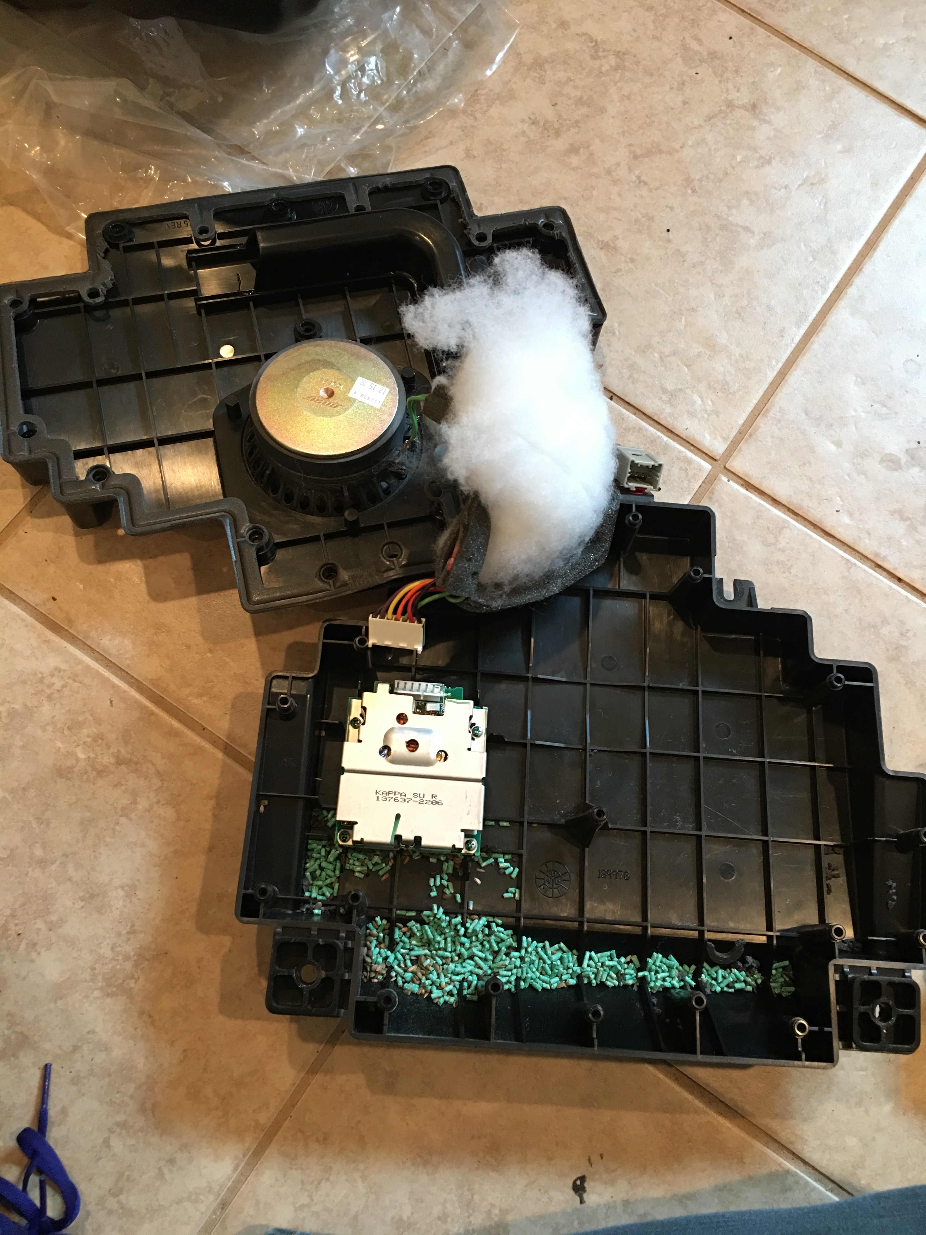
I'm in the process of rebuilding my OEM Bose amplifiers, would there be any interest in a DIY how-to video and parts list? If you have some basic soldering skills it's pretty straightforward and the parts themselves are less than $30 to do all 3 amplifiers, which is far cheaper than either replacing the whole speaker boxes or paying someone to rebuild them for you. The stock Bose system is actually decent when the amps work right.

There are a few different revisions of the amplifier boards and the capacitors are slightly different between those versions, so right now, the parts list is only accurate if your board looks like the photos below. If anyone has the different style amplifier boards please let me know so I can get the info together for them as well.

Tools Needed
If you don't have access to most of this stuff already this project probably isn't for you, while not difficult, this is not a good "babbys first soldering project". If you don't already have a soldering iron and know how to use it, turn back.

- Multimeter for checking your work.
- Soldering iron. (25W or less)
- Rosin flux.
- Lead solder. (you can use lead free but it's much more difficult to work with)
- Desoldering braid or solder sucker, whichever works better for you.
- Fine needle nose pliers or tweezers.
- Tiny wire clippers or scissors.
- Flux remover.
- Conformal coating.

Parts List
Current as of 11/2017, parts will likely be unavailable in a few years and new ones will need to be selected.

Capacitor, 1uF, 50V
Door Board P/N: C16, C110, C130
Footwell Board P/N: C16, C120, C121, C130, C203
Suitable replacement: Rubycon 50YXJ1M5X11
https://www.digikey.com/product-detail/en/rubycon/50YXJ1M5X11/1189-1421-ND/3134377

Capacitor, 10uF, 35V
Door Board P/N: C31, C172, C183, C203
Footwell Board P/N: C31, C172, C183
Suitable replacement: Rubycon 50YXJ10M5X11
https://www.digikey.com/product-detail/en/rubycon/50YXJ10M5X11/1189-2322-ND/3562914

Capacitor, 47uF, 16V (same for door and footwell amps)
Board P/N: C7, C8
Suitable replacement: Rubycon 50YXJ47M6.3X11
https://www.digikey.com/product-detail/en/rubycon/50YXJ47M6.3X11/1189-2325-ND/3563118

Capacitor, 820uF, 16V (same for door and footwell amps)
Board P/N: C19, C25
Suitable replacement: Rubycon 16ZLQ820MEFC10X12.5
https://www.digikey.com/product-detail/en/rubycon/16ZLQ820MEFC10X12.5/1189-3630-ND/6049867

MOSFET (same for door and footwell amps)
Board P/N: Q1, Q2, Q3, Q4
Suitable replacement: IRFIZ24NPBF
https://www.digikey.com/product-detail/en/infineon-technologies/IRFIZ24NPBF/IRFIZ24NPBF-ND/811806

If you do all 3 (and you might as well do all 3 since parts are so cheap), I'd order 15x1uF, 15x10uF, 10x47uF, 10x820uF, and 15 MOSFETs. You want a few extras of each in case you ruin one or you get a bad part, the total should be under $30 shipped from Digikey, Mouser, etc. Also, the MOSFETs don't need to be replaced unless they have failed, but I went ahead and replaced mine anyways and added thermal transfer paste to help keep them a bit cooler.

Parts To Be Replaced

door_speaker_amp.jpg
footwell_speaker_amp.jpg
(Thanks to user BrianK for helping me figure out which capacitors go where on this board after I mixed them up by mistake.)

Video Tutorial
Raw footage has been recorded and I'm in the process of editing it.

Also many thanks to users Kaz-kzukNA1, BrianK, and Old Guy for contributing to information in this post.
 
Last edited:
You're the man! I've been trying to piece together the info needed to replace the components without having them in front of me, but it's been tricky. All the other threads I found suggested that two of the drive MOSFETs were different (P-channel, I assumed), but it sounds like they're all the same.

For reference, these are the threads I found with info on rebuilding the amp boards:
https://www.nsxprime.com/FAQ/DIY/bose_rr.htm
http://www.nsxprime.com/forum/showthread.php/38480-Driver-s-door-amplifier
 
Excellent information!

Are you planning for MOSFET replacement because you know or suspect that you have a MOSFET failure? The reason I ask is that unlike electrolytic capacitors which definitely age with time and temperature, the ageing rate in semiconductors is generally glacial (with notable exceptions in some earlier integrated circuits which had rather spectacular failure rates) and not likely a problem. If one or more of the MOSFETS has failed because of an associated capacitor failure, then absolutely plan for replacement. If not, they might be better left alone.

First tip is that the solder side of the circuit board will likely be covered with something called conformal coating which protects the solder from deterioration. When you attempt to desolder the components the conformal coating will get on the soldering iron tip, typically fouling it so that you don't get good tinning and heat flow and making the job harder than necessary. Try to remove the conformal coating just on the soldering pads that you are attempting to desolder. Some conformal coatings will dissolve when acetone is applied with a cotton swab. Some coating are harder and it may be necessary to carefully abrade the coating with something like a soft bristle brass wire brush (no steel bristles). If you have conformal coating remaining on the solder pads after removal of the parts it will make soldering of the new parts in place difficult.


Second tip. You specified a soldering iron. To be more specific it should be a 25 W or less soldering iron, preferably with a small chisel (not pointy) tip. People with Weller 125 W soldering guns should stay away. You specified desoldering braid which means that you have way more coordination and patience than I have, particularly when using a 25 W iron. I prefer a solder vac - much easier to use and good ones are fairly inexpensive. This one is really cheap; but, I can't advise on how good it is.

https://www.sparkfun.com/products/13203

The hot ticket (no pun intended) would be a hot air rework station if you can beg or borrow one from a friend who does electronics type stuff. Inexpensive rework stations are available; but, would still be too pricey for this project unless you are planning on taking this up as a hobby.

As final optional icing on the cake, a can of flux cleaner to remove soldering residues from the board and a can of nasty conformal coating to replace the nasty conformal coating that you removed.
 
Great post, thanks for the input Old Guy.

The MOSFETs are super easy to replace so I'm just taking care of it while I'm in there. Desoldering and replacing them is a joke compared to messing with the capacitors. I'm also trying to see if I can get away with replacing them with the variant that does not have the mounting tab coated in plastic, it has identical electrical characteristics but substantially better power dissipation and continuous current ratings so I'm exploring using those instead along with small individual heat sinks to prevent shorts. Yes, it's definitely fixing something that ain't broke, but I enjoy this sort of thing so hey, why not?

There is a conformal coating on both sides of the board but I just ignored it and didn't really notice it while soldering. On the next one I'll try removing it with a bit of acetone first though to see if it makes it a bit easier, whatever they use on these boards isn't irritating enough to use a wire wheel though.

Excellent point about the soldering iron power rating, too much heat will cause all sorts of problems. I started out lazy and tried to use my butane iron, but that got way too hot and started causing the traces to delaminate around the holes so I switched to my 25W Weller iron and had far fewer issues after that, and I could see even less power being safer too.

The trick to using a desoldering braid is flux, dip the tip of the wick in flux and it will suck everything out of the hole in a second or two. I can see a solder sucker working better for lead-free solder though since it's so much more annoying to work with.

I do, however, disagree with using a hot air rework station for this. My degree is in computer engineering and I've done plenty of soldering myself as well as worked closely with people who's literal job is to do reworks on stuff all day, and I've never once seen those guys use hot air for simple component replacement. With hot air you run the risk of heating up things you don't intend to heat and causing other problems.
 
Last edited:
I do, however, disagree with using a hot air rework station for this. My degree is in computer engineering and I've done plenty of soldering myself as well as worked closely with people who's literal job is to do reworks on stuff all day, and I've never once seen those guys use hot air for simple component replacement. With hot air you run the risk of heating up things you don't intend to heat and causing other problems.

Perhaps we are talking about different things. I was thinking something like the following. Its not a premium example; but, definitely falls into the price range for casual home use.

https://www.gqelectronicsllc.com/comersus/store/comersus_viewItem.asp?idProduct=4432

They come with interchangeable nozzles. The smallest nozzle is around 2.5 mm which allows you to pretty effectively limit the heating area to avoid peripheral damage. On something like a capacitor you can pick a nozzle which is just large enough to cover both leads so you can de solder both at the same time. Heat and pull on the can - off the board in 5 seconds or less. Also, remember that you are heating from the solder side of the board so individual components don't get that much exposure. They are the slick trick for removing ICs from boards. The specific nozzle adapter fits over all the IC pins at once allowing the IC to be pulled up easily because all the pins are de soldered at once. Its the only way to go for doing home type work on SMDs. Trying to mount SMDs with a soldering iron is ........

Perhaps you were thinking about one of these?

https://www.ebay.com/p/WAGNER-Power...at-Gun/1030004938?iid=372128948200&opts=opick

I seem to recall my son showing me a Youtube video of someone using a paint strip gun to try and mount some SMDs. I think they must have attached the SMDs with crazy glue first and then used the stripper to melt the solder because the Wagner heat gun I have would have blown the SMDs right off the board.
 
My hands shake too much to solder those tiny capacitors. Steady hand does the devils work.:wink:
 
Interesting...I misunderstood and thought you were talking about a larger BGA rework station. I didn't realize smaller ones were used for this sort of thing. I don't do this sort of thing enough to need to buy one but they might have one in the soldering lab where I work.

Need is such a subjective thing! I don't really need a 4 channel digital scope or arbitrary waveform generator, or an NSX for that matter :smile:. I probably have a whole bunch of tools that I have used at least once. I worship at the alter of tools - its what separates us from the lower primates.
 
So since we're talking about it, I noticed that the center speaker\subwoofer weren't working so I went ahead and pulled them out. They were unplugged and when I plugged them back in I got the typical hiss\random noise indicative of a bad amp. Pulling it apart I got a few surprises, the first being that my subwoofer enclosure was full of god-knows-how-old peanuts! The second being that all the caps on my board were green, but appear to be original from the solder on the bottom side of the board.

I assume the metallic flakes\dried liquid below the green electrolytics (105°C, 50V) is the electrolyte that's leaked out. When replacing these, is there any specific grade of cap that they need to be replaced with (low ESR, etc)? Was this considered when making the list in the first post? Would it make sense to replace these with ceramics (or higher temp rated electrolytics) so they don't fail in the future?

Also, any tips on removing the hot glue? I know isopropyl alcohol works well, but didn't know if there were better techniques.

IMG_5404.jpg
IMG_5405.jpg
IMG_5406.jpg
IMG_5408.jpg
IMG_5407.jpg
 
Last edited:
"I assume the metallic flakes\dried liquid below the green electrolytics (105°C, 50V) is the electrolyte that's leaked out. When replacing these, is there any specific grade of cap that they need to be replaced with (low ESR, etc)? Was this considered when making the list in the first post? Would it make sense to replace these with ceramics (or higher temp rated electrolytics) so they don't fail in the future?"

It is hard to see what you are describing; however, electrolyte definitely would not have metallic flakes in it so that must be something else.

In my initial response to the OP's excellent first post, I was going to suggest upgrading to capacitors with a 125 C lifespan rating. Electrolytics are temperature sensitive and their lifespan deteriorates quickly at elevated temperatures. The 105 to 125 switch might buy you a little extra insurance. However, on this occasion before opening my mouth I did a little checking and sure enough 125 C capacitors were available in all the sizes for the Bose amp; but, they are non stocked items at DigiKey and other vendors so you need to buy 500 or 1000 of them - so much for that idea! Tantalum capacitors may be an option. They are available in a lot of the sizes on the Bose amp. They are more money. Sometimes a lot more money. The 820 UF capacitors are available in tantalum, however, the ones I found are axial lead packages (wires on opposite ends of container), they cost about $42 each and you need to order a minimum of 20. So, pretty much a non starter. The smaller ones are available in quantities of one for a smaller price increment so you might want to consider them. The 'common' tantalum's have the additional benefit that they have a higher temperature rating (125 C). I think it will also be exceedingly hard to find ceramics in the required ratings (and if you could they would be large and $$$$). Personally, having done the search I would probably stick with the OP's initial recommendations.
 
Pulling it apart I got a few surprises, the first being that my subwoofer enclosure was full of god-knows-how-old peanuts!


What is it with NSX sub boxes and weird shit inside? Mine was full of rat poison, yours was full of old peanuts...


IMG_0024.jpg


The second being that all the caps on my board were green, but appear to be original from the solder on the bottom side of the board.


The photos I posted are of the amplifier boards after I reworked them, before, the sub amp had green caps like yours and the door amp had brown/black caps. I suspect they used a few different suppliers for the capacitors over the years.


I assume the metallic flakes\dried liquid below the green electrolytics (105°C, 50V) is the electrolyte that's leaked out.


If you're seeing leakage, make sure to inspect the traces underneath for damage and repair them if needed. Like Old Guy said though, I don't seen anything that looks like leakage in those photos.


When replacing these, is there any specific grade of cap that they need to be replaced with (low ESR, etc)? Was this considered when making the list in the first post? Would it make sense to replace these with ceramics (or higher temp rated electrolytics) so they don't fail in the future?


I wasn't super careful about the finer details in the capacitors, so I just selected quality replacements that fit the capacitance and voltage ratings and fit in the space provided on the board. I don't think these speakers are good enough to hear the differences that could be caused by minor variations in ESR and other finer specs, but if you're an audiophile and claim to, you should probably be ripping out the whole stock stereo system and building a custom setup from the ground up. :)

I did look into longer-lasting capacitor options, but Old Guy summed it up better than I could.


Also, any tips on removing the hot glue? I know isopropyl alcohol works well, but didn't know if there were better techniques.


I used an xacto knife and some small needle nose pliers, it was kind of a pain but worked alright. And make sure to add more hot glue when you're done!
 
Last edited:
Hi,

i'd like to point out that there are many board designs during the years...
minor differences, but different anyway... i have 2 different designs and
saw at least one more different than these 2.

Thanks,
Nuno
 
Thanks for the responses! I'll go ahead and order the parts list from the original post. I'm curious if my FETs are dead - they don't appear to be burned out, but they're cheap so I may replace them anyways.

I started removing some of the caps and I found that iso alcohol worked wonders in removing the glue. Just dabbed it on with a Q-tip, let it sit for a second, and it will un-stick to whatever it's stuck to. May have to repeat a few times to get the alcohol to seep into the gap between the cap and the glue.

One thing about this amp is driving me crazy - why does the footwell amp have an extra wire going to it? I ohmed out the leads and it appears that the pinout is as following, using a full H bridge configuration with the speakers in parallel:

Black = Ground
Red = Pos Speaker
Green = Neg Speaker
Orange = Pos Supply

Yellow = ??
Purple = Differential signal in +?
Brown = Differential signal in -?


Edit:
Here's a digikey cart with all the parts listed in the first post, for those who are lazy. Total was ~$26 before shipping.
http://www.digikey.com/short/q392hr
 
Last edited:
The sub woofer gets both a left and right channel signal from the head unit. It strikes me as odd that they did not mix and filter the left and right channels within the head unit and run a single sub-out line to the foot well speaker; but, that is how they did it. That is one of the reasons why there are some additional components on the sub board compared to the door amplifiers.

If you absolutely need to confirm the functions of the individual wires, go to the service manual vehicle wiring diagram to determine the functions / wire colors. However, be aware that the colors you identified are not the colors in the vehicle wiring diagram. Those are the colors that Bose used for the little stub from the circuit board to the plug on the outside of the enclosure that connects to the Honda supplied body wiring harness. The wiring colors change across that external plug so you need to look at the wires on both sides of the plug to match functions.
 
Hi,

Don't forget that the sub amp also controls the center speaker ... that's what the extra wire/pin is for ;)

Thanks,
Nuno
 
The quality of the caps used by BOSE is low, even though they are rated 105 C. We've seen a lot of failures after 10-12 years. They might have redesigned the board and they might hold up longer but I doubt it. Call it planned obsolecence.

The key point is to get caps which are rated for the maximum of hours (endurance, shelf life) you can find. In Europe most of the available caps are 105 C. 125 C or even 135 C are hard to find and even if you find them they rarely fit (too big). Among 105 C there a big differences, some are rated for 1000 hours, some for 5-10x more. It's not a question to get the most expensive one or even a tantalum one, it's more about getting the highest available rate of hours. I'm using Panasonic FR caps with a rating of 5000-10000 hours.
The weakest cap on the board will force you to open the box again in the future. If that's an electrolytic one (like the 820mu or in general the biggest ones) it's overkill to use tantalum ones to replace the smaller caps. When you have to open the box the next time because the weakest one failed again you're going to replace ALL caps anyway.

Since a few years you can get the ampilifiers/speakers from BOSE for a lower price than Honda wants but more $ than a repaired unit. As I still think that they are using the same standard caps because they want to sell you something every 10 years I'd better repair them with the caps I want to have on the board and these are 5-10 times better than the rest.
 
The quality of the caps used by BOSE is low, even though they are rated 105 C. We've seen a lot of failures after 10-12 years. They might have redesigned the board and they might hold up longer but I doubt it. Call it planned obsolecence.

The key point is to get caps which are rated for the maximum of hours (endurance, shelf life) you can find.

Whether it is the quality of the capacitors or under specification of the capacitors, I do agree that the Bose design might be minimalist. However, Bose is not the sole culprit here as the Alpine head unit suffers from capacitor problems along with the SRS and climate control and reportedly some other devices. Its an accepted fact that aluminum can electrolytic capacitors age. The commonly described ageing mechanism is drying out of the electrolyte leading to change in capacitance leading to eventual non operation. The lifetime versus temperature data that the capacitor vendors provide all seems to relate to this normal ageing drying out of the electrolyte problem. The failures that seem to plague the NSX don't seem to be fall into this normal capacitor aging thing and as such, I am not sure that trying to spec a longer life capacitor will address the problem; but, it certainly won't hurt.

The application guides from Panasonic and Yaego suggest that fairly long lives at reduced temperature can be achieved for capacitors by selection of higher operating temperature and design life. Potentially, the predicted life spans could be well in excess of 25 years given typical operating cycles that you might expect in a car. However, Illinois Capacitor comes along and rains on that parade by saying that even if your analytical model predicts a really long lifespan for the capacitor you should limit the expected life to 15 years because the seals are going to fail. Their bad new is at the top of the second page on this document:

https://www.illinoiscapacitor.com/pdf/Papers/reliability_of_capacitors_general.pdf

If you buy in to the Illinois Capacitor document, NSX capacitor failures are kind of right on the money and MoterMouth93 and others (including me) have actually been living on borrowed time.

What is interesting is that all the descriptions of capacitor problems on the NSX that I have seen described seem to involve leakage of the electrolyte around the rubber end plug. Its not clear whether the leakage is around the leads or between the plug and periphery of the can or both. In my rather limited review of the application guides, failure of the end plug is not a result of capacitor aging. According to Yaego and Panasonic, the sealing failures appears to be related to:

-exposure to chlorinated compounds during manufacture or during assembly
-faulty design of the plugs
-build up of pressure within the capacitor (but not enough build up to cause rupture of the pressure relief mechanism - those strange little grooves in the end of the capacitor)

I didn't see anything in the Yaego and Panasonic application guides talking about an Illinois Capacitor type hard limit. Out of interest, I decided to do some exploratory surgery on some vintage electronics that I have, a Marantz amplifier dating from the mid '70s, a Sansui amplifier from the early '80s and a BK Precision 2 channel scope from the mid - late '80s. None of the devices in this miniscule, non scientific sample demonstrated capacitor end seal leakage. The capacitance values in the amps might have drifted with age; but, there was no leakage. So, right now I am not necessarily buying the 'they all end up leaking' argument.

The application guides do kind of discuss the pressure build up issue, temperature being an important factor. Other factors that tie into this are ripple current and steady or transient over voltages. I am beginning to wonder if this might be a case of uniform under specification of the capacitors leading to higher capacitor operating temperatures and premature failure from over pressure. When you read various application guides, some tantalum capacitor application guides recommend very generous over rating for some types of tantalum capacitors (I have seen recommendations to run no higher than 30% of the spec voltage); however, that seems to relate more to the fact that some types of tantalum capacitors are nascent thermite bombs and if you ever cause the capacitor to fail because of over voltage you are going to do a lot of damage so give yourself lots of margin. I haven't seen any such thing like that for electrolytic capacitors.

So where I am going with this is that it might be interesting to take a look at the operating voltages and operating temperatures that the failing capacitors are being subject to. Of course, this could be non productive because as goldNSX points out, capacitors with higher temperature ratings may be larger and higher operating voltage will definitely be larger so fitting them may not be an option. For those of you giving consideration to tantalum capacitors, be careful with the type of tantalum cap that you use and the voltage rating (the safe solution would be a tant with a much higher voltage rating than an equivalent electrolytic).
 
The application guides from Panasonic and Yaego suggest that fairly long lives at reduced temperature can be achieved for capacitors by selection of higher operating temperature and design life. Potentially, the predicted life spans could be well in excess of 25 years given typical operating cycles that you might expect in a car. However, Illinois Capacitor comes along and rains on that parade by saying that even if your analytical model predicts a really long lifespan for the capacitor you should limit the expected life to 15 years because the seals are going to fail.
Thanks for the review.

The typical order of failure in the NSX goes like this:
- 10-12 years BOSE (gets hot when you're listening loud)
- 12-18 years CCU (generally gets warm)
- 20-30 years SRS module and the rest like Alpine head unit, instrument cluster

20-30 years are pretty good while 10-12 years suck but the exposure to higher temperature is a contributing factor here. The interesting thing is that a garage queen (91 with 1.5k miles) also had the BOSE and CCU failure even though temperature or vibration were not prevalent (the car was not stored at 50 deg. C). This might proof the argument of Illinois Capacitor with the leaking seals. Noone publishs a corressponding value where you could distinguish the better from the average cap.

Your comparison to vintage Hifi is also interesting. Up to maybe the late 80ies the quality of the components was very good. I didn't see any cap failures in my 32 old stuff so far even though it has not been used to decades...This makes me think what must have changed that the caps don't hold that long anymore. There's a strong incentive to shorten the lifespan of products nowadays (which was not so prevalent back in the 70ies/80ies). It not a big problem to me if the average manufacturer reduces the life of the average cap as far as you still can get the Premium ones. But as the price is always an important factor the Premium ones might get eliminated by the junk like seen here and there. It would be very interesting to see a longlivety test of different caps which are available...
 
Back
Top