By far the worst condition CCU arrived a few weeks ago. The PCB was probably kept in a damages state for quite some time and the the acid turned the PCB silk screen into a dark black color.
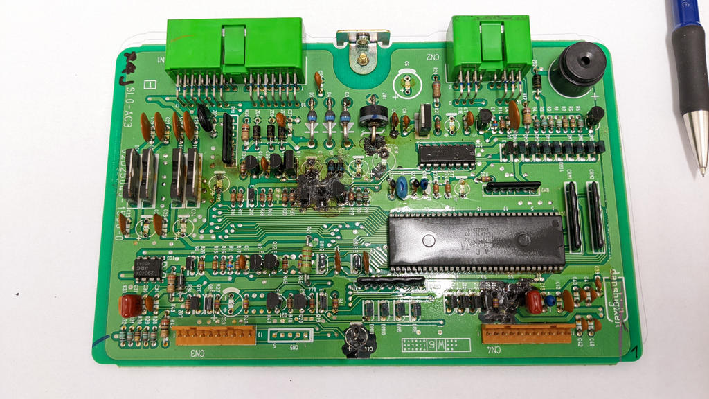
Here are some more details of the affected areas:
Besides the capacitors, several additional components had to be removed, only to be able to clean the PCB:
A first test run showed a working display and buttons but the AC fans did not come on and the fan speed dial wasn't working (the fan stayed in auto mode regardless of the dial).
Using a known good PCB, suspicious parts where de-soldered, checked and compared. It turned out that R19 needed replacement since it was near mechanical failure due to its legs almost eaten away. After a defective Q9 was replaced, the AC fan started working. Q17 turned out to be defect as well and once replace, the fan speed dial was working again.
Sounds like a piece of cake but it's the result of eight hours of measuring, comparing and testing. Not such a smart idea to go to bed when the first birds can be heard .. but finally successful

The backside of the PCB was full covered in conformal coating, the top side was manually touched-up by means of a brush.
New knowledge on broken components and their effect was added to a corresponding blog entry on NSXCB, for future reference: http://www.nsxcb.co.uk/entry.php?2751-Climate-Control-Unit-(CCU)-Repair
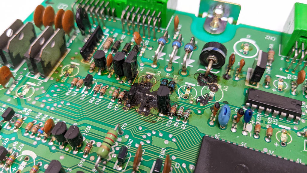
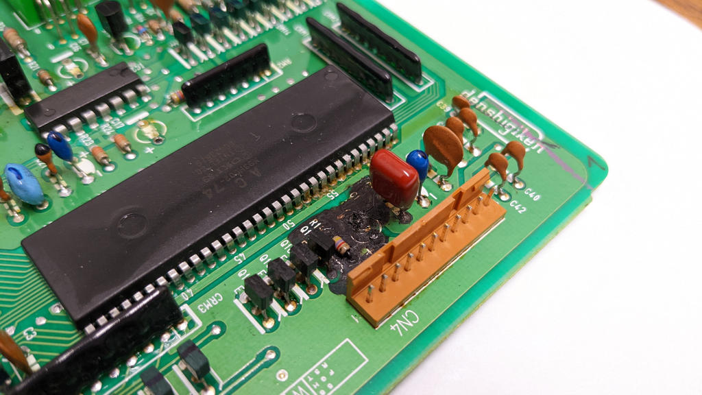
Here are some more details of the affected areas:
Besides the capacitors, several additional components had to be removed, only to be able to clean the PCB:
- Resistor array RM1
- Transistors Q11, Q9 and Q4
- Diode ZD1
- Resistors R19 and R22
- Connector CN4
A first test run showed a working display and buttons but the AC fans did not come on and the fan speed dial wasn't working (the fan stayed in auto mode regardless of the dial).
Using a known good PCB, suspicious parts where de-soldered, checked and compared. It turned out that R19 needed replacement since it was near mechanical failure due to its legs almost eaten away. After a defective Q9 was replaced, the AC fan started working. Q17 turned out to be defect as well and once replace, the fan speed dial was working again.
Sounds like a piece of cake but it's the result of eight hours of measuring, comparing and testing. Not such a smart idea to go to bed when the first birds can be heard .. but finally successful
The backside of the PCB was full covered in conformal coating, the top side was manually touched-up by means of a brush.
New knowledge on broken components and their effect was added to a corresponding blog entry on NSXCB, for future reference: http://www.nsxcb.co.uk/entry.php?2751-Climate-Control-Unit-(CCU)-Repair
Last edited:
")