• Protip: Profile posts are public! Use Conversations to message other members privately. Everyone can see the content of a profile post.

DIY: OEM Alpine Head Unit Capacitor Replacement

Thanks
I have all but given up. I swapped the board from another head unit and I had a working unit from that point. 24 hours later, head unit is dead again. Not sure where the next problem is.
Something to note: a Canadian head unit has a relay connected to middle board that closes when power is applied. A US head unit does not have the relay. There seems to be many different revs of PCAs in these units. Alpine seemed to re-engineer these systems over time.
Willmans has been contacted.
I think I may go for the Willmans new Kenwood innards upgrade if this continues to be a difficult process.


Sent from my iPhone using Tapatalk
 
That is unfortunate. Have you checked to see whether its the same transistor that bought the farm or some other failure?
 
Sorry to hear that! If it is indeed the same transistor that died, it sounds like there is excessive current draw somewhere in the head unit - maybe another leaking cap?

I'm going to pull my head unit again in a few weeks, I can take a close-up of that transistor when I've got it out.
 
Sorry to hear that! If it is indeed the same transistor that died, it sounds like there is excessive current draw somewhere in the head unit - maybe another leaking cap?

I'm going to pull my head unit again in a few weeks, I can take a close-up of that transistor when I've got it out.

No evidence it is the same transistor. I checked it.


Sent from my iPhone using Tapatalk
 
i had an issue with my radio.
i did not use it since a year because the right speakers seems dead, and i think the bose amp was dead.


when i put back my CCU in the car i check for the radio in the mean time and there was no sound at all from it. not from any speakers. so i think it was a radio issue and not a bose amp issue.
i saw your thread and many from Kaz and tried it myself


i put the radio out and obviously there was some caps leaking (mostly the 2200um and the 1000um)


i did the same i did with the CCU, changing the 2200's, 1000's, and 470's from the amp plate and power plate. i had to make a little bridge where a track was gone. i did my best even if i am not please whith it
the tracks was not so corroded as you can see on the picts.
09P2BK1UWxZfp_yFzgrGBBp40Hp5XGMrMLDYmKmEG5cS5bxGmxmVa8_1p_LTf4du91bgsl8zrD30JJa5xIOv_bmKKpR2bwKKDHr_JwZh4oSwuwugboPj96nNerWD6Gi46PkiCGLoM2vUPEFLSvu0wy-o2CaDEJfGQOnSsGK84bSgRLnCzKzMzC3E10NGnAq8vkuVr4cruhrCQXQAjoh_YGWKeUJiMKgLvc7GOJu9PhjysdVv-vpOJMw2IpmVjsn1zxIsxoOSOoZ_w_ljdZ4p-5_t5cOsMl0cTqdu3eReDb9o9Utq7xf0JrPTHQVNbWjSW80GGK8Q2zfJtHyJ_tRPBAYYynSX4sy2jVkzSJlxeh2qWaBGF2O_vADwvOEBHSIWOtMzFhBlToQDPm7Z0qPqJhSfCOguFHhiaLMHSU2amqDw4QHBr1q9xUSRmnj_1e4hpYF83BSygbwgk9nEuyJd_h2sw1_C4QsSEDINhZmrmy8Mo1IQ9G8YX2C9PClqUbvNRewc4Jje-9UFufojsvz-IQZiWGqGFgHZYixtxgAg_T68WwkbKKwQ-ztr3_eODKDsCrB5RwvrgdHukSW-JUcmNVIxygXoX9qAWDqvDahK=w690-h919-no

lZ2K314tSoVuYpQ5Vpxk62dKhk9H1QSNDbNs98UKj51YAOGkZtxWxkfnKrn9muhVr0MSzFuSko6_oKHEQkZeUodOuRZ1UlrPwrFR3BCAgWXIRGkIs0C3-AH0d-SQ6Qoj_fZp4_KcfffmXQVIaIj0xdkEcTkAyEMPfn78ZqQQ2mFcZzNQHsQMGERjHgt2wR5Jd5cROg0WiKZ3-4jUEjp-5P0cAM-Rd-nJdtghgFHaDtDuA3a9osnqqmyCV3pxBqQ7D4FgE5Xm7wgCxW2h0WUZZydoAH8XJy3u4BGcvFjo0eI-4BuvMEAEYRMmzybgRDxhXGxIQNuOIbOpL6ekJ51BihzjbgpRvZ2le49JOZZy6FfXkHQ3paU2L7FuE2O3JcjK4b2Ld59bodW6_oMORkbE9OMqBKuw1f9sxgTORWsFsvMRu7vOaNAzO_X8LVRLyX8-3_GexCnLhYfjR5uWX0FWcFTajp2JzYIO_tTmmrqrF7eFuCLzJunesMj1Ope-b_fL9uTRUiMVTsThqeGII4his55ApFTjwhvTV9aWOzHD_X5ET4SiPHSSzVlWCY3geHHWcZIeS0ZCUtOi80HIBGGAXkf0QcgufccCsq5IrnmP=w1226-h919-no

Z2euxoMd5N278PuuvmnfZTgg1DrflHLw_aYD-8o-AIaX1s_HjNebVaL-pWj93InKZJmt7ZlUGiGFmj-gCUvmlZq6lGu2jnD7P3Pre2Cv1nke-L0iA5fBsQY0vLY5VxfHVmll9RkKX7JiBgA56lkEmOWQridB2CnP360hc53GLGYUwG5MrFk_cyLWF7hNjvX0sxk1OeAE8Nb54uHkgOTgFQUyZGFeIqFJ6erQVHBm1f9XcwjngDGpDU0C8m04zWwGAOxf8mFxsYZw6isKyfJPff5LpxoALxeGgVXh8h2uH9jBLBMhsAueIqA2wnqZ2zWQ-XR2N_i-p_bLadoq1p4vakpOQVGXWzNzqcVUiFl_jXCVSlSRv62w2eNYW8G5gjFhoAqLNaHahtIZpsFdir3csupOh_GGEaj_JQcVAzAME_Y_71A3nCRESuXAwU_RbTZ4XfOyEfihbHjJvSlfQkWoPtqQmogqq_WIMRn9tIRLATCdBQoH5NuPLUTltXbki6yat-VjbIXCTmurrDUUsl4_2UVQ8SmLc2hGrleBQK7Kt3YicsgRi7kkoDdE6kqsjSQnBdl3mncHvAl-xcnrGsVymS-Ex0mDPjknge0lA06S=w690-h919-no

_LUoGtiqnwALmTBfYdmO-Jg9TSZtOE6jbR-iHW1h2nYWwM1Qxah96_0YEvH1Kl6geQZ6JXJK115WXZAVQ7QFIXoTcXK86972TgSUoRdA7sFdwnpSkZRoGlZAC5WWQloGLA3_pkRc2ysLNdQfE34IaWJwOORVzw5vgtCQs5Tc4CTcr3fT-0Gfelqr6rWMLr-v_7dWt6IpXHq8_cmZP6XDufkSgfkrlmUOXi9DqtQ2IWwbCqWRovBhrmdArgIVKRhuj1glpDp8iVujYc7a0-jDEkZm-oRHzaPorYoN6w1zbw6A6CYWNit8aE-UrDMc6deFl1YR2BiNgkSx8czBJDh2IkqxQgaEPhHnEZqrGzbFzWOGxr_mK3hVC1_FLmI-Xvjdgm-ndg2fce6VX68wAJbCL0kEb_YGTTxY0SKvTeDt8RaMjY6w-dkkeuYvaOjirPz9AlaGGhHjd78c8IkYqDc_UttZQ43Ky0_GnlDlwX0jOaff-v1BwCPslJCICDR8U6cwEnZ1_BpjAHfeut6o8PBbqmwOdnqr9daolvwZVPUOsqO2HDo8hIlQEis5LlGUym6viml5ezfDDeljMGTAeUz7oYBgXWxBV7dQ1n6GxBYn=w1226-h919-no


i put everything back together.
now when i put on the radio, all the speakers play!!!! but not very right
the gain seems to be all messed up on each input. radio is scrachy and full of bass, cassette seems overdriven like to much gain too, and the CD charger is very low volume but if i cranck the volume really high the sound is quite good .


i think i have a problem with the op amp 4560? what do you think? it is the only component in the acid path and i saw kaz change them from time to time
where else do i have to search?

thank you for your help

i am still searching for the issue and i cannot find a 4560 opamp for replacement. do some body have some skills in troubleshooting audio electronic here?

thank you
 
Last edited:
The 4560 has been around since the end of the last century, so I am sure there are some other legacy applications that use them that you could salvage one from. However, searching to find one of those legacy applications takes more patience and time than I would be prepared to invest to save a small amount of money.Digikey says that they will ship parts to Europe. The DIP version of the Op amp is sold in single quantities for what would be less than 1 Euro each. Digikey's flat rate shipping cost will far exceed the cost of the a single Op amp so I would be inclined to buy 2 or 3 just to cover a screw up during repair. Perhaps buy all the replacement capacitors for the head unit at the same time as that probably won't change the shipping cost.
 
Just to help some other guy, I was right, my OP Amp 4560 was fried.
I finally could change it. It is a tricky job.
I will test the radio ten to twenty hours in the car now and will coat it with conformal coating when I'll be sure everything continue to work as it should.

https://photos.app.goo.gl/zht3qEpmUHAEWvJK7

And the first song I played with it was period correct!!!

I want to thank every primer that help me on this in this thread, and Kaz with his blog. It is full of pictures that help me to understand and repair this radio myself. Here in France no pro wanted to even open it.

Merci beaucoup les gars

Ps: and now I need to change my TPS
 
Schematics

I have just read through this thread and would like to ask a question and then partially answer it.
Who says there is/are copies of the schematic in Germany or elsewhere? I would be very keen to see it for two reasons. Firstly, if it were a genuine for an early European I would love to see it and compare it to mine (home grown). Secondly, if someone has it, why haven't they used it to make fresh PCB's which is what I intend doing.
Before you all go rushing to ask for a copy there are a couple of problems. The internals of the European are entirely different from the American and Japanese versions. They even use a different processor. The other problem is that I have not verified my schematic....yet. It has taken many many late night hours to create my schematic and I now have artwork for circuit boards and intend using that to prove my design by building a couple of boards and de-bugging any hardware niggles. This has one achilles heel. The processor or more accurately micro controller has embedded code which cannot be (at least by my limited resources) duplicated so the original chip has to be used. Transplant is not difficult but completely repopulating the new boards will be slow. The other boards are relatively simple and I hope to have a full set of replacement blank boards at some point. I can't even give a date when the artwork for the main board will go for fabricating the new boards yet as the auto router was a piece of crap and I have spent too many hours already tidying it up. I will eventually get there, eight months of spare time so far and hopefully I will then find the time to do an American version as I have one 'foreign' head unit as an example. If anyone from Europe reading this has any old redundant head units that are beyond repair, please let me know in case there is a chance of restoring them or for salvage. Most of the IC's are available but I have not sourced all yet. The FFC ribbon cables are available in all except the 11 strand version - I have used a 12 way connector in that location. There is also the question of identifying the discrete transistors. Some can be identified from codes printed on them and others hopefully by testing them, but as I mentioned a few more donor boards would be very helpful in completing this project which is by no means nearing completion. I think I will go and play with my new crank harmonic damper pulley for a while.
 
Glad to see more electronics gurus are getting interested in these units.

In the second video at the start of this thread the narrator says that he has heard from his competition and a friend in the UK that the schematics are available in Germany, but are still in blue-print form. I just emailed the person in the video and asked him who his friend was, or where else he heard this rumor. Wouldn't not be surprised if his friend in the UK is Kaz.

I dropped a line to Alpine as well...you never know.
 
Last edited:
(Trying again, because mobile version is "difficult")

1. Has anybody done a concerted effort to wring the diagrams out of Alpine? Maybe convince them to do a Classic Support program?

2. Replicating the original is PCB's is amazing (LMK where to send my money). However, why not just build a board that can take the OEM in/out connectors and integrate them into a modern software defined radio (with wifi, bluetooth, HTML interface, and the kitchen sink).

I realize this isn't easy as well, but it would turn a hardware job into a software job that is accessible to more people and highly customizable. My guess is that somebody in China has developed a SoC SDR or maybe even use a PC on a board (ie rasberryPI).
 
(Trying again, because mobile version is "difficult")

1. Has anybody done a concerted effort to wring the diagrams out of Alpine? Maybe convince them to do a Classic Support program?

I just tried a contact form here- https://kb.alpine-usa.com/contact.php/ as well as their facebook page at https://www.facebook.com/AlpineUSA/

They also have a twitter page https://twitter.com/alpineusa

I would urge you to do the same-strength in numbers, etc.

This might be something to involve NSXCA with as well. warrenw any thoughts here?
 
There were several generations of the head unit, plus different parts of the world, the product was different. Even a Canadian car had a different model head unit number that a US model of the same year.
The other issue is the head units have a Honda p/n, not alpine numbers.
Nothing is impossible until a firm no is returned.
Hey, I bought a Bose footwell amp brand new from Bose for about the same cost as getting one rebuilt.
If you don’t ask, the answer is always no.

I would be willing to ask on behalf of NSXCA if someone would draft a request that includes part numbers, serial numbers, board numbers, etc.
My opinion: the head unit isn’t that good of a unit to spend that much time on it. The quality is poor compared to today’s head units, and features are lacking.
I gave up, and went with the Williams unit, and love it. There is another solution being designed that uses classic car replacements, that may be even better.


Sent from my iPad using Tapatalk
 
My opinion: the head unit isn’t that good of a unit to spend that much time on it. The quality is poor compared to today’s head units, and features are lacking.
I gave up, and went with the Williams unit, and love it. There is another solution being designed that uses classic car replacements, that may be even better.
I'd go with a Willmans unit too, old-school design but up-to-date features. I'd only touch the OEM unit if it's about to fail but haven't failed so far and someone wants to keep it forever. If it failed the risk and labor/hours spent on an old unit is not really worth it.

What does the Willman upgrade cost?
 
Off topic, but relevant...

Stereo choices cut to the heart of what the NSX is now, and it will become. There are many "better" options out there, but so what? A new Mustang is cheaper, more reliable, faster, and in almost all ways objectively a better car.

As these cars become more collectable the question will shift from, "Is this stereo better than the original?" to "Is this stereo original, and in good condition?"

If we wish others to see the NSX as a valuable classic then we should probably pay more attention to preservation than to improvement.
[MENTION=18431]warrenw[/MENTION], I can send markings/PNs from my 1992 alpine unit when I open it up in January. My suspicion is that, while there were changes over the years, having a OE schematic of any version would make deciphering the rest much easier.
 
In Europe we have the problem that UKW-radio-wave might be cancelled in the near future which is DAB+. So no radio anymore. Radio only broadcasts sh*tty mainstream music which is not everyones taste. One might still have audio cassettes but who has a tapedeck at home anymore and - even more important - the time recording them?

So you could end up with an nearly non-working unit and a useless antenna. Keeping a useless unit 100% stock versus a slight upgrade to use it in the future it not that bad. :)
 
Assembling a bunch of available modules to get the functionality you want and stuffing it into the head unit chassis is probably fairly easy. If you want to retain the OEM look, integrating it with the existing front end controls and getting it to drive the existing display could be the more challenging bit. The display could be the biggy because it dates from the late eighties and who knows what kind of interface it uses, probably proprietary. If you were willing to use something like an HD44780 LCD display (or some suitably sized fancier; but, current TFT display) behind the faceplate, then it could be easier. However, at that point the appearance deviates from OEM and maybe you should just go with the William's option.

One of the realities of modern electronics is that support lifespans just get shorter and shorter. If you upgrade the head unit, whatever you stick in there will have an even shorter support lifespan than the OEM head unit. The OEM head unit may lack some of the functionality of more current units; but, at least most of its problems are repairable.
 
I've been on 'prime for so long now that somebody sent me a dead/disassembled head unit for free back when everyone was tossing their units to install the hawt new double DINs.

I'll dig it up and start posting images, maybe we can figure this out.

The Williams is a non starter for me as I want the look/feel of the original unit. I am boring in that way (actually I've been told I'm boring by a past GF too) that I like stock cars.
 
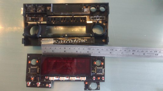
I pulled the display board, but not the actual display...it is buried under an acrylic lens. (I'm a CS, not an EE, so any help educating me is appreciated)

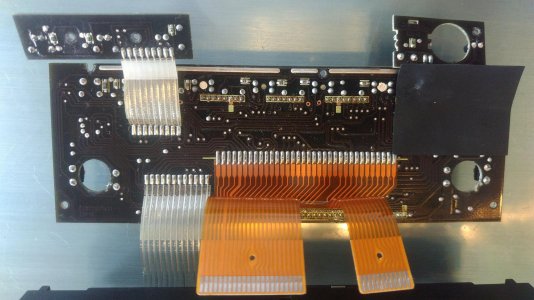
The control chips are dual NEC D6700GH (next line down 9039K7) and everything fed through a couple of ribbon cables. Everything else is either a pot (volume, treb/bass)or a momentary switch on other boards or connectors.

The D6700GH is labeled as "a static display driver" and is still being made, or at least knocked off, today. I presume the "static" part is the chip supplying a steady voltage some predefined [shape] that lights up...

So the question is: How do I (somebody) build an interface into this display using a rPi or similar?

nsx_radio_display_front.jpg

nsx_radio_display_rear.jpg
 
I pulled the display board, but not the actual display...it is buried under an acrylic lens. (I'm a CS, not an EE, so any help educating me is appreciated)

The control chips are dual NEC D6700GH (next line down 9039K7) and everything fed through a couple of ribbon cables. Everything else is either a pot (volume, treb/bass)or a momentary switch on other boards or connectors.

The D6700GH is labeled as "a static display driver" and is still being made, or at least knocked off, today. I presume the "static" part is the chip supplying a steady voltage some predefined [shape] that lights up...

So the question is: How do I (somebody) build an interface into this display using a rPi or similar?

I had pulled my head unit apart years ago to clean off something on the inside of the faceplate. Apparently I didn't pay close attention to the details as I assumed that the display was some type of LCD display. Based upon that chip number that chip just appears to be a driver for a fluorescent display. It can accept 48 bits of data and hold that data in a register and use that data to drive up to 47 individual display segments. So, to make use of it, you would have to figure which output pin is driving which segment on the display. 2 x47 = 94 seems like an awful lot of segments for the NSX display. Outputs 1-10 can also be configured to read the data and drive LEDs, so maybe that is why they have two of the chips with one for the LEDs in the buttons. I just glossed over the data sheet, so I am guessing that the status of bits 1-47 drives segments 1-47. The driver requires a micro controller up front to accept data from the radio or CD / cassette / whatever, interpret that data and package it into the 48 bit long data 'thing' that it then dumps to the driver chip to update the individual segments on the display. I am betting that on the main board or the display board that there is a chip like an NEC UPD170xx or UPD7500x which is a NEC micro controller that accepts data from the front end devices and packages it into the 48 bit long package that drives the display.

If the display is unique to the NSX or other Alpine devices, figuring out which data bit drives what segment would be a bit of work. I expect that you could do it experimentally by setting up a micro controller to dump the 48 bit long data 'things' to the display driver and see which bit lights up what segment. This would allow you to create a map for the display. Doable; but, not a trivial exercise.

People have mentioned using software definable radios. They are available and can do AM and FM; but, as far as I am aware don't do AM below about 20 Mhz so are not usable with the AM broadcast stations in North America. You can get Wi Fi / Bluetooth radios to bind to your telephone and stream audio to the head unit. Of course, with the existing display, any identifying data that comes with the content is not displayable on the existing head units predefined display. Essentially the same problem with using flash RAM on a Grom with the existing NSX head unit - it only supports 6 CDs / directories with up to 99 files in a directory.

There are lots of nifty displays out there. Unfortunately, the form factors for the nifty ones that I have seen don't exactly match up with the NSX display according to your measurements. I used a 44780 LCD display when I hooked up some probes to measure EGTs on another car.
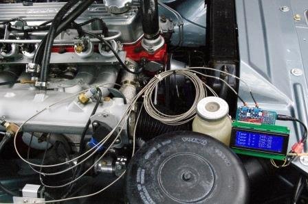
EGT measurement.jpg

The display is 3.8 " long, so slightly smaller than the NSX display according to your photo. It has 4 lines of 20 5x7 characters so quite readable and can probably be configured to replicate everything on the NSX display (a little coding required for non standard characters). The display is available in RGB so you should be able to match the NSX display color. I had white on blue because it is easy to read. The software libraries to drive the display are readily available for Arduino / Teensy / .......
 
I suspect a bit mask to run the display, each bit could toggle a display element. This sounds reasonable, but Dunning-Krueger is telling me I have no idea.

Anybody know how use an Arduino or rPi to interface with the display chip D6700GH?

The mobo chips are:
1. Alpine 51T35170W01
2. Alpine 35168W02
3. Fujitsu MB88306 (CMOS expander)
 
Are you asking about doing the bit masking in an Arduino? This tutorial covers that and the particular example that they go through would be the process that you could use to generate the series of bits that are fed to the input of the D6700.

https://www.arduino.cc/en/Tutorial/BitMask

In the example, they generate a serial stream of 8 bits. This requires a data word of 2^8 (256 in decimal). The D6700 requires a stream of 48 bits so it needs a data word of 2^48 which is roughly 2.814E12 in decimal. That is a really big number. I am not a Comp Sci guy; but, somehow I expect that bit masking might not be the process unless the data is broken down into 6 x 8 bit words which are transmitted sequentially. If there are 4 - 7 segment displays for numbers, I estimate that there are about 44 unique display segments on the display. If the D6700 is also used to drive the LEDs, that would explain why they need two of them.
 
Theoretically, I can write code and move bits around. I seem to have gotten paid well for doing it for a long time, so far so good. It has been a very long time since I have done ML and bitwise op's, but I should be to muddle through it again at a 101 level.

It should be trivial to shift a single bit up/down the 48 bits to see what it does. Going through the whole 2^48 and monitoring the display would indeed be a "small matter of programming."

What is magic to me is the physical I/O to the display chip. I have a bunch of rPi's, a couple of breadboards and I was able to toggle some LED's on/off and flip some relays. I was going to use them for home automation, but life got in the way and there they sit.

So I guess I am asking how I send the contents of a register through the Alpine ribbon cable's so I can start flipping bits? Looks like there are ~34 leads, presuming two are power/ground...I have 32 left over and I would like to shift a bit through them.

Where do I start?
 
Back
Top