• Protip: Profile posts are public! Use Conversations to message other members privately. Everyone can see the content of a profile post.

Help diagnosing a voltage drop under high loads

I do wonder if there is similar behavior with a stock car.


Thanks for all your help on this!

I expect so. Without involving superconductors it is impossible to eliminate voltage drop. It is all a matter of whether it creates a problem. On a stock engine you have less horsepower; but, smaller injectors. If the OEM arrangement runs with similar PW values I expect that the voltage drops would be similar.

As a final observation, the operating voltage really only affects the opening time of the injectors. Once the injector is open, it is not particularly sensitive to operating voltage unless the voltage rally goes in the sewer. At really large PW values where you seem to be getting the max voltage drop, the PW values are long enough that the variation in opening time caused by the drop in supply voltage will not make a material change to the volume of fuel delivered with each pulse. The problem is more acute at low load when the injectors (particularly really big injectors) are operating with very small PW values. At short PW values the error in opening time becomes a consideration because it can make a material difference to the amount of fuel delivered per pulse. This is primarily an issue of idle quality and for OEMs, making sure the car remains compliant with emission limits. In your particular case, since the voltage drop at low engine loads is smaller, any impacts are probably trivial.
 
Today I measured the voltage with the engine off and it seems like it’s probably a calibration difference like you mentioned. I turned the car to IGN with the navpod on to see the can bus data, it ran the fuel pump etc

* Voltage on volt meter at ecu on A23 / A25: 12.8v
* Voltage reported by ECU: 12.5v
* Voltage on gauge: 12.8v

That is a 0.3v difference which jives with the data under load where it was 12.6v from the ECU and 12.9v at the CAN module.

It def makes sense that it really only affects injector opening. And that despite the drop, the ecu will keep them open for the correct amount of time. Thanks again
 
Yeah I still have a voltage drop. It is a little worse since the sc rebuild, but only by .2v or so. Not totally sure why yet though. I don’t know if there is a drop at the pump. The drop seems to be isolated in the injector/ecu circuit.

Fuel pressure is fine for me. It steadily rises to redline and peaks at around 62psi at 8-9psi, which is consistent with a 1:1 rising rate FPR. I have an aeromotive FPR, idle pressure is about 45psi at 10.Xpsi vacuum. Pressure sensor is at the filter
 
At the cost of complexity you might consider a 12v to 15v voltage booster for the injectors.

Patching the symptom when one can't cure the disease is a tried and true engineering solution.

I find such things are temporary only if they don't work.
 
Thanks for chiming in! I’ve been thinking about doing something to supply better voltage to the ecu and injectors but wasn’t sure what. That sounds like something worth looking into. Or maybe using like a PMU? Not sure

A couple new developments:

Since the sc rebuild, the voltage under load has been a bit lower as mentioned above. .2v - .3v or so. Thinking it may be a ground or something as that’s all I moved in the tear down / install process. I checked everything, but they all seem good.

It wouldn’t be an issue except, a couple times at WOT, the ecu has totally shut off, which is new. It’s weird, unsettling, like a fuel cut. I let off and it comes back on, yay. Still tracking that down, but it feels related. I assume the voltage dips below 12v for a second or something. The logs never show under 12.2v but maybe that’s cause it dips and shuts off before logging the dip? The only times it’s happened have been when the car has been out for a while and things are probably pretty heat soaked. The first couple trips to redline are fine. Idkwtf

The car is torn apart again for other reasons, but I’ve been spending a lot of time with the service manual, looking at wires in the car. I did find that the IGN signal from the fusebox is around .4v lower than the ACC signal, also from the fusebox.

It has a pretty hacked up harness. The car has had a ton of gauges in it, splices, aftermarket stuff, and probably a lot I haven’t discovered yet. The worst part is that the alarm install is super invasive with a bunch of jank crimps. The alarm is now my no 1 suspect.

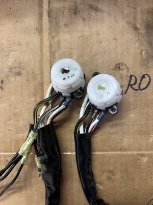
I replaced the ignition harness this weekend thinking it would be easy. Turns out mine had been hacked and spliced for the alarm immobilizer. They spliced one of the battery feed wires and the IGN output. Maybe solution?!?!

AC300845-5023-4E92-A944-84D3221334C0.jpeg

All kinds of stuff runs through that blk/yel ignition wire, notably the fuel pump, igniters, and the cabin IGN signal.

I haven’t tested it yet for reasons, but hoping it at least solves the cabin ign signal issue. Maybe it also improves the ecu power situation? A guy can dream. The ecu power is from a different circuit, though, directly from the battery to the main relay.
 
Once a wiring harness is hacked up it becomes the No1 suspect.

From the posts, you seem to be chasing down some very small voltage variations that really are to be expected in a vehicle.

To fix the symptoms: isolated aux battery for the ECU+injectors, power conditioners, and boosters. A big cap on the ECU power supply might do wonders for these spurious issues; (motormouth is an EE FYI).

I've worked for government and we were given vehicles that we weren't allowed to modify past what special equipment or features that were provided by Transport. We would then pile on all types of inverters, boosters, conditioners, and whatever we needed to get the equipment to work.

It would also be amazing to have mission critical stuff wig out because the cigarette lighter power connector jiggled too much on some off road excursion. It also should be noted that with Government it is easier to get $10M than it is to get $100, so lotsa bodge on multi-million dollar equipment.
 
If the ECU is actually shutting off and then restarting (the CEL will illuminate following a restart), that is more than just a voltage fluctuation. The 'chips' on the ECU will operate at 5 volts or perhaps 3.3 volts if it is later technology. Depending on the ECU's on-board voltage regulator, a low drop out regulator should allow the ECU to function just fine down to an input voltage close to 6 volts (for 5 volt chips). Other stuff such as injectors, ignition coils, drive by wire etc. will not function correctly; but, the ECU will survive. If you are getting a compete shut down and restart that seems more like a power loss rather than a voltage dip. I would be looking at the integrity of the ignition switch - main relay - ECU path.

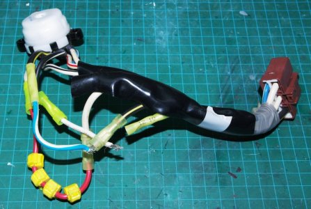
A previous owner left me with this bit of creativity so I have first hand experience with wiring integrity.

IMGP4077.JPG
 
If the ECU is actually shutting off and then restarting (the CEL will illuminate following a restart), that is more than just a voltage fluctuation. The 'chips' on the ECU will operate at 5 volts or perhaps 3.3 volts if it is later technology. Depending on the ECU's on-board voltage regulator, a low drop out regulator should allow the ECU to function just fine down to an input voltage close to 6 volts (for 5 volt chips). Other stuff such as injectors, ignition coils, drive by wire etc. will not function correctly; but, the ECU will survive. If you are getting a compete shut down and restart that seems more like a power loss rather than a voltage dip. I would be looking at the integrity of the ignition switch - main relay - ECU path.

A previous owner left me with this bit of creativity so I have first hand experience with wiring integrity.

View attachment 183027
I still shudder when I see that picture. The bare wires...
 
Noted @drew on the minor voltage drops. Some kind of dedicated power for the ecu and injectors is probably in my future.

Love the taps on that red wire @Old Guy.

The ecu is an aem series 1, so probably a lot more touchy than the oem ecu. I don’t think I’ve ever seen it turn on the CEL, but the internal logs cut, and the navpod data goes flat just like when it’s starting up. Honestly the dumb aem box is probably the problem with the cutout. Check out this thread. Same problem. It’s pretty grunty, but the solution was sending it back to aem to replace a board or to resolder stuff. Also seems like other people had it happen only when hot.

(Yo honcho, should I just get a haltech already? Honestly the nexus r3 would probably solve both problems….)
 
(Yo honcho, should I just get a haltech already? Honestly the nexus r3 would probably solve both problems….)
Just do it. :) I think a lot of your issues are stemming from that crusty old AEM. I feel like anyone with FI should be on a modern engine management system. EMtron SL is good too, but I like the Haltech design and user-friendly interface.
 
The ecu is an aem series 1, so probably a lot more touchy than the oem ecu. I don’t think I’ve ever seen it turn on the CEL, but the internal logs cut, and the navpod data goes flat just like when it’s starting up. Honestly the dumb aem box is probably the problem with the cutout. Check out this thread. Same problem. It’s pretty grunty, but the solution was sending it back to aem to replace a board or to resolder stuff. Also seems like other people had it happen only when hot.
The power up CEL test is a standard feature for all OEM ECUs. If you have an aftermarket ECU, I don't know whether it utilizes the CEL or has the power on test feature if it does.

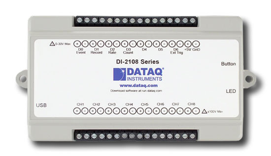
Absent a power on test I would be inclined to consider an external stand alone data logger to monitor the +12v supply to the ECU. You can get 4 channel loggers that need to be attached to a laptop (no on board memory) for less than $50. The laptop is a hassle so for less than $200 you can get them with internal memory capability (SD cards, USB drive). These guys have a 4 channel stand alone
There are probably others that may be cheaper. The logger should tell you whether you are getting fluctuations on the car 12v system that could be affecting the ECU.

If you are Arduino skilled, there are inexpensive data logging shields that use SD cards that you can attach to your Arduino to record analog data captured through the Arduino's A to Ds. I have done that. Aside from coding the firmware the files are recorded in csv format so you need to develop something in Excel or similar to display the data.

Pre Covid, I was helping a couple of member deal with the problem of random power interruptions. Both ended up wiring up external stand alone data loggers to monitor 12v supply. One problem was traced to a fuel pump supply problem the other was a combined problem of the alternator wiring / front engine mount. The alternator wiring had been slightly moved and was shorting out to the body ground when the engine moved. The engine was moving (more) because the front mount was failing so that one had two contributing factors.

The external data logger should allow you to determine whether the problem is originating inside the ECU or outside the ECU. If the problem is outside the ECU, there is no point in replacing the ECU just to find out that the new one does exactly the same thing as the old one.
 
Last edited:
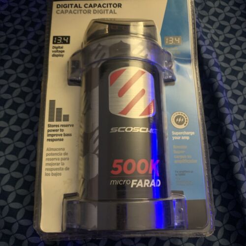
on the note of fixing the symptom despite the disease... Perhaps you can try a capacitor. I used something like this in my "sound system" days. Just pick one from a reputable brand. I see a ton of no-names on Amazon. Not sure how good those are. 500k or 1 megafarad is probably more than enough to prevent that ECU from shutting off.. and if it still does it's probably a problem with the ECU? Regardless, it might be time to go with a LinkECU

 
Following up on this for posterity. The car has a number of new parts in the ECU / injector circuit:
  • A new Link ECU
  • New ID1050x injectors, they’re are slightly higher impedance than the RCs
  • A new Bosch 90amp alternator (old was 80amp denso)
  • Brand new, not-spliced ignition switch
TL;DR: the voltage behavior is similar. Still a drop, derp

!BUT! The new Link ECU is a lot better at logging than the AEM, so I have a bit more information.

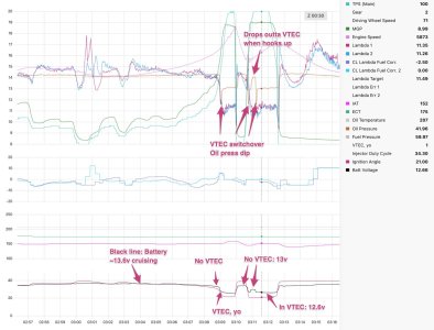
I think a big part of the drop is from the VTEC solenoids. The most pronounced drop happens immediately when it goes into VTEC. The chart below is extra obvious because, after the shift into 3rd there is a little wheel spin, increasing the RPM (pink line) and putting it in VTEC for a sec. Then when it hooks up, the RPM drops out of VTEC. The little bump on the black line at the bottom shows it gaining some voltage while out of VTEC, despite high load, then back down when it's in VTEC again:

voltage-drop.jpg

I couldn’t see this with the AEM. The Link logs all parameters at the same frequency, same number of samples per second. With the AEM, battery voltage was logged at a lower frequency than other params, so I couldn’t see the drop immediately at VTEC switchover.

Another thing that is the same: the ECU still sees a slightly lower voltage than the chassis (13.6 - 13.8v in the logs vs 14.2v on the chassis gauge). I thought maybe the AEM sucked so it reported a lower voltage, but not the case. I guess that difference is the circuit, not the ECU.

Generally with the new ECU and other new parts, the voltages seem a little better and the drop is a little smaller. My conclusion for now is that this is probably normal, or at the very least, probably fine.
 
Last edited:
Back
Top