Always good info @
Mac Attack. Thanks for being so generous with your knowledge!
My primary purpose for the airbox would be for metering the airflow properly for the ECU tune. I feel like the most accurate way would be thru a MAF sensor first, or a MAP. I also want an airbox for *some* sound suppression (I know i'm crazy right?). I've listened to a few and they're just simply too loud for me in the open trumpet format.
I believe for a stock motor the MAF looses accuracy if placed in an intake tube larger than about 3" - 3.5" but I don't know this for sure. I can only observe from other MFGs who've implemented ITBs. My tuner and I are up for the challenge of tuning an ITB setup because, you know me... if it doesn't drive perfectly on the street, i'm just not interested. I feel like the vacuum tree solution that SOS/Hayward uses with the MAP sensor just isn't robust enough. I don't blame SOS for not selling it anymore. I could never do only Alpha N/TPS tuning for the kind of driving I do. At a min I need a MAF or a MAP solution. We are considering implementing multiple maps that rely on a Alpha N *with* MAF/MAP correction. I believe my HKS computer can take a few different inputs simultaneously. I suppose correction via O2 wideband is also possible. Lastly, air filter is optional but desired. I don't mind the slight loss of power here as long as the loss is not egregious.
BTW... a big ass box blocking my rear view would drive me insane too. Also, thanks for mentioning that very important point about resonance but particularly how it's not a concern when designing an air box. That's definitely above the classes I took in college
")
So now.. if I was to go ITBs these would be my open questions.
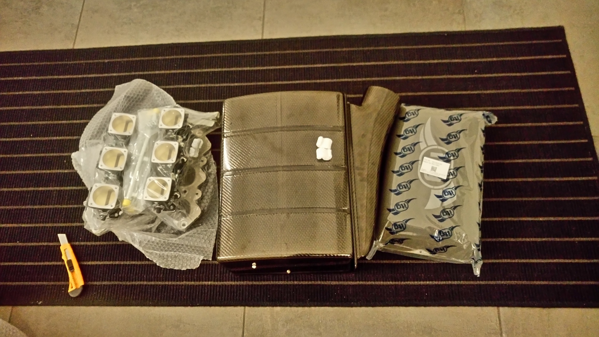
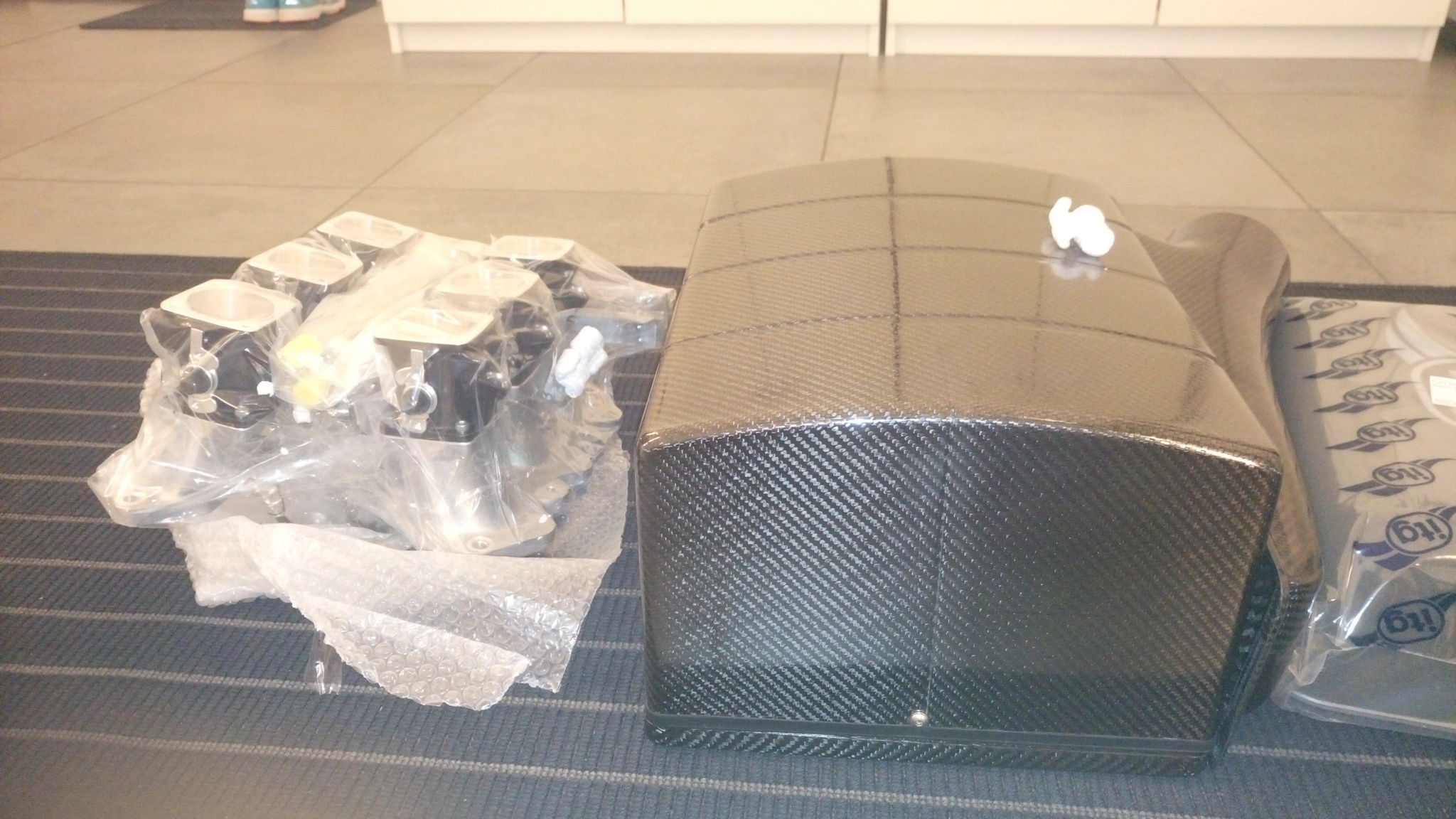
1. How to best design an intake plenum pre-ITBs? i.e. optimal volume and what type of air entry orifice.
2. Use a MAF or MAP
3. Where to mount an air filter? Cone element or flat element? Use the OEM air filter box perhaps?