A German radio from a 1992 NSX arrived in the worst possible state - it wasn't turning on. So far only half of the radios in this state could be saved since the acid damage can be quite severe and there aren't replacements for all of the parts in the radio. If proprietary chips are affected it's over quickly.
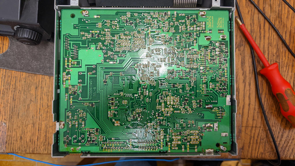
The bottom of the lower PCB looked unaffected, which is a good sign - heavy acid damage often penetrates the PCB and can be seen from the underside, too.
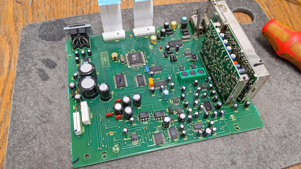
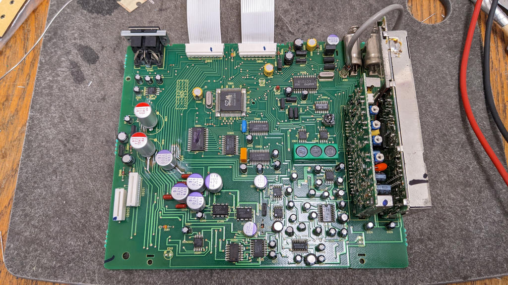
After disassembly and looking at the top side, there was no damage visible either, it rather looked like a PCB with audio issues at worst.
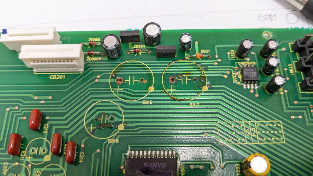
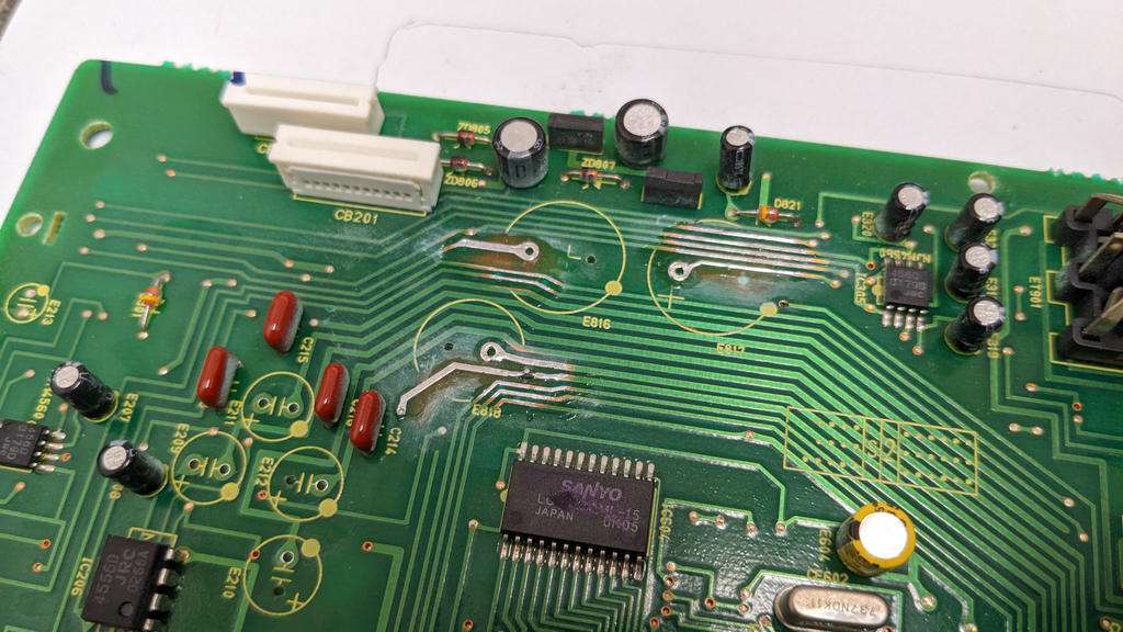
Looking under the large, black capacitors there was the usual damage but not too severe. Good on one hand but potentially troublesome on the other since repairing that damage would probably not turn it into a working radio again.
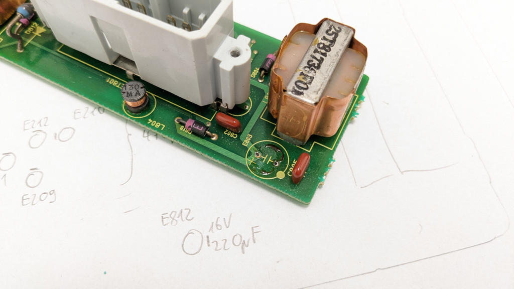
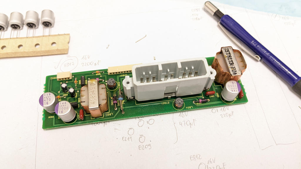
The Power PCB showed so little acid damage that it was sufficient to clean everything - all the tracks were still OK. To make sure there's no future trouble, all through-hole connections are re-flowed with fresh solder.
The bottom PCB got cleaned by means of a glass fiber brush, one suspicious VIA strengthened by inserting a thin wire and the raw copper areas covered with solder.
After installing the new capacitors on all PCBs, the radio was ready for a first test run.
Exactly as predicted, the radio would not turn on. Since the damage to the PCBs was minimal it would be unlikely that the micro controller or the RAM are affected. Since it's advisable to start with the simple things first, I went to look at the on/off button. There are two pins to measure the state of the button: Where the button's flex cable is connected to the lower PCB and at one of the two big flex cables connecting to the middle PCB.
In a working radio, both pins are at 5 V and pulled down to 0 V when the button is pressed. When pressing the button, this radio showed almost no change at the button's flex cable and no change at all at the large flex cables. The micro controller can't be expected to switch on under these circumstances.
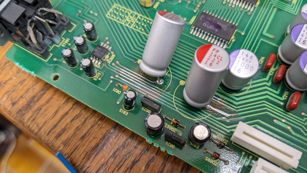
Beside carrying the same signal, the two pins are directly electrically connected, usually measuring less than an Ohm - not on this radio, though. Here the multimeter showed above 1 MΩ which is way too high. Further checking the traces revealed that the high resistance was located on a trace between the button's flex cable connector and the VIA and near one of the large capacitors.
Using the fiber glass brush, another broken trace was discovered. It went unnoticed since it was just a small dot and hiding underneath the yellow paint, marking the mounting area of the capacitor. Once repaired, the resistance measurement between the two pins was back to normal and the radio turned on just fine.
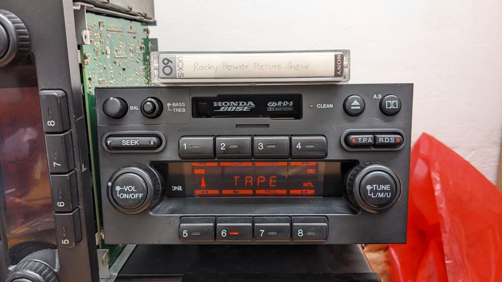
I'm happy it's been such a relatively easy affair and all follow-up checks (CD changer, radio and cassette) passed without issues.
The bottom of the lower PCB looked unaffected, which is a good sign - heavy acid damage often penetrates the PCB and can be seen from the underside, too.
After disassembly and looking at the top side, there was no damage visible either, it rather looked like a PCB with audio issues at worst.
Looking under the large, black capacitors there was the usual damage but not too severe. Good on one hand but potentially troublesome on the other since repairing that damage would probably not turn it into a working radio again.
The Power PCB showed so little acid damage that it was sufficient to clean everything - all the tracks were still OK. To make sure there's no future trouble, all through-hole connections are re-flowed with fresh solder.
The bottom PCB got cleaned by means of a glass fiber brush, one suspicious VIA strengthened by inserting a thin wire and the raw copper areas covered with solder.
After installing the new capacitors on all PCBs, the radio was ready for a first test run.
Exactly as predicted, the radio would not turn on. Since the damage to the PCBs was minimal it would be unlikely that the micro controller or the RAM are affected. Since it's advisable to start with the simple things first, I went to look at the on/off button. There are two pins to measure the state of the button: Where the button's flex cable is connected to the lower PCB and at one of the two big flex cables connecting to the middle PCB.
In a working radio, both pins are at 5 V and pulled down to 0 V when the button is pressed. When pressing the button, this radio showed almost no change at the button's flex cable and no change at all at the large flex cables. The micro controller can't be expected to switch on under these circumstances.
Beside carrying the same signal, the two pins are directly electrically connected, usually measuring less than an Ohm - not on this radio, though. Here the multimeter showed above 1 MΩ which is way too high. Further checking the traces revealed that the high resistance was located on a trace between the button's flex cable connector and the VIA and near one of the large capacitors.
Using the fiber glass brush, another broken trace was discovered. It went unnoticed since it was just a small dot and hiding underneath the yellow paint, marking the mounting area of the capacitor. Once repaired, the resistance measurement between the two pins was back to normal and the radio turned on just fine.
I'm happy it's been such a relatively easy affair and all follow-up checks (CD changer, radio and cassette) passed without issues.
")

