• Protip: Profile posts are public! Use Conversations to message other members privately. Everyone can see the content of a profile post.

SCREWED! The Tale of my "Rebuild" (long winded, sorry slow day at work)

Might have been just a vaccuum leak. How much was the repair bill, or you could call him and verify it :wink:?

It was 2004 that my engine had a high pitched metallic rattle when I got off the throttle. The mechanic who told me it was something in the VVIS system has since left the shop so I can’t ask him exactly what he did to get rid of it. The total bill came to EUR 7370.70 but that included other things as well such as overhauling the transmission. Have you heard of the VVIS system rattling for other reasons than what is being discussed in this thread?
 
It was 2004 that my engine had a high pitched metallic rattle when I got off the throttle. The mechanic who told me it was something in the VVIS system has since left the shop so I can’t ask him exactly what he did to get rid of it. The total bill came to EUR 7370.70 but that included other things as well such as overhauling the transmission. Have you heard of the VVIS system rattling for other reasons than what is being discussed in this thread?

I haven't heard of it but I can imagine if the VVIS system had a vaccuum leak, it might cause erratic opening and closing of the butterflies which might cause a rattle :confused:.

I just had a friend bore scope my VVIS system and all was well. Very easy to do for some peace of mind - Thanks Again Dave! Mine is a 1991 with 120,000 hard driven miles.
 
I think it's a good idea to get the engine numbers from the cars that are having this failure. Allong the lines of the snap ring range?
 
It was 2004 that my engine had a high pitched metallic rattle when I got off the throttle. The mechanic who told me it was something in the VVIS system has since left the shop so I can’t ask him exactly what he did to get rid of it. The total bill came to EUR 7370.70 but that included other things as well such as overhauling the transmission. Have you heard of the VVIS system rattling for other reasons than what is being discussed in this thread?
I am getting this exact sound. Actually it's been there awhile. I always thought it was a weird sound for "valvetrain" noise.
 
I did this over the weekend. It took me about 6-7 hours. I am an "okay" weekend wrencher and took my time and also changed the fuel filter and tidied things up. Biggest unexpected time sucks were changing the fuel filter and scraping the old gasket off of the vvis plate as mine was quite crusted on. It also takes quite a bit of time to remove and reinstall every butterfly screw. Your forearm will get a good workout. :) Removing the injector plugs also took more time than expected, but after figuring out the first one, the rest went pretty quickly. I think Chris quoted 2-3 hours and that's about right IMO.

The only tips I have would be

1) if you can get the injector plugs off, you don't have to remove the injectors or fuel rail at all. This would save time and money if your injector seals are fresh. I was changing out my injector seals anyways and removing the rail and injectors first made it easier to unplug the 2 injectors closest to the crank pulley

2) If you remove the butterfly screws all the way, there is pretty much no way to get it back in without cross threading it which means you risk having the screw head strip. The process I used was to back out the screw about 3/4 and then put the loctite (I used loctite 680) into the back side (hole) and also on the exposed threads. Then screwed it back down. That sped things up a lot and removed the risk of stripping the screw head.

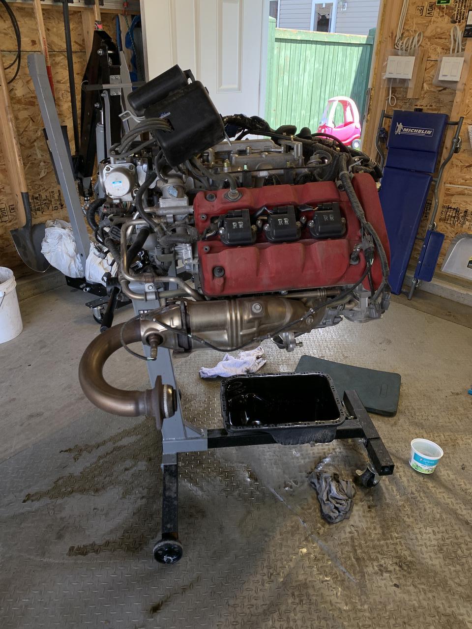
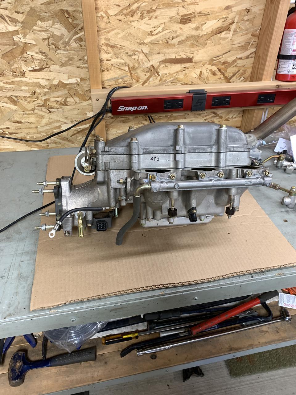
Here are some pics of the job.

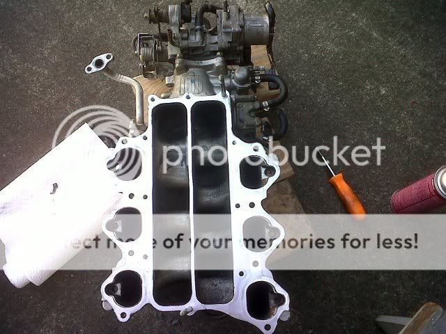
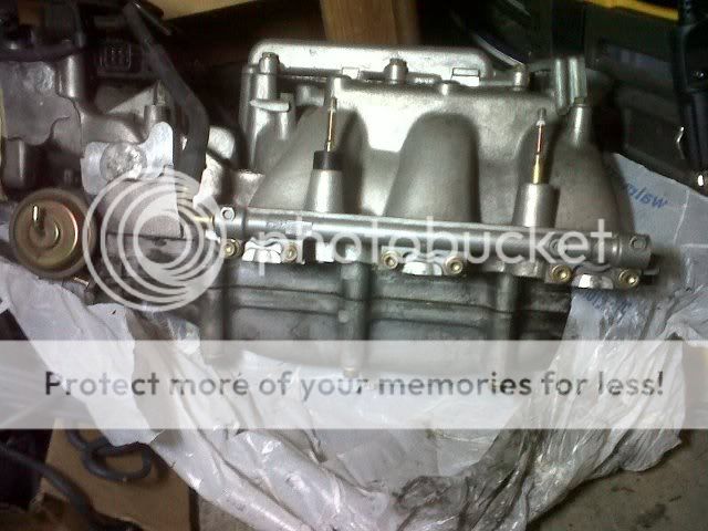
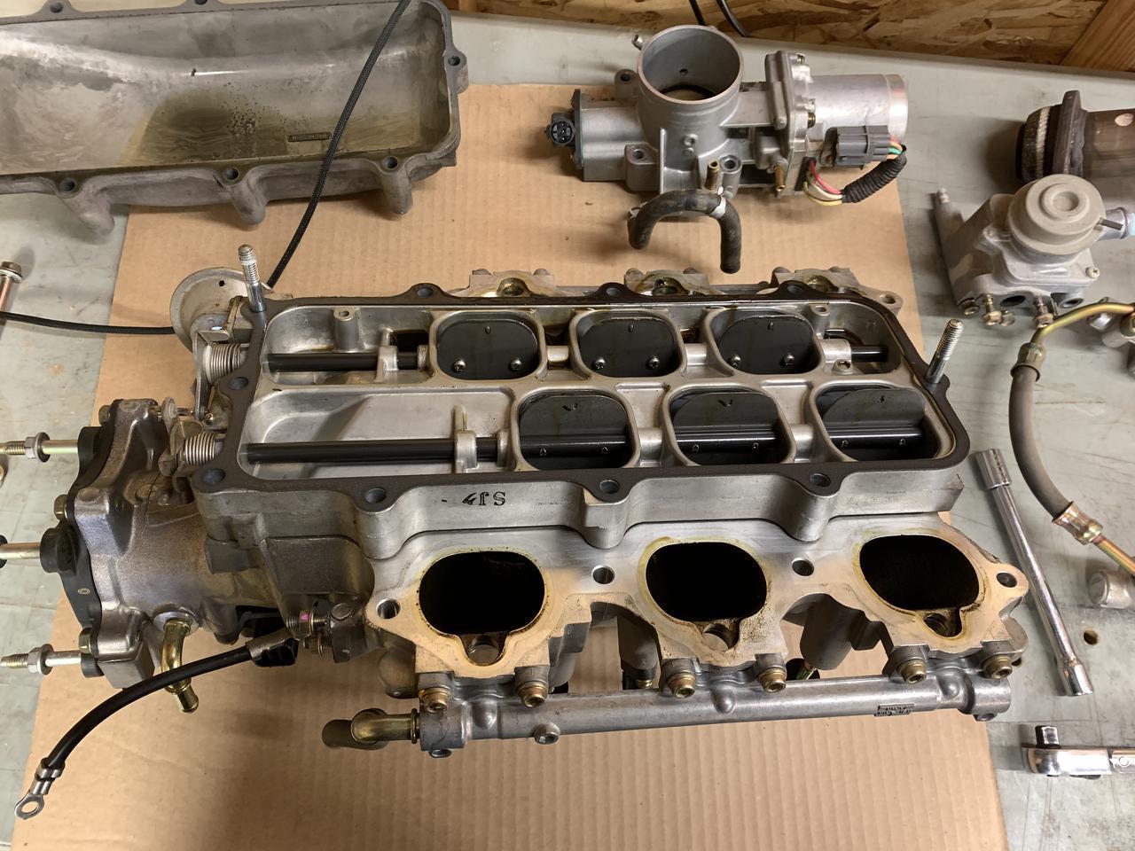
Under side of the IM. This is a good idea to "blow" out the small vacuum rails using some brake cleaner.

IMG01467-20111231-1200.jpg


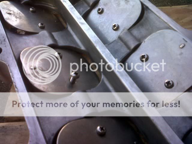
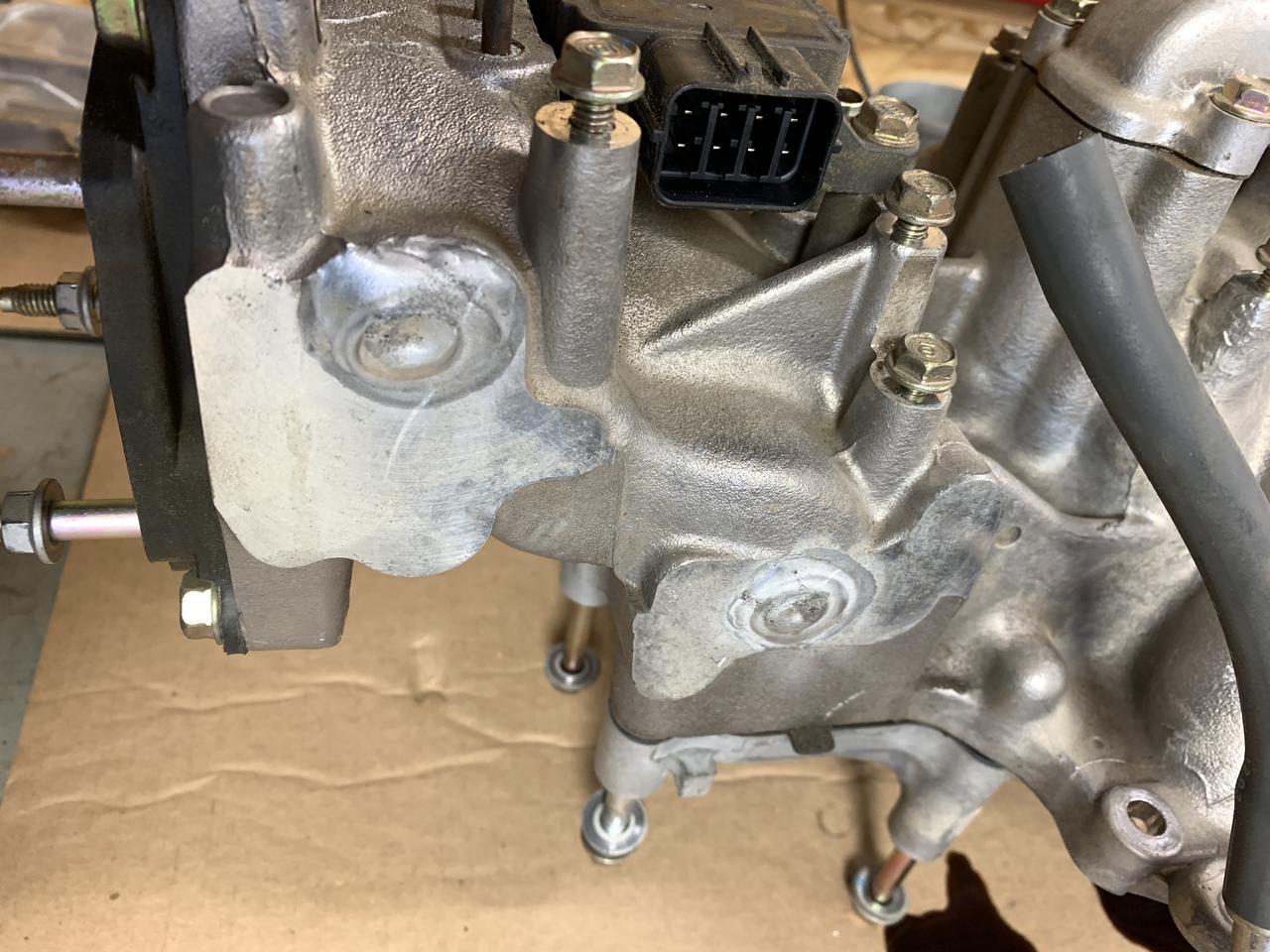
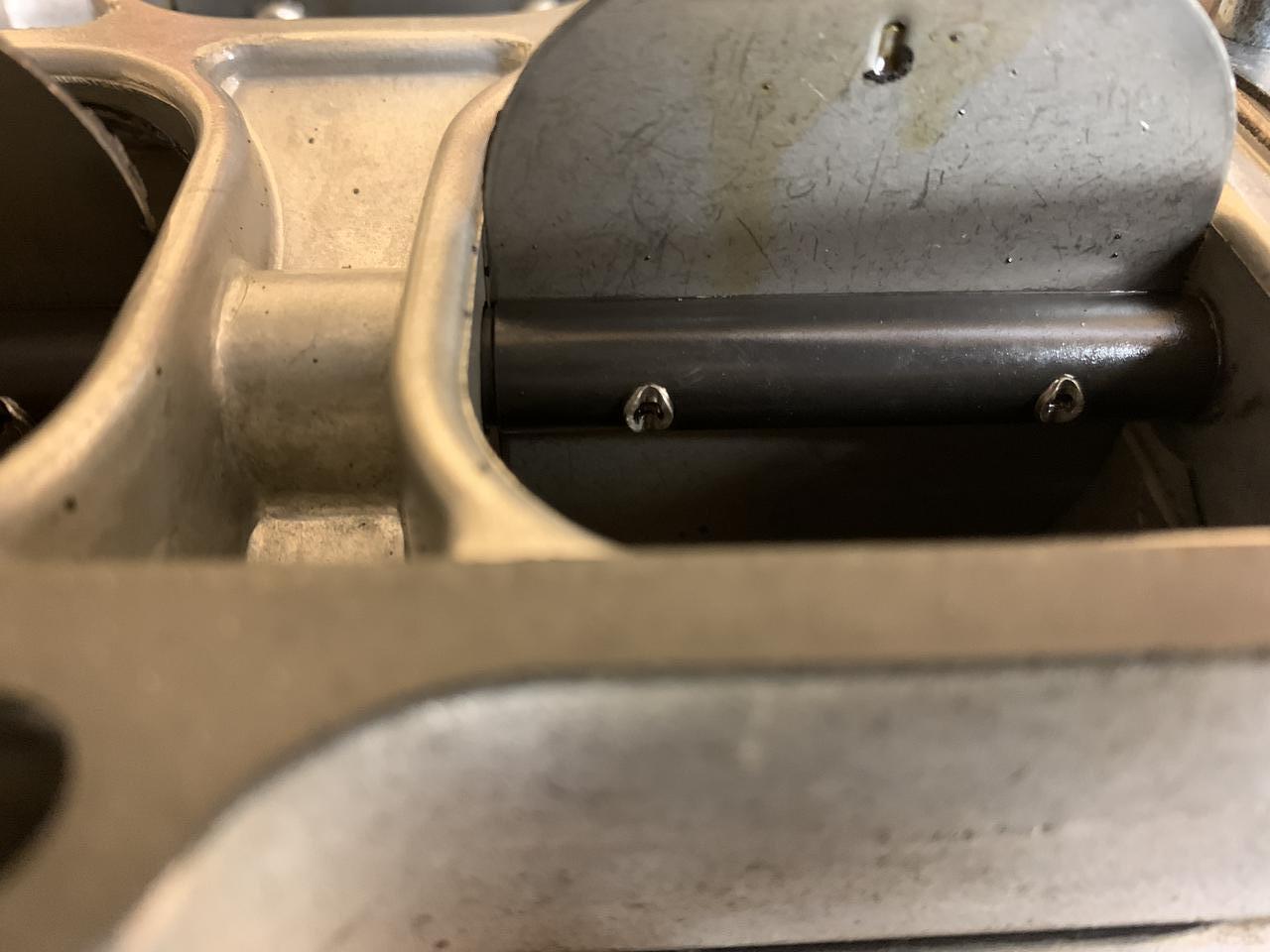
This pic shows the butterflies. The screw that is extended is what I call "3/4" and is how far I would unscrew them before putting loctite on the threads and in the hole on the back side.

IMG01464-20111231-1119.jpg


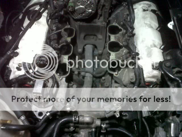
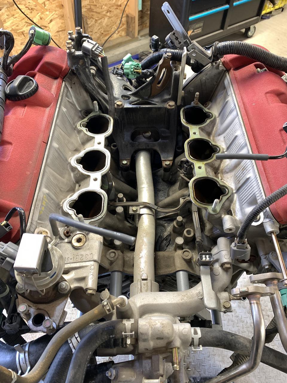
I think you can figure out what this is:

IMG01461-20111230-2133.jpg


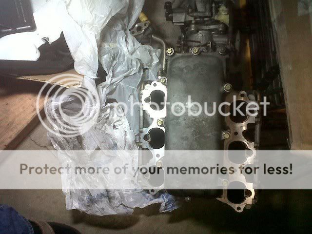
Once you have the IM off, you can see why those two gaskets are big money. It looks to be a phenolic gasket with a rubber and metal ring around each port.
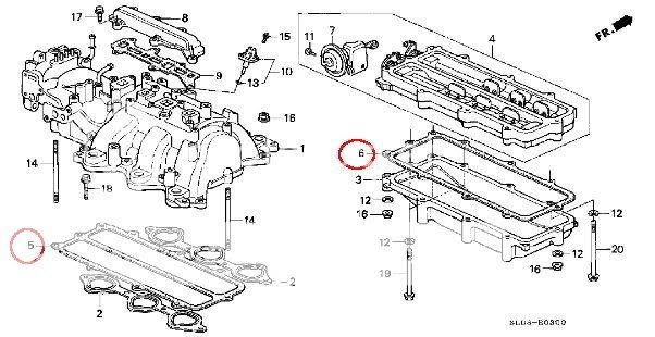
My Parts list:
- 18721-PR7-A01 x 1
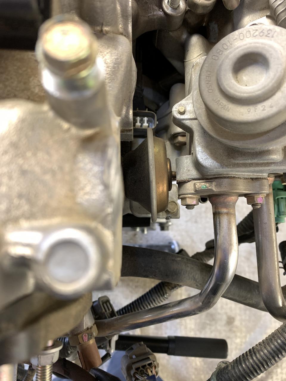
EGR gasket (I only removed one side of the tube - left the side attached to the IM as shown in the pic).

- 90428-PD6-003 x 4
fuel line banjo washers. You can get away with only 2 and leave the line that connects the two fuel rails together, but if you're taking the injectors out to change the seal I would recommend buying 4 and separating the two rails

- 17141-PR7-A01 x 1
IM gasket between the VVIS plate and IM

- 17142-PR7-A01 x 1
IM gasket between the VVIS plate and chamber

optional - injector seals all of them. They're around $60 a set.
optional - 2 x IM gaskets (between head and IM). They're $60 a pop and you need two. I opted to reuse them even though the manual says to replace. After seeing the condition of mine, I would reuse them again.

I will also mention that I recently changed all of my coolant hoses. This R&R would be a lot less fun with crusty old coolant lines. I want to say 6 or so coolant lines were removed and about 1/2 gallon of coolant. A rebleed of the system wasn't necessary. I did open the bleeders after reassembly and refilling with coolant, but no air bubbles flowed out nor did the engine "drink" more fluid after the coolant was re-added.

Some more notes - I turned every screw on my '95 manifold (this is the one that had a loose plate and 2 screws that fell off) and they took quite a bit less torque to bust them loose compared to my '91 manifold. Even the ones that had not turned yet and were still aligned properly. My '91 manifold was fine - all of the screws were tight and I doubt they would have loosened on their own. I have no doubts the loctite is plenty strong enough to hold the screw after feeling the amount of torque required to remove the screws. I am also happy to report that I found the "missing screw" that I had assumed my motor had eaten and survived. The middle section of both screws that fell out were worn smooth, so the swedgeing held on for quite some time while the screws slowly worked their way out.

[edit] I also put some of the wicking loctite (290) on the TB butterfly screws just because it sounded like a good idea when another primer mentioned using it on TB's
 
Last edited:
VVIS_dyno_chart.jpg


From what i gather the above image shows that na cars (non sc/turbos) loose mid-range power. This is from the sos thread i initially linked. Again just my interpritation i may be way off lol

waiting for the wise ones to chime in :biggrin:

I wonder how this would change with a car that has a full equal length header, high flow cats, and high flow exhaust? I may just remove mine any adverse effects other then a loosing a lil mid range? Im going forced induction as soon as NY state gives me my dam retro check. How porous is the cast material can you polish the intake runners to compensate loosing a lil mid range?
 
/subscribed....

IMG01461-20111230-2133.jpg


What part connects directly to those runners? I'm trying to visualize how it all fits together.... what goes under the VVIS plate / butterflies? The diagram only shows the intake manifold and the VVIS plate...

nsx_IM_gaskets.jpg
 
Last edited:
That's all there is. The IM and VVIS plate and the chamber underneath it sit in the void between the heads

In this pic, the 6 round-ish holes on the IM connect to the head. The VVIS plate and chamber cover the 2 long holes in the center (note the IM in the pic is upside down so you're looking at the bottom).

IMG01467-20111231-1200.jpg


The VVIS plate and chamber (#3 and #4 in the diagram) sit in the void in the center between the heads where you see the alternator bracket and the long pipe. The void is actually quite deep and below the level where the intake holes on the heads are.

In regards to the post above about smoothness and polishing the intake, there is a lot written about smooth vs rough for IM design and tuning (injector swirl, laminar flow, etc). I don't really have any working knowledge of how that all translates at the wheels, but I don't think polishing the runners and intake port on the head is going to do what you want here

Hmm right so does the vvis allow air to enter the IM thru the void unfiltered?
 
So the dyno shows the change up in torque but, has anyone entirely deleted the VVIS and tried the butt dyno? Is it really really that noticeable?:confused: Just exploring all avenues here.
 
Here you go enkrypt3d. English has failed me again, but these pics should answer the question

IMG01476-20120104-1926.jpg


IMG01475-20120104-1925.jpg


Davidf, can't you just cap off the vacuum line going to the VVIS and then it will stay open and you can test it out for yourself? Or maybe this will trigger a CEL, but I wouldn't think so
 
Last edited:
Here you go enkrypt3d. English has failed me again, but these pics should answer the question

IMG01476-20120104-1926.jpg


IMG01475-20120104-1925.jpg


Davidf, can't you just cap off the vacuum line going to the VVIS and then it will stay open and you can test it out for yourself? Or maybe this will trigger a CEL, but I wouldn't think so

Oh ok so its sealed up in there thanks!
 
I just did this mod and a couple things to report;

  • Did not take long, just make sure you place all your bolts in order and keep a good sense of where all the vacuum lines go. Maybe 4 hours tops with cleaning everything.
  • I did find two (2) butterfly plates loose. Numbers 1 & 2. The screws were still swagged in but the plates definitely could move around on the control rod. Glad I pulled this out.
  • Found oil pooled in the VVIS manifold chamber and some more in the base. Don't have an idea where it came from but it sure looked like motor oil and not excess from my air filter. Had to be 100ml or more.
I didn't go Chicken Little because of this thread's beginnings. I spent a ton on this motor when I first purchased the car. Had Driving Ambition rebuild it from top to bottom. I plan on going FI very soon so the delete was going to happen anyway but it was a bit unnerving looking at those loose butterflies. I'll sleep better tonight.


BTW, SOS has a nice little delete kit.
 
Any more updates on this? Trying to get a better idea of the affected years. So far it looks like later '90s
 
I just did this mod and a couple things to report;

  • Found oil pooled in the VVIS manifold chamber and some more in the base. Don't have an idea where it came from but it sure looked like motor oil and not excess from my air filter. Had to be 100ml or more.

I found liquid in mine too, but I soon realized it wasn't oil, it was throttle body cleaner.
 
Guys we should all take this thread seriously. I had my manifold taken apart to be cleaned and I found the same thing. I feel so lucky that the screws didn't do any damage to my motor. I think I'm just going to delete this piece for safety.
 
I recently bought a cheap borescope to check out the screws of my VVIS plates. Thankfully, all 12 screws were still where they should be and none of them were backing out. Here’s what one of the VVIS plates looked like:

VVIS_plate.jpg


Personally, I’m going to keep my VVIS in place for engineering reasons. It gives our engines two separate intake plenums (one per cylinder bank) until the valves open and then one shared plenum when the engine computer calculates that it’s beneficial. That’s pretty much the same system Ferrari just put into the 458’s intake. Getting rid of that would make the NSX’s engine simpler but also somehow out of date.
 
I didn't want to start a new thread, and this is the first one that popped up on Google, but I wanted to jump on the bandwagon of confirming my intake flapper screws. I don't know if it's in my mind but it feels like the flaring on my screws is more pronounced than in the pictures earlier in this thread. My car is a 2005 6MT.

yG941AZ.jpg


They put this air injection port thing right in the way of the air line which was annoying. I had to remove it so just means waiting for more gaskets.
jDFiPUY.jpg


n9uRqDb.jpg


5DvoIQL.jpg


...I'm not saying I can do a better job at welding because I can't but it seems a bit odd they would just hand weld some holes.
ncxUgKS.jpg


KPS8dcK.jpg


DcrcBky.jpg


All of my rubber coating on the edges basically came off by hand. I'll clean these up in totality after I get the screws welded. My original question was going to be about the more pronounced flaring on my flappers but the more pictures I look at it's pretty much identical.
 
Back
Top