@
Russ ,
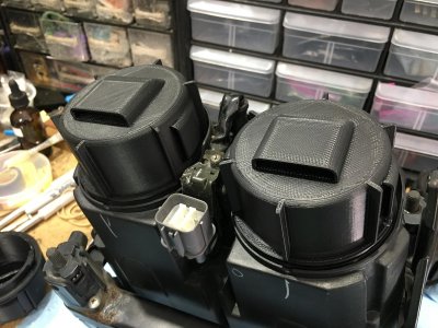
Thanks. What software did you use to create these? I’m tempted to figure out how to eliminate the vents, since I suspect there is a reason Mother Honda made these units sealed and the LED companies are saying OK to run under dust caps.
I would note that the Honda caps are only designed to contain the connectors, which shouldn't generate any heat. With the stock set-up, all the heat is generated at the bulb. While the LED's will generate less heat overall (since they draw less current and are also more efficient) some heat will be generated in the dust cap instead of inside the lens, although it is continuous with the air outside the lens but inside the sealed housing.
But if the LED bulb companies say the LED cooling fans and fins are fine inside dust caps, you'd think they'd tested it. I'm surprised by that considering how much heat comes out of mine, but I'll go with their expert opinion. I'm waiting for a reply from Boslla. Edit: Boslla says their bulbs work fine up to an ambient of 221 degrees F (100 C).
*******************************************************
Hello Timothy,
Thank you for contacting us. Our LED headlight bulbs have good heat dissipation and can work normally from -94° F to 221° F. So it’s okay to install with the dust cover on, Vents are not necessarily required.
Regards, Julia Boslla Team
*******************************************************
Edit: I did a test with the bulbs on for 60 minutes in a housing with solid dust caps. The air inside the caps was barely warm, definitely not 100 degrees. The heatsink was hot enough that I played hot potato getting it out, but not that hot. I think I'm going with solid caps.


.jpeg")
.jpeg")


