• Protip: Profile posts are public! Use Conversations to message other members privately. Everyone can see the content of a profile post.

[Help!!] CV axle/axle rebuild gone wrong.

Joined
28 April 2015
Messages
23
Hi Prime, I'm a lurker who never post anything but I'm trying to get some help as I messed up a big time on a simple CV boot rebuild.


I was doing a cv boot replacement yesterday, everything went smooth and okay until the markings on the spider and the rollers have decided to disappear while disassembling.

I used a regular marker to mark the spider/rollers/shaft ( i somehow assumed that it would be fine) before removing the spider and the rollers from the shaft. Took them out and saw the markings were still there and then I tossed them in the big towel to clean them thoroughly.. and yes the markings were gone..

I tried fitting the spider on the shaft without the original marking, I guess teeth are specifically spaced so spider can't be reinstalled on some random position but I found 2 different positions where I can reinstall the spider. does it matter which position I put the spider in?


As long as I can somehow manage the 60 deg. between the inner and outer spider I think I should be okay, but is there any way I can rebuild the rollers into original position without the marking? ( all 3 of these look identical and fit on all three legs on spider... )

Or am I screwed now and have to fork out to buy a new set of axles...

any help would be appreciated, thank you so much in advance.
 
go to nsxwiki

"repairing your nsx"

2.1.3 transmission/drivetrain

scroll down to transmission/drivetrain

"repacking cv boots"

lots of pics and directions.

good luck!
 
I don’t think you can recreate the original orientation but if you are careful about the 60-deg offset then I imagine you will be fine.
 
Indeed - bad luck. However, as jwmelvin notes, as long as you preserve the 60 deg phasing between the inboard and outboard joints you theoretically should be OK. The service manual says to mark the spider on the shaft during disassembly; however, on page 16-7 of the 1991 manual there is the following note

Note: Stagger the inboard joint spider and outboard joint spider 60 deg apart. To ease assembly, mark alignment marks on driveshaft and spiders before disassembling them.

I read into the 'ease assembly' note that the marking is just to assist in getting the correct 60 deg phasing on reassembly rather than getting the spider in exactly the same position on the shaft. Also, Honda sells replacement inboard and outboard joints separately from the complete driveshaft. If you can install a new replacement joint with an unmarked spider, that would suggest that the spider position on the shaft does not require an exact positioning as long as you maintain the 60 deg phasing.

The spider fitting on the shaft in only two positions is interesting and I didn't see any mention of that in the service manual. Does that fitting in only two positions apply to both the inboard and outboard joints? If so, the one that gives the correct 60 deg offset would be the one to pick. If both give you a 60 deg offset - then flip a coin?
 
Last edited:
No worries about not placing the spider back into the same position on the spline.

In fact, if the spider came off the spline with ease by just pulling it by hand without the use of puller, then you do want installing the spider at different position of the spline.
That is the method used by the companies refurbishing the drive shaft to prevent the loose spider making clicking noise after refurbished.
At some places, they even stake the spline to make the fitting very tight on re-installing the spider but OEM shaft is hardened multiple times so not easy.

If the spider was already loose and placed back in the same position, it will cause clicking noise within short time even with the fresh grease.


When you install the spider at different position, you need to punch it in and the used brake piston or something similar becomes handy.
Just make sure to install it in the same direction (hope you can remember or study the wear markings to tell which side was facing the end of the shaft) and at the same side (inboard or outboard).

The key is to create 60deg offset between the inboard and outboard joints.


For the roller position, ideally, you want placing them back at the same position/orientation inside the joint housing so that it won't generate any friction heat under load.
If placed in wrong position/orientation, you may feel some resistance or even not possible to slide them into the groove/recess of the joint.

Before applying the grease, try the pre-assembled spider/roller/shaft assy inside the cleaned joint housing and move in/out at multiple angle to feel for any stress/friction.
If no abnormal movement/friction, you should be fine.


Make sure to adjust the amount of air left inside the boot while tightening the boot band. Very important.


Several examples here; http://www.nsxcb.co.uk/blog.php?1811&blogcategoryid=37


Kaz
 
How do the mating surfaces look? Are the three spider nubs or whatever you want to call them perfectly vertical? Don't laugh - but I've seen these bent slightly in high torque applications. It's a failure point from what I've seen.

That's interesting about the spider fitting in only two orientations. I didn't notice any difference on the shaft splines or the internal spider splines. They all looked uniform to me, but then again, I had alignment marks scratched in and didn't try to assemble them any other way.

If the surfaces are wearing fine, then I would just reassemble them and not worry about it!
 
I don't buy the exact same position argument anyway. In other cars you can get wrid of axle noises when you change the outer/inner axles joint from left to right and right to left. As long if it's 60 deg apart it's ok. When I refurbished mine that was NOT the case from the factory. So what? The only thing that might play a factor is that each spider gets the same roller again. But even here a measurement of the diameter of each spider will tell you a lot.
 
First of all, thank you so much for all your inputs! I really appreciate you guys taking time reading my post and willing to help out.

Unfortunately I barely have any time during weekdays to work on the car, but I'm going to do my best squeezing at least an hour everyday to fix this problem while taking care of my 17 month daughter after work. going to be tough since she is super needy. :D
 
[MENTION=12044]ofdlt10[/MENTION] - Yeah I already read Kaz's post. thank you, Wiki is awesome!

go to nsxwiki

"repairing your nsx"

2.1.3 transmission/drivetrain

scroll down to transmission/drivetrain

"repacking cv boots"

lots of pics and directions.

good luck!
 
Last edited:
@jwmelvin - that's what I wanted to assume but I wanted to get some light shined by NSX experts on here.. :D

[/QUOTE=jwmelvin;1963170]I don’t think you can recreate the original orientation but if you are careful about the 60-deg offset then I imagine you will be fine.[/QUOTE]
 
Last edited:
[MENTION=26435]Old Guy[/MENTION] - Yeah, I saw the 'ease assembly' part. I assumed that spider fitting should be okay as long as I can keep the 60 deg for in/out joints.

When I have time to reassemble the shafts this week I am going to take some pics with markings on positions where spiders can sit on the shaft. pictures > thousand words, right?

Indeed - bad luck. However, as jwmelvin notes, as long as you preserve the 60 deg phasing between the inboard and outboard joints you theoretically should be OK. The service manual says to mark the spider on the shaft during disassembly; however, on page 16-7 of the 1991 manual there is the following note

Note: Stagger the inboard joint spider and outboard joint spider 60 deg apart. To ease assembly, mark alignment marks on driveshaft and spiders before disassembling them.

I read into the 'ease assembly' note that the marking is just to assist in getting the correct 60 deg phasing on reassembly rather than getting the spider in exactly the same position on the shaft. Also, Honda sells replacement inboard and outboard joints separately from the complete driveshaft. If you can install a new replacement joint with an unmarked spider, that would suggest that the spider position on the shaft does not require an exact positioning as long as you maintain the 60 deg phasing.

The spider fitting on the shaft in only two positions is interesting and I didn't see any mention of that in the service manual. Does that fitting in only two positions apply to both the inboard and outboard joints? If so, the one that gives the correct 60 deg offset would be the one to pick. If both give you a 60 deg offset - then flip a coin?
 
Last edited:
[MENTION=25737]Kaz-kzukNA1[/MENTION] - Thanks Kaz, I love your posts and blogs, really helps a lot on doing DIY. real life pictures with directions/cautions are so much better than the manual book.

I'm so glad to hear that I actually need to install the spider at the different position, that solves the headache I carried for past 2 days. It does all make sense too, that fittings should be tight to prevent the looseness.

In fact, as I was disassembling both shafts, 2 of the spiders came out by just myself pulling it with my hand and the other 2 I had to use jaw grab. And when I test fitted the spider with the original marking I made, it was sliding in pretty easily with small force. After reading what you wrote, I am going to disassemble the other shaft again and reinstall the spiders on different position of the spline.

(I don't have a brake piston lying around but 36mm socket I used to remove the axle nut worked perfectly to press the spiders in! )

As for the roller position, I will clean them again and try to dry fit them on the joint housing to feel for any faulty movements/friction. I mean.. as long as they slide up and down fine without noticeable distortion I should be fine, right?

I didn't even think about the air left inside the boot, but it makes sense! After adjusting the shaft length before tightening the boot band, I should open up a boot a tad bit to control the air right?

Thank you so much again Kaz, I really appreciate it!


No worries about not placing the spider back into the same position on the spline.

In fact, if the spider came off the spline with ease by just pulling it by hand without the use of puller, then you do want installing the spider at different position of the spline.
That is the method used by the companies refurbishing the drive shaft to prevent the loose spider making clicking noise after refurbished.
At some places, they even stake the spline to make the fitting very tight on re-installing the spider but OEM shaft is hardened multiple times so not easy.

If the spider was already loose and placed back in the same position, it will cause clicking noise within short time even with the fresh grease.


When you install the spider at different position, you need to punch it in and the used brake piston or something similar becomes handy.
Just make sure to install it in the same direction (hope you can remember or study the wear markings to tell which side was facing the end of the shaft) and at the same side (inboard or outboard).

The key is to create 60deg offset between the inboard and outboard joints.


For the roller position, ideally, you want placing them back at the same position/orientation inside the joint housing so that it won't generate any friction heat under load.
If placed in wrong position/orientation, you may feel some resistance or even not possible to slide them into the groove/recess of the joint.

Before applying the grease, try the pre-assembled spider/roller/shaft assy inside the cleaned joint housing and move in/out at multiple angle to feel for any stress/friction.
If no abnormal movement/friction, you should be fine.


Make sure to adjust the amount of air left inside the boot while tightening the boot band. Very important.


Several examples here; http://www.nsxcb.co.uk/blog.php?1811&blogcategoryid=37


Kaz
 
Last edited:
[MENTION=12356]Mac Attack[/MENTION] - When I was cleaning them, they looked pretty flat. and Yes, questioning that makes perfect sense, high heat/high torque is always a problem when it comes down to metal no matter how strong it is.

I will lay them down on a flat bench table when I have a chance later this week and check the surface level.

Thanks for suggesting that, I didn't even think about it!

How do the mating surfaces look? Are the three spider nubs or whatever you want to call them perfectly vertical? Don't laugh - but I've seen these bent slightly in high torque applications. It's a failure point from what I've seen.

That's interesting about the spider fitting in only two orientations. I didn't notice any difference on the shaft splines or the internal spider splines. They all looked uniform to me, but then again, I had alignment marks scratched in and didn't try to assemble them any other way.

If the surfaces are wearing fine, then I would just reassemble them and not worry about it!
 
@goldNSX - Before reading multiples of posts and also the manual, I wanted to think the same way. they are all identical parts fabricated from the same factory, why bother right? but then again there's always a chance of deformation due to heat/torque as some ppl mentioned.. If this was a math test I'd say F' it I don't care but it's our NSX so I wanted to be better safe than sorry Lol.

I have decided to fit them and reinstall rather than buying a new one. After reading everyone's input, I think I'll be fine as long as I keep the spiders with 60 deg position. -knock on wood- If by any chance something goes wrong, well I can be the guinea pig and people will learn to use a better marker than a $0.50 sharpie...

I don't buy the exact same position argument anyway. In other cars you can get wrid of axle noises when you change the outer/inner axles joint from left to right and right to left. As long if it's 60 deg apart it's ok. When I refurbished mine that was NOT the case from the factory. So what? The only thing that might play a factor is that each spider gets the same roller again. But even here a measurement of the diameter of each spider will tell you a lot.
 
Last edited:
I may have not got my spiders back in the right place, but did the 60 degree check.
Install one spider complete, inside and outside snap rings.
Then install the second one - only inside ring.
Set the shaft on a flat surface - it should sit evenly on two of the lobes on one end of the shaft and be right on the tip
of one of lobes on the opposite end. If it looks off a bit you can move it 1 spline at a time until you get this relationship.
You should see this preserved as you rotate the shaft 60 degrees.
Sorry - I just looked at my pics from last year - lots of bearing shots, but not the shafts.
..
Did you re-pack the roller bearings? I did mine because you are so far into the job.
..
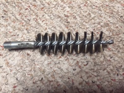
I used a 1.5 inch flue brush to clean the splines in the hubs, see Ebay Tough Guy 2XTD4.
Made re-assembly easier
IMG_2316.JPG
..
Kaz's posts on the UK board helped a lot.
Good luck.
 
Last edited:
For adjusting the air inside the boot, please refer to the photo in this thread. Please scroll down to the 5th photo;
http://www.nsxcb.co.uk/entry.php?2183-Eng-Refresh-LMA-Health-Check-etc-73

I just use tiny but hard/solid tube that comes with spray can such as penetrating oil, Carb/INJ cleaner, etc.
Just needs to be hard enough so that it won't be squashed even when the boot band is tightened.

Tighten the outer/larger diameter band first.

Then, tighten the inner/smaller diameter band together with the tube as in the photo in the above link.

You could sandwich the tube at the outer/larger side but the grease may block the tube so better to stay as in the photo.

After setting the joint or drive shaft length and the boot at half way between full compression/extension, just pull out the tube.

People who competes in auto-x (autocross) session, they tend to leave the small portion of the tube there to 'vent' the air but not required for street driving condition.


Kaz
 
Hi,

Kaz, i have some questions about this:

- how do you adjust the air if you leave that little tube in there permanentely ?
won't it work like a permanent vent ? If so, won't grease get out through it?

also, how do i know how much air is good? by pressing the boot?

Thanks,
Nuno
 
It's permanent vent and that's why it's called 'vent' method in competition field and not for adjusting the amount of air inside the boot, like for street driving condition.
There are several pros and cons but off topic from OP so I'll leave them from this thread.
If you search, you will find tons of them.

The grease won't come out from the tube. You only allow tiny amount of tube behind the boot band.
If it does and comes out like melted ice cream, your grease is already broken down too far and no longer good.

If you study the geometry of entire drive shaft on our NSX, the lateral angle against the gbox/tyre and imagine how all the parts move under various suspension movement/load, you will understand this.
Another reason why you need to be extremely careful when changing the rideheight, suspension geometry, output torque, reverse torque including tyre, etc.

For adjusting the air, please move the boot to full compression/extension to understand where the middle point is.
Set the outboard joint (spring inside) and the drive shaft length at the specified length, set the boot to the middle point and pull out the tube.
For street driving condition, you won't be generating massive heat so no need for the vent.


Kaz
 
Bringing this thread back up. I'm converting my auto to manual and I know that the right side axle is a different length spec for AT vs MT. Is it possible to adjust my AT axle to the correct length for MT? Or, do I have to buy a MT specific axle? I'm going to fully rebuild and re-grease the CV joints. I've seen [MENTION=25737]Kaz-kzukNA1[/MENTION] use what looks like a piece of wood to tap the end of the driveshaft (with the other end being against a cement wall) to adjust length. Is this how you do it?
 
Jumping on this, cause it's good to know information for when I attempt to rebuild an outboard joint that was removed in haste without making any markings whatsoever, lol.

Hope your build is coming along, Paul. I need to start on your thread and read up/get caught up, but I have a feeling I need a nice, long rainy day for that, haha.

It is- slow but sure. As with most complex projects, there are a lot of sub-projects involved (disassemble for paint, box and sell unneeded parts, clean and refurbish old parts, engine teardown and refresh, transmission conversion, interior conversion, etc.) With the basement nearly done, I'll be able to devote a lot more time to it! You'll probably need a couple rainy days to catch up! :D
 
>Is it possible to adjust my AT axle to the correct length for MT?

The axle half shafts are the same from either AT or MT, there is no difference.


>Or, do I have to buy a MT specific axle?

The intermediate shaft IS DIFFERENT. This is the shaft that extends from the RH side of the transmission and is mounted to the engine with a bearing carrier.

The AT shaft is about 10mm shorter than the MT shaft.

It might be possible to just reuse the AT intermediate shaft and just have 10mm less engagement inside the transmission, I did not attempt, but it seems foolhardy. The high cost ($600) of a new shaft is small when compared to a transmission

You can try the following:
a. duplicate a new shaft and reuse the bearing assembly.
b. engineer a bearing carrier that moves the intermediate axle closer to the transmission and thus a better engagement. The RH half shaft axle might be able to take up the extra 10mm.
c. extend the shaft by 10mm at an axle shop


I completed my MT conversion a few months ago. I have a guide if you are interested.
 
Back
Top