• Protip: Profile posts are public! Use Conversations to message other members privately. Everyone can see the content of a profile post.

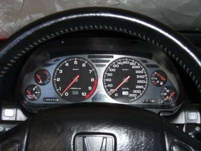
Cluster needle removal

dont be surprised when the needle doesnt move at all that mean you broke the tiny Hair or a wire that send the signal.

buying a replacment isnt cheap

at least you cant say you were never warned.
 
dont be surprised when the needle doesnt move at all that mean you broke the tiny Hair or a wire that send the signal.

buying a replacment isnt cheap

at least you cant say you were never warned.

I assume your referring this to another member lol

The tiny copper "eddy current" wires, are usually broken because someone over torques one or more of the 3 bolts that hold the gauge in place.

The "polarity poles" are in-cased in the white plastic I mentioned earlier, the bottom of these polarity poles are female threaded for the bolts to secure the gauge to the PCB board, the top of the pole sticks out and this is where the eddy current wires are soldered too, [3 in total]

What happens is, when the bolt is over torqued, it spins the polarity pole around inside the white casing, this in turn winds the eddy current wire round and then it snaps.
 
Has anyone got a wiring diagram for a 2002 cluster ? The updated manual is hopeless, I got a wicked test bed set up here to calibrate on the bench to the n'th degree, however I'm not sure which pin the speed sensor is to pulse ? my 91 manual is totally wrong .

Not looking for a schematics, that impossible, just interconnections.

BTW I have the time to reverse engineer these, do a detail schematic and modifications. Long term goal is to convert any cluster to any KPH or MPH . Will take some months but I'm confident .

any help appreciated :)
 
Last edited:
Having some real fun with this! I can't thing of a better project ATM, combines my love for the NSX and Electronic Engineering
:biggrin: I now have all the data I need to calibrate any speedo and modify any cluster to whatever I like with surgical precision .

BTW the needle I pulled out pictured earlier the post is back in and calibrated to within +/- 1 KPH

I'm scratching my head as to why the RPM pulse is 110V Peek to peek and the Speedo is only a standard TTL 5v Weird ??

DSCF0032.jpg
 
VERY INTERESTING!
Can you give us the relation you found of the speedo pulse/wheel rotation? Is is like a pulse every wheel/driveshaft rotation or something else? What type of pulse is that, can you show us the graph?

With 245/40/17 tyre, every wheel rotation= 1972.292 mm
at 100km/h you have 14.08 rotation/second = 14,08Hz, is that what you found ??
You could even calibrate the speedo depending on the wheel size, as I have seen many highly mod NSX with larger wheels :eek:

I suppose 5v won't be enough to trigger the spark plug igniter, this is why you need around 110v there, while the small speedo signal sender works with a much lower voltage
 
When I do this, I don't need any of that equipment to recalabrate. If the needle is pulled correctly, it goes back in at zero and doesn't require much to adjust, and on 2, it didn't require anything.

But good to see you have found an alternative solution.
 
Oh yeah the tach is derived from the igniter , must be attenuated in the cluster, a bit oddball .

The pulse is basic pulse width modulated square wave, and I think it's linear, not Lograthmic but some other function I havn't done the maths on it yet, early days . Not willing to share Frequencies just yet until I collate everything. The speed sensor get its pulse from the final gears as such it is very low frequency. Once I've built my mod circuitry I would definately be able to calibrate based on wheel size and rotational velocity. Again more maths. I'm basing all my data on factory tyres for a 91 as a benchmark and so far the service manual spec for 60kph in RPM is very wrong . Also I need as much info as possible on different year model pinouts.

Doing some more testing tomorrow , I want every frequency increment from 1 to 280 kph , should be fun . maybe better get on a dyno hey !! :biggrin:

My goal is if someone has a 180kph cluster , you send it to me, give me wheel diameter and I can send it back with a calibrated stock replica 280KPH or MPH as need be .

at 100km/h you have 14.08 rotation/second = 14,08Hz, is that what you found

No Suprisingly !! there must be a multiplier in the sensor or something ??? Really odd stuff ! EDIT , It will be because the hall sensor comes from a gear up and won't directly corelate to wheel rotation Frequency .

This is all the pulse looks like, This is 100kph , I think from the function generator, not very exciting .

IMG_0421.jpg


VERY INTERESTING!
Can you give us the relation you found of the speedo pulse/wheel rotation? Is is like a pulse every wheel/driveshaft rotation or something else? What type of pulse is that, can you show us the graph?

With 245/40/17 tyre, every wheel rotation= 1972.292 mm
at 100km/h you have 14.08 rotation/second = 14,08Hz, is that what you found ??
You could even calibrate the speedo depending on the wheel size, as I have seen many highly mod NSX with larger wheels :eek:

I suppose 5v won't be enough to trigger the spark plug igniter, this is why you need around 110v there, while the small speedo signal sender works with a much lower voltage
 
Last edited:
yikes I thought I was the only one with that oscilloscope LOL

whats worse is I have that same model LOL

us tech guys are to funny
 
The distance covered per tyre rotation depends on tyre size and even with the same tyre spec (such as 245/40/17), the actual tyre diameter differs from one manufacture to another.

Therefore, you don’t calibrate the speedo against the tyre size.

In fact, in order to eliminate the variation, the VSS pulse is defined in the JIS.

  • For 4 wheels car, the VSS must be at 637rpm at 60kph.
  • The number of pulse generated by 1 rotation of VSS must be 4, 8, 16, 20 or 25.
Honda uses 4 pulses per VSS rotation. Please note that this is NOT per tyre rotation because tyre size will change the number of pulse generated.


JIS defines that the input signal frequency to the speedo must meet the following equation.

H[Hz] = V[kph] x 4[pulse per vss rotation] x 637[rpm] / 60[sec] / 60[kph]


So, at 60kph, the VSS square wave has to be at 42.47Hz and this is what you need to use for calibrating the speedo because this frequency is the same regardless of the tyre size or the car models.


As mentioned above, JIS definition is based on VSS rotation and not per tyre rotation.

Therefore, the number of pulse generated per tyre rotation will depend on the tyre size.

Presuming that you have 245/40/17 tyre at the rear, the circumference is 1972.3mm depending on the manufacture.

Therefore, at 60kph with this tyre size, it is at 8.45 rotation per second.

At 60kph, VSS is at 42.47 pulses per second [Hz].

So, 42.47[pulse per second] / 8.45[rotaion per second] = 5.03

Therefore, you will see about 5 VSS pulses per TYRE rotation for this size.

Kaz


<!--[if gte mso 9]><xml> <w:LatentStyles DefLockedState="false" LatentStyleCount="156"> </w:LatentStyles> </xml><![endif]--><!--[if !mso]><object classid="clsid:38481807-CA0E-42D2-BF39-B33AF135CC4D" id=ieooui></object> <style> st1\:*{behavior:url(#ieooui) } </style> <![endif]--><!--[if gte mso 10]> <style> /* Style Definitions */ table.MsoNormalTable {mso-style-name:標準の表; mso-tstyle-rowband-size:0; mso-tstyle-colband-size:0; mso-style-noshow:yes; mso-style-parent:""; mso-padding-alt:0cm 5.4pt 0cm 5.4pt; mso-para-margin:0cm; mso-para-margin-bottom:.0001pt; mso-pagination:widow-orphan; font-size:10.0pt; font-family:"Times New Roman"; mso-fareast-font-family:"Times New Roman"; mso-ansi-language:#0400; mso-fareast-language:#0400; mso-bidi-language:#0400;} </style> <![endif]-->
 
Kaz-kzukNA1;1636302 [FONT=Verdana said:
H[Hz] = V[kph] x 4[pulse per vss rotation] x 637[rpm] / 60[sec] / 60[kph][/FONT]


So, at 60kph, the VSS square wave has to be at 42.47Hz and this is what you need to use for calibrating the speedo because this frequency is the same regardless of the tyre size or the car models.

That exactly the frequency I came up with,(well 42.5hz) However you will still need to compensate for different tyre diameters somewhere if the standard speedo calibration runs out of range !!
 
Ok , update time

I've had 100% success with this, I've just converted a 180 kph cluster to 280kph by changing only the gauge face . Lots of electronics and bench calibration, but I've nailed it .

So in conclusion, once I have the multiple layered polycarbonate screen printing down to an art, I can convert any NSX cluster to any scale or face colour one would desire, and calibrate on the bench with precision. can also do the Tacho on bench. Have to hit it with a 110v pp square though. which is a bit tricky.

Pics shows 71 ish HZ (100KPH)

IMG_0653.jpg


IMG_0654.jpg
 
Last edited:
So are you offering this service?

I will be, but don't want to get in trouble for advertising in a post . I will start a vendor page

The plan would be, send me your cluster and I modify to user specs, or an exchange basis

The biggest problem ATM is getting the Faces made up. They have to be laser cut Polycarbonate and have the orange transparency screen printed like a sandwich . I'm in discussion with manufacturers now.
 
Interesting. Glad to see some ETs here. Never used OScopes on cars but glad peeps found a use for them beyond work :p (spent a lil over a decade doing RF). I'll be checking progress here. I'm sure youll have options. The cluster is one of the most often looked at items on as a driver in a car and its fortunate for the community to see some customization action there. Thank you!
 
Interesting. Glad to see some ETs here. Never used OScopes on cars but glad peeps found a use for them beyond work :p (spent a lil over a decade doing RF). I'll be checking progress here. I'm sure youll have options. The cluster is one of the most often looked at items on as a driver in a car and its fortunate for the community to see some customization action there. Thank you!

Thanks, I really started this for myself as its near impossible to find oem 280kph clusters , but if I can keep the cost down enough help the nsx community out , why not do a heap of them .

I,m also on the hunt for cheap clusters of any type, there is a lot of 180kph clusters in Japan that would need doing .

I should add that obviously I can only calibrate to factory standards, unless I have very specific tyre diameter data.
 
Last edited:
So here's a question I have, as I am simply wanting to change the color of the amber light that is used for the display to a blue. I've started a DIY at http://www.nsxprime.com/forum/showthread.php/168013-LED-Speed-Gauge-Cluster-Build

I have my cluster out and the faces exposed, by removing one of the bulbs that sit behind the speedo and shining a pen/led light through, there's still an amber color in the numbers of the speedo, which would lead me to believe there's a film of sorts between the black face of the gauges and the plastic they sit behind.
Is this correct?
If so, is it possible to remove this amber film without having to pull the needle out or remove the entire face? By using a dimmable and colored LED in place of oem bulb, I'm hoping to change the color of the gauge display.
 
In UK and Ireland..... Speedo must show Dual display for legal purpose and to get it through the MOT tests every year....

So UK cars must show MPH and KPH.....
 
Back
Top