• Protip: Profile posts are public! Use Conversations to message other members privately. Everyone can see the content of a profile post.

LED Conversion with Hyperflash and Brake Lamp Failure Solution

Well the brake lights did not go so well. I thought I found the correct wire but after blowing several brake light fuses I decided that it was not meant to be for my NSX. Every other light but the rear brake lights are LEDs and the car looks great.

My car is a very early one and who’s to say if my wiring is different. I do have an extra fan in my engine bay.

Thank you for all of your assistance. The turn signals are perfect.
 
Last edited:
Sorry to revive this old thread. I'm trying to replace the turn signal relay with a modified version to resolve LED hyperflashing. But I have a 1993 JDM RHD. Anyone do this to a RHD and can guide me where the relay is located? It is NOT to the left of the steering column like LHD cars, nor is it mirrored and on the right side of the steering column and above where the footwell light would be. And it's also not in the left side footwell where it would exist in LHD cars. Can't seem to find anything on the interwebs of a RHD owner doing this mod. Thanks Prime!
 
I don't have a RHD, but I did the LHD version of this mod, and I want to see you get to the Promised Land!

It looks like the Flasher unit for the RHD drive is mounted on a small bracket near the ABS ECU & Cruise Control ECU "stack", which appears to be in the passenger footwell. The mounting bracket is unique to the RHD, so it will be different location than a LHD, but looks like its still on the left side of the car, more toward the center of the car than the LHD location. If you remove the glovebox, it might be easier to find (on a LHD, you have to remove the glove box to get to the ABS ECU).

Hopefully this helps, and apologies if it doesn't. I'm curious to solve the mystery... good luck!

Thanks. Yeah, I found the RHD parts diagram on the Amayama website, so it does appear to be in the left (passenger) footwell. But I took out the lower cover AND the glovebox, and still couldn't see it. The control stack takes up the entirety of what you can see. I tried to look up and around the control units but didn't see it. From the diagram, it almost looks like I'm going to need to remove all the control units to access where it is. So hoping someone has already done this with a RHD so I don't waste my time if it's not there.

I did see one comment on NSXCB from a RHD owner that said he found relay lying on the floor of his DRIVERS footwell, and wasn't sure what bracket it was supposed to be attached to. But that post is 7yrs old with no followup.
 

Attachments

  • NSX 1.jpg
    NSX 1.jpg
    80 KB · Views: 17
  • NSX 2.jpg
    NSX 2.jpg
    369.2 KB · Views: 13
It is a 6-cavity / 6-wire connector to the unit, so it should be a smaller harness branch feeding it. A small lighted mirror on a stick can be your friend here; that is my go-to when I don't want to remove anything but need additional visible angles.
 
Last edited:
Maybe a silly question, but can you remove the air duct at the top of the in-situ picture of your ECU stack? That might allow for additional sight lines toward the top of the ABS ECU. It is a 6-cavity / 6-wire connector to the unit, so it should be a smaller harness branch feeding it. A small lighted mirror on a stick can be your friend here; that is my go-to when I don't want to remove anything but need additional visible angles.

Yeah good idea about removing the air duct, I'll try that next time I go in there. After spending a few hours looking for this relay, I put the car back together so I could drive it while I did this research and tried again.
 
Yeah good idea about removing the air duct, I'll try that next time I go in there. After spending a few hours looking for this relay, I put the car back together so I could drive it while I did this research and tried again.
That is the true Eternal Sports Mind at work! Maybe I should follow your lead and put my interior back together too... spider that set up shop on my rear wheel might not like it though.
 
AL9nZEVEYFxGS5b58WeNeD96k8ikKknakU3NIS_cXQBOz9UE1sgHOduGtFS_axoUFAyKlr4Dh03QP7G4JNARsVBAo3aqyj-ytFa5G4-XJMkCPDcnOWGjcVwjNh4hrdYTEZfSqKQv3ZXd26ZnGy2BSDWHPnIHxA=w1080-h810-no

It's on the R-side (driver side for the RHD).
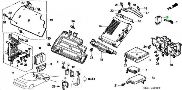
Probably missed the tiny square on the right in the parts diagram.

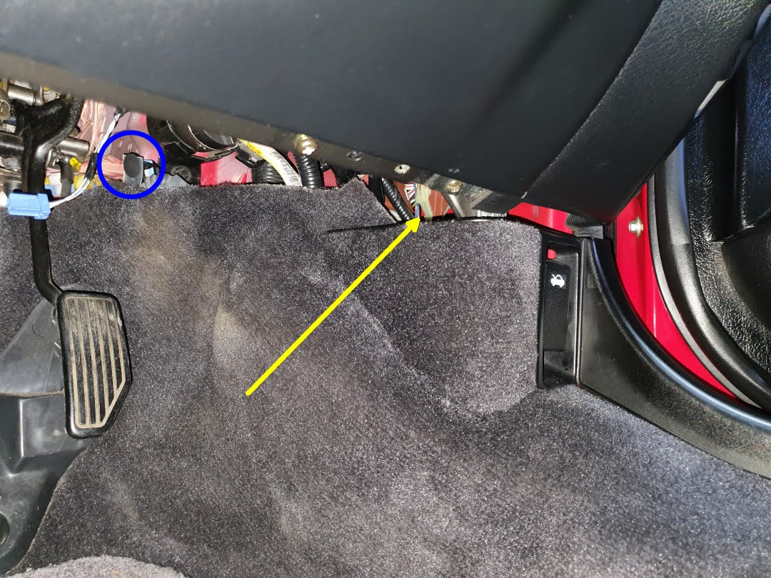
Remove the lower cover under the steering column.
2 x screw (blue).
Be careful not to lose the 2 x rubber cap (red).
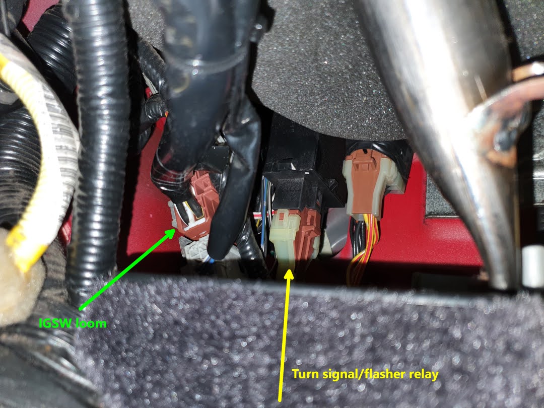
Disconnect 1 x blue connector from the foot well light.


AL9nZEUlFm4fmA_a9zgQOG-ggWb3SLfrD3ecrZ7j8kyPyR-zf-gZ_z1LZC1IH2nYpPEk5WGQ7tnc6iLtafU5CGG23DIrhIMoPSwBkZ6O4GLNUFDkIfDs5TOUuiqMJF5mWCr_OBAYUmed6dVKk0FZbENbqWboQQ=w1080-h810-no

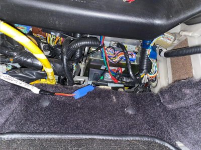
You can just about see the brown connector with custard sleeve for the flasher relay (yellow).
Remove 1 x fastener (blue) to peel off the carpet for better access.


AL9nZEXPIcqH9BB5h7Y7LoZ5R9c7y0_OCtVqEUjVYHsbm7rdqWtdATA7OZ0n01RLa5GurpJeFEgRbJ4yXdVnbkzf3nrJkLZPKaaS39XWDnPEfwz5k23K9xJKnM9AkiBTVKfi_0qCZJXeZRBhuv_Nimtn0We6rA=w1080-h810-no

The brown connector with the black square case.


If someone worked in the area in the past, could be tacked away somewhere else.

Move the car to quiet area.
Avoid other noise so don't run the engine.
Don't insert the IG key into IGSW cyl if you have the key reminder feature.

Activate the hazard lights and crawl into the driver foot well.

Listen for the clicking sound of the mechanical relay.

Once found the black case, try placing your finger on it.
You can actually feel the 'clicking'.


Never tried separating the relay from the bracket without removing extra parts.

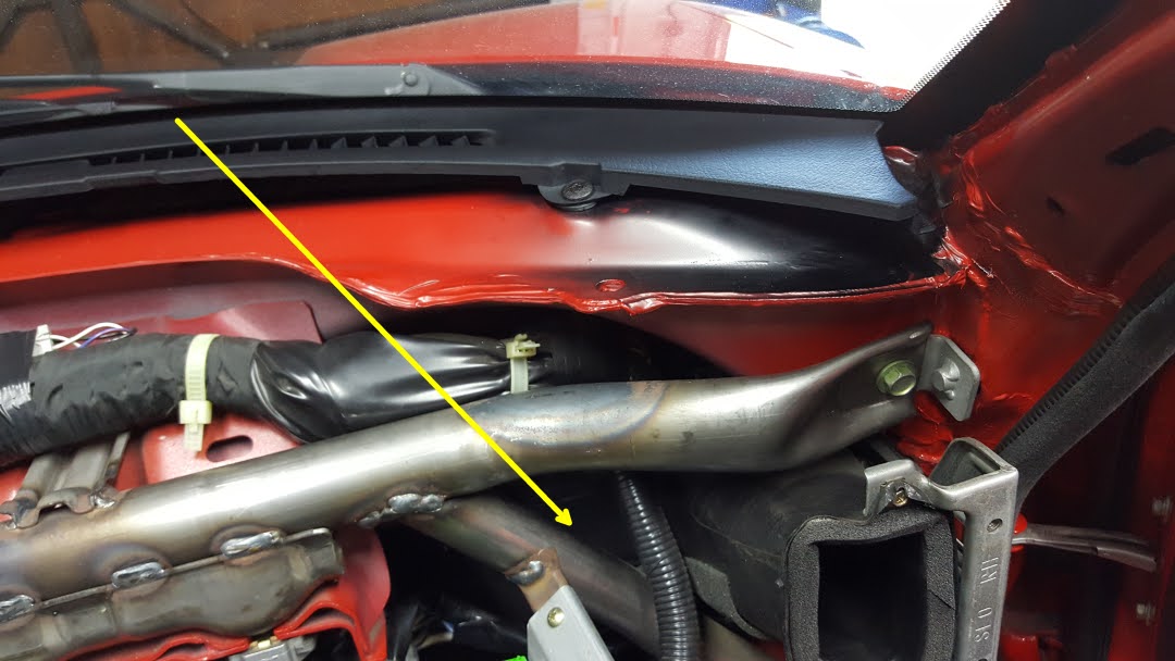
You could remove the side cowl that runs along the side sill/carpet.
It includes the plastic trim around the bonnet opener.
When the temperature is low, easily break the plastic parts on classic cars so be careful.
I normally warm up the cabin when working on plastic trim during the winter time.


AL9nZEULTm7yzs7KP0dSc3l8tVVAKDF3veKGNRxHz_7YP7s1VhRfU1SiAggypxXxy-ejCMpIDZrnw9Wyx3ABf2qDtZqND7sXC7bRnoeeXO0c3SmIA4wYYTl_9VxARffjAs44AFyw_hTn8ZI2-kuGrrbvkzLJAg=w1080-h608-no

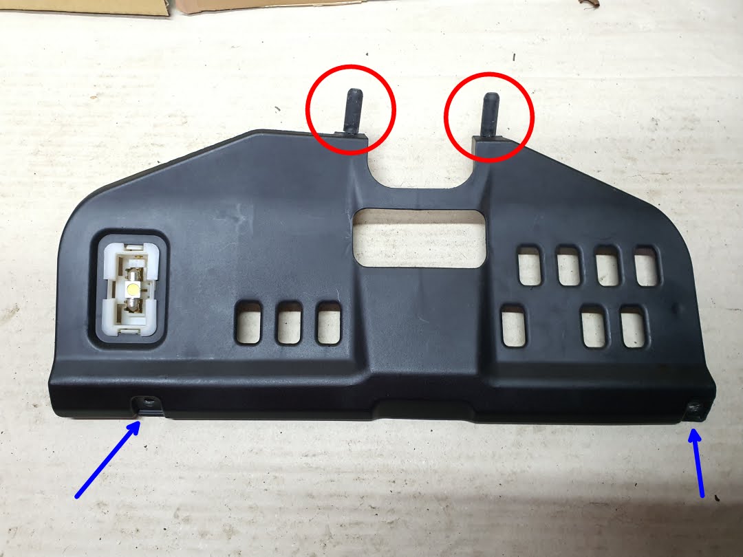
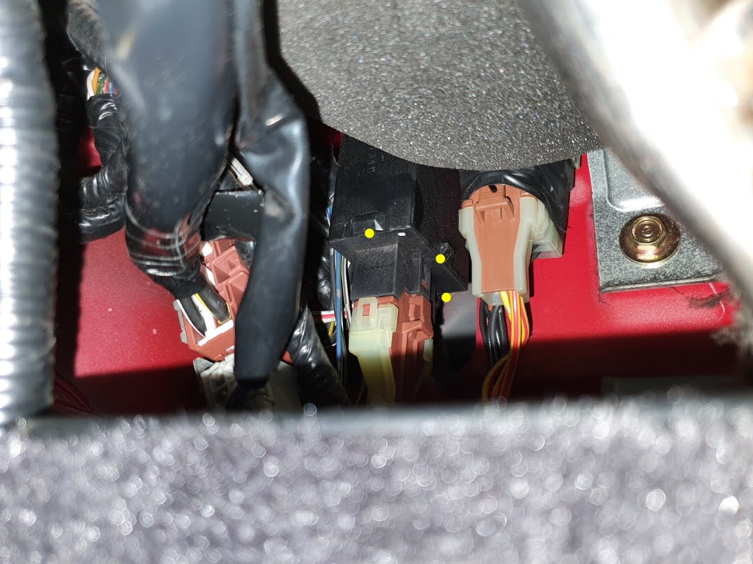
The majority of black relay housing/case is hidden/behind the a/c duct and the top section is locked with a horizontal bracket so not easy to take the relay out of the cabin.

With LHD model that has L-shaped bracket with lock at the top of relay, seems like you can use the 'twist' trick to apply enough leverage to unlock the bracket.
With RHD, the bracket is more of horizontal shape that don't know the same trick can be used.


AL9nZEXYUByxgnJij6yFFgHW9pKJoIiJoRK8LFm7MJCPPn-SbD5a4t_irYdcXmB3o5Bk8pUHJa9eM2SpaMan0jz47pgS9C697t5pV0-xHdkOApL58A4CoLOpMdEUDbifWWDqgAOpCYdFro0yTj-cWkNT2fVOlA=w1080-h810-no

Never tried the following so don't count on this.....

After disconnecting the connector to prevent the short circuit, may be you can run flat blade driver along the yellow dotted section to pry out the circuit board???
If same structure as the Main Relay, it should come out together with the bottom connector housing.
This will leave the bracket and the black housing as they are.

Again, never tried before so don't know it's possible or not.

Kaz
 
Last edited:
Absolutely brilliant! Thank you for all of that detail, Kaz! Great idea on applying mild heat; this should be attempted above 20C/70F.

I can add a view of the unit, at least. The connector receiver plastic will slide out with the PCB from the main housing. Here is a "bottom" view of the unit; one must apply force to pry the tabs open (shown within the yellow rectangles), but patience will win the day. If I recall correctly, only one needs to be freed and the other will have just enough freedom to pivot/slide out with less effort (focus on the side that is easier to reach). If you have a plastic trim removal tool, or a small pick, you can use it as an aid to hold "separation progress" on the long edges as you work with the screwdriver on the main tab(s). Patience will win over brute force!


IMG_20200711_164111689 - ZOOM.jpg

The PCB edges are contained by "C" channels in the main housing, and it will just slide out (no additional prying necessary once the bottom cover is free, just a straight pull toward the floor). With the connector/harness out of the way, there might be enough room to slide it out without removing the housing from its mounting bracket.

Then, the target is in full view:

IMG_20200711_164809998 - ZOOM.jpg

Just make sure to slide the modified PCB back into the housing in the correct orientation to fit into the "C" channels.
 
Thank you @Kaz-kzukNA1 for all the detailed pictures. I just got back from a fantastic weekend of driving in the mountains so will look for the relay this weekend.

Thanks @8kallday, I was already familiar with taking apart this relay since I purchased a spare and modified it (so that I could re-insert my unmodified relay if desired). I'm hoping Kaz is correct that I might be able to take apart the relay "in place" and just slide out the OEM circuit board and then I can slide in my modified board.
 

Attachments

  • IMG_6323[1].JPG
    IMG_6323[1].JPG
    528.3 KB · Views: 9
Thanks to @Kaz-kzukNA1 I finally located my RHD turn signal relay, it was tucked way up in the right-side kick panel of the right (driver) footwell. After disconnecting the harness, I spent about 3 minutes trying to wiggle the relay free and trying to feel how it was mounted, when it dawned on me that I was holding the modified relay and didn't need to actually remove the OEM relay for any reason. So connected the harness to my modified relay, tucked it behind the carpet, and voila! No more hyperflash! (but still need to modify the relay for a longer cycle for my particular LED set)

Thanks Prime for the help!
 
Can someone explain how the Brake Lamp failure bypass works? How does grounding the white/green wire make the sensor think everything is ok? The mod works perfectly, just curious "how" it works.
Sure. I think this is right.

The green highlight is the circuit for the brake light out sensor. If that is grounded, the warning stays off.

The orange highlight is the power to the brakelights. It goes though the brake light failure sensors, essentially each one has two internal relays that only operate if they see the correct (incandescent) current flowing through to each brake light bulb.

If all the brake lights are drawing the correct amount of current (the current used by an incandescent bulb that is not burned out), all four of the sensors close the circuit, and the green highlight path goes through each one of the four sensors (in series) and finally to ground.

LED bulbs use less current, so the brake light failure sensors don't see what they are expecting, and assume that a brake light bulb is burned out. Even replacing one normal bulb with an LED will trigger the alert, since the system is designed to monitor each brake light bulb individually.

To disable the brake light warning system, we connect the orange/white wire upstream of the brake light failure sensors directly to ground, so the system ALWAYS sees ground, so the warning will never go on. (Even if you remove all your brake light bulbs!)
.nsx brake circuit.jpg
 
Last edited:
The electrical service manual shows it fairly well. The brake lamp failure indicator illuminates if the sensor is not grounded via the orange/white wire. This wire is grounded by 4 reed switches in series, so all 4 reed switches need to to be closed or else the sensor will illuminate. Reed switches are basically current sensors. The trigger current through the brake light bulb also goes through a low resistance coil that triggers closing the "relay". When any incandescent bulb blows, no current goes thru that bulb (opening its attendant reed switch) and the connection to ground is broken, triggering the bulb-out indicator.

Most LED bulbs draw so little current that it is not enough to trigger the reed switches. The solution is to bypass all 4 reed switches and ground the sensor as shown. If it's bypassed and the indicator still illuminates, you've got bad capacitors in your dash (fire risk), call @Briank :

The additional challenge is that the wire colors change at C562 in the NSX as also shown in the electrical service manual, so you need to be sure which side of C562 you're tapping into. There are a couple other threads I've seen in the past that describe the bulb-out circuit as some sort of "balancing" circuit sensor, but that is incorrect, as shown in the electrical manual; 4 LED bulbs will be balanced but not trigger the reed switches, so the indicator comes on.
 
Last edited:
You can just add a jumper to two wires on connector C562.

 
Back
Top