• Protip: Profile posts are public! Use Conversations to message other members privately. Everyone can see the content of a profile post.

VVIS Project - Carbon clean up, screw security and "porting"

Joined
18 November 2010
Messages
1,057
Location
Pasadena, CA
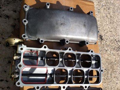
I had a spare intake manifold assembly laying around, so I thought I'd perform a complete "servicing" of the VVIS plate.

Here's the VVIS plate in "as is" form.
VVIS 1 - as is.jpg

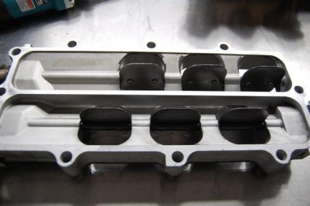
Here's the #2 plate (middle) upclose. Notice the gunk? This is off a car with about 54,000 miles.
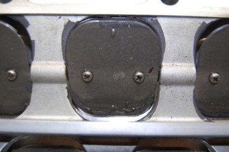
VVIS 2 - middle plate.jpg

Here's the #3 plate. Lots of gunk (arrow) there.
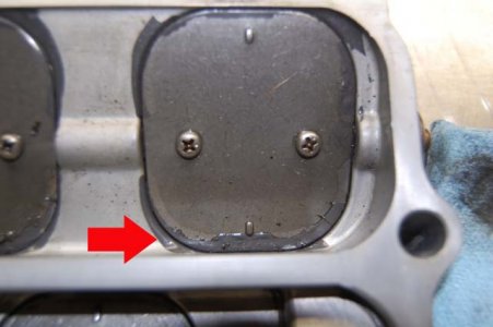
VVIS 3 - outer plate.jpg

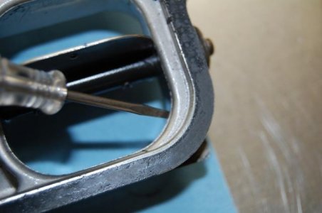
I simply took a small flathead screwdriver and simply chipped (or "chunked") away the gunk. Here are the "leftovers" after a cursory chunking session.
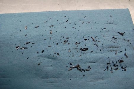
VVIS 4 -after Round 1 of cleaning.jpg

Here is the #3 plate after cleaning (looks better, doesn't it?):
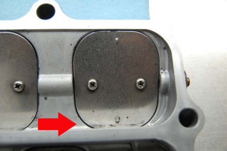
VVIS 5 - outer plate cleaned up.jpg

Now, I want to remove to the "ridges" that were leftover from (I'm assuming) the casting process. I'm not an engineering, but I'm assuming that those aren't good in the airflow-scheme of things:
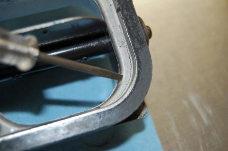
VVIS 6 - ridge over  before.jpg VVIS 7 - ridge under before.jpg

Using my Makita die grinder and a 180-grit cartridge roll, I cleaned everything up. The results:
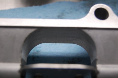
VVIS 8 - ridge after.jpg
(Smooth like a baby's butt).

Finally, I went ahead I applied Loctite Red (271) threadlocker to all my VVIS screws. In my case, I did NOT find any that were loose. Your results may vary.
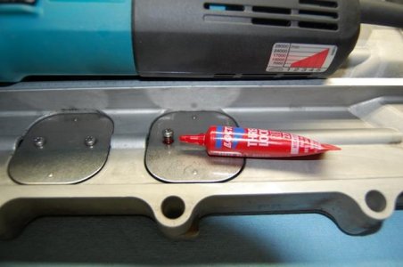
VVIS 9 - Loctite 271.jpg
 
Last edited:
Are you sure that it's really gunk? Isn't carbon build up black, oily and/or hard and brittle? I have seen a few VVIS's and they all consistently have it there. It looks to be some sort of extra sealant/cushion added there by the factory is my guess.
 
Last edited:
Are you sure that it's really gunk? Isn't carbon build up black, oily and/or hard and brittle? I have seen a few VVIS's and they all consistently have it there. It looks to be some sort of extra sealant/cushion added there by the factory is my guess.

That was a concern of mine at first, but when I chipped it off and inspected it, it broke down/crumbled up pretty easily. I think a sealant would have behaved differently.

In addition, doing a "against the backdrop of a light" test, there were plenty of tiny gaps in the "as is" VVIS.
 
Last edited:
I noticed it was brittle as well, but figured it was due to heat and age. Same thing with the gaps on the plates allowing light to pass through. I left it alone as I was thinking it was put there for a purpose only Honda knows.
 
Hummm... I wonder if I should take mines out and check mines? How do you know if something was to be wrong with the VVIS plate???
 
Loose bolts. Missing bolts. Pretty much it.

You would hear rattling noise on deceleration. Just do 4-5k and lift gas pedal.
 
Last edited:
I will have to do that next time I drive the NSX. What would happen if the screws were loose or missing? And harm to the engine???
 
If they were missing, you would've already known by now, as it would've been sucked into your engine. Which is why you need to check if they are loose :)
 
Well when loose it eventually comes off completely and then if you're lucky it ends up in the bottom of the manifold. If not then gets digested. There are quite few discussions here at prime about these butterfly valve screw get loose.
 
Wooo... I better check mines. Don't want that to happen. Thanks guys! Something for my to do to the NSX. Something to check and something g to do lol:biggrin:

- - - Updated - - -

I never took the VVIS plate out before anyone here have DIY instruction on how to remove it before I start. I'm sure I can figure it out better be easier and better if I have something to read about before start. Thanks in advance!

- - - Updated - - -

With nsxprime with all the updates and whatever they doing it's kinda hard now to search for what I'm looking. I use to search and always find what I was looking for but now it's like no result. Anyways, thanks in advance! :smile:
 
I think what people mistake for carbon buildup is actually gunk from the PCV valve over years of recirculating the crankcase fumes back into the throttlebody. Otherwise it would be sparkling clean since only intake air would pass through it. I have deleted my PCV a long time ago after cleaning my FILTHY TB. To this day that TB is still clean as new.
 
I think what people mistake for carbon buildup is actually gunk from the PCV valve over years of recirculating the crankcase fumes back into the throttlebody. Otherwise it would be sparkling clean since only intake air would pass through it. I have deleted my PCV a long time ago after cleaning my FILTHY TB. To this day that TB is still clean as new.

What you mean by deleted your PCV???
 
Absolutely. I have a small breather filter on each valve cover. Been like that for years. I don't like the fact that my crankcase fumes were being ingested into the intake/valves and cylinders. I feel it runs much cleaner with just air from the airbox not mixed with hot crankcase oily fumes. I have zero gunk in my TB for 2+ years now.
What you mean by deleted your PCV???
 
I had a spare intake manifold assembly laying around, so I thought I'd perform a complete "servicing" of the VVIS plate.

Here's the #3 plate. Lots of gunk (arrow) there.
View attachment 107798

I simply took a small flathead screwdriver and simply chipped (or "chunked") away the gunk. Here are the "leftovers" after a cursory chunking session.
View attachment 107799

lol, did you know that is not gunk. You just removed the sealhttp://www.nsxprime.com/forums/images/smilies/confused.gif
 
I don't think it's gunk. If you look at how nicely it's applied it looks like a seal. Mine didn't have it though.

I was planning to kill PCV too. For the same reasons davidf mentioned.
 
It’s the coating.

The product is called as Throttle Coat. You can find the same coating on other throttle bodies on other cars.

Not sure whether it was really required for the VVIS application because it was not required to create tight seal at the VVIS butterfly plate but it was applied.

It was also applied bit thick for some reason as normally, you only need thin coat.

I was worried about this thick coating becoming somewhat ‘ragged’ into bits and pieces and being swallowed into the engine but I was told that it’s mainly Molybdenum that won’t cause issues to the engine at this tiny amount.

There is a mechanical linkage between the two sides of the VVIS shafts so they operate simultaneously.
If you left the engine switched off over night or if you disconnect the #3 vacuum line to release the back pressure from the diaphragm, you can operate the VVIS and see its movement through the TH body by moving the linkage with your finger even without running the engine.

Kaz
 
I am sort of confused how this VVIS works. Below 4800rpm, the plates are closed and thus the intake chamber is smaller (only getting air from the top half of the intake manifold). However, above 4800rpm, the plates open up and introduces air from the whole intake chamber. The part I don't understand is, the bottom chamber is a closed area. How does air enter this chamber so that is exits thru the 6 VVIS plates? Am I missing something here? Wouldn't it be more effective if we cut and open up the front area of the VVIS?

IMG_07672.jpg
 
The idea behind the VVIS is that in the lower RPM range, there is enough volume of air "stored" in the upper plenum.

When the plates open, there is more volume of air for the engine to suck in. Whether or not proper velocities are maintained or achieved is data that most likely only Honda has.

As to your specific question of "how does air enter the (bottom) chamber?" - it really doesn't. It acts more like a "reserve" from which the engine can draw from.

All in all, the entire OEM intake manifold is most likely a giant compromise in packaging, given the design and space it occupies, as well as an insight into what Honda was experimenting with at the time in terms of variable-volume plenum'd intake manifolds.
 
I think the point of the VVIS is to have the intake pulses from one cylinder arrive at the next cylinder at the right time to push more air into it and to have the resonance of the intake manifold do the same.

When the VVIS valves are closed, the center wall of the intake manifold divides it into two separate plenums. Each bank of three cylinders breathes through its own plenum. When the VVIS valves are opened, the two plenums are joined via the lower chamber in the manifold. The two halves could have been joined by putting the VVIS valves directly into the dividing wall but that would have shortened the distance the pulse from one cylinder has to travel to get to a cylinder in the other bank. Joining the two plenums via a separate lower chamber lengthens the effective distance between them and changing the volume changes the resonant frequency.

If you look at the intake systems of modern Ferraris, they have similar systems. Separate intake plenums for each bank of cylinders that can be joined by opening valves when the engine computer says it will help with cylinder filling. And of course, the distances and volumes have to be calculated correctly for that to work.
 
If that is the case, I can see why the OEM VVIS doesn't work to its full potential. The OEM manifold sucks air from the top but the VVIS directs air downwards to the bottom chamber and then back up again.

If 4 of the 6 butterfly valves are "disabled" and only leaving the most inner 2 open, then we would optimize cylinders 2, 5, 3, and 6.
 
You know how you can create a tone by blowing across the top of a bottle and how the frequency of the tone changes based on how empty the bottle is, in other words, how much air is in there? That's how changing the volume of air changes the resonant frequency.

When you open a door at home, you hear noises in the next room much more clearly. The pulses – the sound waves – can make it to your ears much better.

Those are the two principles I believe Honda wanted to take advantage of with the VVIS system. As L_RAO mentioned, the air doesn't really flow into the bottom chamber. It's like an increased volume echo chamber / opening the door to the next room to better hear what's going on in there. At some revs that improves cylinder filling and at other revs, it doesn't. So sometimes the VVIS valves open and sometimes they are kept closed.

Ferrari use similar systems in their engines. In their technical description of the 430's intake manifold, they stated that it features two separate plenums, one for each bank of cylinders. A rotating drum, actuated pneumatically by the engine control unit, changes the "effective volume inside the two plenums to optimize the intake resonance characteristics and therefore maximise the torque curve throughout the rev range." They didn't say that it reduces the intake restriction or improves the flow or anything like that. It changes the resonance.

In the 458's manifold, Ferrari connect the two separate plenums together with three tubes, each of which has a valve in it. From the technical description of the 458: "The engine mapping provides four different configurations of the valves for optimum torque values at all revs." It sounds like a VVIS system except that the valves can open individually instead of all or none like in our cars.

I think the point of the VVIS system is to have sound waves - the resonant frequency of the manifold itself and the "pulses" reflecting off the backs of intake valves that have just closed - reach intake valves that are still open at the right time. Since the right time varies depending on how fast the engine is spinning, the intake manifold itself needs to have a variable configuration if it is to allow for those effects at various RPM instead of just at one particular engine speed. So I don't think that removing 2/3 of the plates in the VVIS system, leaving two of them in place to open and close as Honda's engineers intended, is likely to be an overall improvement.
 
Back
Top