• Protip: Profile posts are public! Use Conversations to message other members privately. Everyone can see the content of a profile post.

Down Under Trackday NSX

Hey Billy...…… if that was the case then would the argument be the same for a hot blown diffuser where the hot exhaust is routed through the diffuser into the flow of air ?

This diffuser area is over twice the area of the old diffuser and the coolers won't be taking up the whole diffuser area so we figured that even if it doesn't work as effectively it would only hopefully disturb the flow in one area of the diffuser and not the whole thing...…… maybe some more in depth assessment might be worth doing before we get too far along !!!

A fair chunk of the diffusers ability to create that underbody lower pressure comes from the channels either side of the centre as well and they're separated from anything we're doing in the centre...….

Thanks for the feedback mate...…..always open to comments as we're no Adrian Newey :)
 
Last edited:
It will probably render the diffuser useless as the low pressure area it is trying to create will be eliminated from the air being pulled through the intercooler. Diffusers are very finicky and rely on laminar flow to stay attached to the upper roof without separating/stalling, to create a low pressure area.

Billy, you should rethink your understanding of this setup. By removing air from the expanding wall of the diffuser, the intercooler configuration will tend to benefit the diffuser. As my brother put it: "boundary layer suction through a porous wall can be quite effective, to reduce boundary layer height and in turn allowing the flow to be worked harder." (Also of note, the flow in a diffuser is not laminar.)

The intercooler is not eliminating a low-pressure area in the diffuser because it's not blowing air into the diffuser. Rather, it is extracting air from the diffuser and therefore reducing the pressure in the diffuser. Without sufficient extraction through the intercooler, the roughness it puts on the diffuser surface could be an issue but hopefully the intercooler will pull enough flow such that the roughness isn't an issue.

The question here seems to be whether Fraser can pull enough flow through the intercooler. It doesn't have static pressure driving flow, as do most intercooler configurations, so it's all up to the fan. Hopefully you can connect the fan with a plenum sealed to the coolers, to make sure you get maximum flow (suction over the entire surface of the coolers). Also, try to make the diffuser-cooler transitions as smooth as possible.

I'll look forward to seeing your results.
 
Hey Billy...…… if that was the case then would the argument be the same for a hot blown diffuser where the hot exhaust is routed through the diffuser into the flow of air ?

This diffuser area is over twice the area of the old diffuser and the coolers won't be taking up the whole diffuser area so we figured that even if it doesn't work as effectively it would only hopefully disturb the flow in one area of the diffuser and not the whole thing...…… maybe some more in depth assessment might be worth doing before we get too far along !!!

A fair chunk of the diffusers ability to create that underbody lower pressure comes from the channels either side of the centre as well and they're separated from anything we're doing in the centre...….

Thanks for the feedback mate...…..always open to comments as we're no Adrian Newey :)
Blown diffusers take high velocity and high energy airflow from the exhaust to energize the boundary layer in the roof of the diffuser, adding high velocity flow to further reduce the pressure in the diffuser.

You're not going to get anywhere near that velocity from fans, or ducting to the top of the intercooler, though the cooler, and into the diffuser to create this benefit.

Yes the fenced off side channels will probably be the only thing that creates any amount of downforce in your setup.

Billy, you should rethink your understanding of this setup. By removing air from the expanding wall of the diffuser, the intercooler configuration will tend to benefit the diffuser. As my brother put it: "boundary layer suction through a porous wall can be quite effective, to reduce boundary layer height and in turn allowing the flow to be worked harder." (Also of note, the flow in a diffuser is not laminar.)

The intercooler is not eliminating a low-pressure area in the diffuser because it's not blowing air into the diffuser. Rather, it is extracting air from the diffuser and therefore reducing the pressure in the diffuser. Without sufficient extraction through the intercooler, the roughness it puts on the diffuser surface could be an issue but hopefully the intercooler will pull enough flow such that the roughness isn't an issue.

The question here seems to be whether Fraser can pull enough flow through the intercooler. It doesn't have static pressure driving flow, as do most intercooler configurations, so it's all up to the fan. Hopefully you can connect the fan with a plenum sealed to the coolers, to make sure you get maximum flow (suction over the entire surface of the coolers). Also, try to make the diffuser-cooler transitions as smooth as possible.

I'll look forward to seeing your results.
Yes it is. You should re-read his original plan (or any of his posts):


At the top of the coolers shown below, Zac is going to make a composite part that will seal off the top apart from a feed from the outside of the car so cold air from the side of the car will be funnelled down a flexi pipe to the intercoolers. In between the side of the car and the intake into the cooler we are fitting a large flow electric fan so there is constant airflow regardless of whether the car is moving or not. The fan is rated to just over 750 square metres per hour, so that is approx. 25 square centimetres per second which doesn't sound like much but it's a reasonable amount when you take into consideration that there will also be more flow once the car is actually moving with the pressure from the diffuser.
Hey Billy...…… if that was the case then would the argument be the same for a hot blown diffuser where the hot exhaust is routed through the diffuser into the flow of air ?
 
Last edited:
Oh goodness my bad. I recommend reversing the flow to extract air from the diffuser. :)
While there is merit to the theoretical idea of sucking air though through perforations (or possibly a heat exchanger if the fin & tubes don't cause unknown problems) to create a boundary layer suction, in reality, there are a lot of problems with this plan when putting it in practice:

-There is little to no information on how the fin & tubes of a heat exchanger will affect the boundary layer.
-The fan has to create a lower pressure than the low pressure in the diffuser for this idea to even work from a downforce standpoint.
-The more effective and powerful the diffuser is, the more powerful the fan must be to draw an even lower pressure (vacuum) to suck air though the intercooler. *Assuming the fan does not stall*
-The fan has to create a SIGNIFICANTLY lower pressure than the diffuser to pull any air though the intercooler to cool the air.


EVEN IF THIS IS POSSIBLE, the airflow though the intercooler core would be VERY LOW and thus, WILL NOT COOL ALL THAT MUCH. Heat exchangers rely on pressure differentials across the heat exchanger to create flow through the core and cool down the fluid (in this case, the hot charge air from the engine).

The idea of trying to cool hot charge air of an intercooler by means of pulling air though a cooler from a lower than ambient source (diffuser) is a highly flawwed idea and will likely not see any cooling. I would still STRONGLY recommend ditching both ideas of which direction to have the air flow go though the intercooler in this design.
 
Hmmmm yes I see your point Billy...……… thanks very much for that...…… something more to think about...………..

Our thinking at the moment is that the new diffuser is a massive improvement on the current one, so even if the efficiency isn't great, it should still be an improvement over the current, I guess just not as good as it could be...……..

We may have to try and see if we can calculate what kind of loss we would be likely to see by doing things this way...….. I do have access to some CFD stuff, but it's time consuming to setup and it's a bit over my head in certain areas...….. If we find it's not working we still have a plan B which would be to swap out the air-air coolers for an air to water cooler in the same position and then make a new diffuser without the cutout so we're back to "normal" setup without any re-engineering.

I really do appreciate all and every input from other members, especially you Billy so thanks very much, I'm going to do some more thinking...… :D
 
Last edited:
Our thinking at the moment is that the new diffuser is a massive improvement on the current one, so even if the efficiency isn't great, it should still be an improvement over the current, I guess just not as good as it could be...……..
Without trying to sound pessimistic or mean, the (objective) reality is that the taitech diffuser is not very powerful, and the likeliness of the whole center of your diffuser being ineffective will leave the sides also, not very powerful. So I would guess that you won't see much of a difference over the taitech, and generally not much of a benefit over no diffuser.


We may have to try and see if we can calculate what kind of loss we would be likely to see by doing things this way...….. I do have access to some CFD stuff, but it's time consuming to setup and it's a bit over my head in certain areas...….. If we find it's not working we still have a plan B which would be to swap out the air-air coolers for an air to water cooler in the same position and then make a new diffuser without the cutout so we're back to "normal" setup without any re-engineering.

I really do appreciate all and every input from other members, especially you Billy so thanks very much, I'm going to do some more thinking...… :D
Unless you can take your car to a wind tunnel, i've seen so many pie-in-the-sky CFD calculations completely out in left-field, even teams in F1, NASCAR, and Prototype racing (until wind tunnel data helps put them in the ballpark). CFD needs constant checks and balances with real-world wind tunnel data to actually be beneficial and accurate despite what others will say.

Even the highest levels of time attack cars who have 'world-class' CFD behind them, are drawn to goofy caricatures of cars that the math tells them to do so, but then you'll see a far less extreme looking car with proper aerodynamics turn faster lap times. I've also driven many CFD-only developed aero devices that 'mathematically' create X amount more downforce, but in almost all cases, the parts were no where near what the calculations said.

I'm all for trying new things, testing, and pushing the envelope. However even with unlimited resources, wind tunnel time, and CFD; you have a big uphill battle to try to make that design work and there's a reason why no one does it. I would recommend saving a lot of time and money by just going to air to water.
 
Last edited:
Thanks Billy...……… always useful as always :)

I'm going to drop you a PM about another subject, but thanks again for the advice. I totally hear you on CFD...…. even wind tunnels you hear about teams talking about how their wind tunnel work doesn't seem to relate to what they're seeing on track so I totally get what you're saying there...….
My comments of wind tunnel validation should have the disclaimer *rolling-road*. These tunnels are insanely expensive and most people use tunnels with a fixed floor or at best, a rolling belt under the car, but not the tires. The majority of tunnels are this way and yes, they still don't correlate properly with real world results that you get on track or a rolling road tunnel.

Most CFD is pie in the sky until it's cross-checked with a rolling road tunnel.
 
Although it only seems like a little bit of progress it's actually been a major to get this stage done. I've been distracted with other things and this stuff required some major input from Zac as always when it comes to the composite stuff !!

I had been doing some hours here and there over the last few months getting the molds ready for use, cleaning, waxing etc etc and then we needed to get some clear gelcoat sprayed on and so that's where things stalled as poor Zac managed to break his arm and so wasn't able to work for quite a while and then he was flat out just catching up, but we finally got there and then we were able to lay up the first layer of carbon. I'm going to post pics of most of the stages even though some might be over it if you've followed the whole build I just thought it was worth posting them so others don't have to go back so far.


Next was a layer of Kevlar to help prevent impact from underneath cracking the guard. Then a layer of extra carbon material around the outer edges to add some stiffness.


Next was peel ply and mesh to help the resin flow.


You can see above there was quite a bit more setup to be done such as adding some spiral tube around the outside of the mold to help the vacuum flow properly to help resin..……...time consuming, also needed to make sure there wasn't any shape edges on the bolts holding the mold together in case it punctured the bag......…….all critical to getting a good part when using resin infusion.

Next stage was to make up a vacuum bag to seal the parts in.


Get each part into the bags and make sure there's enough slack in all the right places to help it force all the materials into the corners etc. Again quite time consuming (approx. 1 hour per part to get it setup)


Last part of the process is to let the vacuum pull the resin through the parts. You can see the difference in colour between this photo and the last as the resin has flowed in.


And after about 2 hours each to de-mold the parts are out. Not trimmed yet, but they look great...……..very happy. Super light......just under 1kg each.


Massive thanks to Jason and Zac from Carboglass for their help with this whole process...….
 
Well it's a very funny time around the world right now so I wanted to start off by saying that I hope everyone is safe and trying to help the world get back to normal as soon as possible.

I'm not sure what the story is in your part of the world, but here in New Zealand we're on a full lockdown to try and get ahead of the Covid-19 virus. That means our borders are closed so no one in or out of the country, no travel between regions via road, air or any other method and you're basically required to stay in your house and not to get close to anyone else outside of your own household so all pretty serious stuff, but I think the right thing to do to try nail this thing in our country at least !

We're locked down for 4 weeks and so ideally I would be working on the car during this time, but unfortunately a few days before our lockdown I was taken to hospital with a kidney issue I'm recovering from now and have another operation next week to hopefully get me back on the mend so I've not been able to put any time into the NSX, but wanted to share some of the recent work we've been doing to get our car back on track but with it's new J32A2 twin turbo engine combo and new aero.

Part of the engine change also pushed me along to re-do the entire engine loom using the same mil-spec components we used for our FZ12 project. The biggest headache when removing the engine was the old wiring loom didn't have bulkhead connectors so it meant removing all the plugs from the engine or the ECU side which was a nightmare so I wanted to put bulkhead connectors on the car anyhow, so that combined with needing to add sensors for traction control, more wires for intercooler temps, boost etc that we didnt' have before meant it just made sense to start from scratch.


There's still some more work to be done from inside the car to the ECU but hopefully that will be quite quick to get done once the lockdown is over.


Next job was to get the new front guard and bonnet mounted. It's been some time in the making so it felt good to finally get it on the car and I'm really happy with the results. We still need to add some mounting plates underneath which is why there are still some small wooden blocks on the outside but once we've bonded the plates underneath we will remove the wooden blocks and it'll be all finished.


Of course with the change to turbo also comes the challenges with getting enough air into and out of the engine. We wanted to bring air into the left side of the car where the OEM filter usually goes, but the fuel filler was getting in the way of having enough flow in for what we felt we needed, so Zac suggested a change of having the fuel filler coming out from the rear hatch instead which in turn free'd up the space we needed. I 3D printed a few examples before getting this right and I will eventually CNC this out of acrylic or maybe aluminium, but for now it proves the concept.


Next on the list is making what seems like an endless list of pipes for intake, intercoolers, exhaust etc........ but slowly working through these and just the exhaust side needs to be finished now, the intake and boost side are all done.


Also plugged up the extra pipes we don't need any more and cut off EGR valve mounts etc to tidy things up........


Also had to upgrade the fuel pumps. The existing Bosch 044 just wasn't going to cut it if we needed to run higher HP on E85 so we needed to go a step up with a couple of Aeromotive A1000 pumps.


This last part I'm really proud of. It's kinda a pet project as the old steering wheel worked OK, but the dangling cable (that pretty much every race car with buttons on the wheel has) has always bugged me. For our FZ12 project I came across a company in the UK who make a great bit of kit for steering wheels to make them wireless so that started my brain thinking about the one for the NSX considering we would now have a need for easy access to traction and boost control. I recently helped crew at the Bathurst 12hour GT event and saw some great steering wheel layouts and setups so that got my brain churning and this is the result. Some 3D printing again helped make it look really neat, but the plan will be to make a complete carbon one eventually.

Also looking to add paddles to the wheel once we go sequential........ I've left some wiring long enough so that we can easily switch from push buttons to paddles without any drama later.

Some people get worried about the battery running out, but it's good for 5 million + presses so should be fine for some time to come and starts flashing LED light when it's getting low so should never be an issue.


Well that's it for now. The J32A2 engines have had a full build (at what I think is a very reasonable overall price) with custom rods and pistons and with the 2 x Borg Warner EFR 6258 turbos the engines will be 800+ HP capable, although we probably plan to run most of the time around the 500WHP mark. I was due to get the engine back from the engine builders the day I got taken to hospital and then we went into lockdown so it's not been possible to get the engines yet, but once our lockdown is over I will be able to get it back and will post a seperate build section on the engines.
 
Last edited:
wow. this car is an absolute f*cking weapon!!:eek:
 
Instead of an April's fools post, this was an April's awesome post. Great stuff. Thanks for sharing.
 
Thanks for posting your updates. The work is meticulous and very interesting to follow the progress of this beast. Much luck in getting and staying healthy. We need more updates in the future!
 
Hey guys, thanks heaps for the comments. It indeed should be a weapon once it's all back together. Target weight ready to race (without driver) is 2310lb or 1050KG. We are pretty close to that now and we haven't done the doors yet, and we think there's a good 80lb to lose from the doors since we're looking to finally use our Plastics4Performance lexan windows as well to replace the glass ones.

As far as updates go.........I'm hoping that our lockdown will indeed finish in 3 weeks when it's planned (they might extend) I will be able to go and grab the engines (I've got 2 being built) and then we can start getting it all back together and get to my mate Chris from Prestige Tuning and Motorsport for a tune and then we can get it to the track to enjoy it ........

Hopefully later next week I will be able to get down to my workshop and get some more go forward on the internal ECU wiring and other stuff.
 
Truly an impressive build, and it was fun to be able to read so much of it at one time since I just stumbled upon it now. Very well done, and looking forward to seeing the turbocharged beast in all her glory!
 
Thanks Steve.

We're hopefully going to come out of our official level 4 lockdown next wednesday, so if that happens I should be able to get down to the workshop to get back onto this.......it's been hard not being able to get my new engine back from the builders and back in the car, but it all comes to those who wait I guess.

I'm going to do a seperate write up on what we've done with our J series just in case it's useful for others.
 
I hope everyone is doing well out there with this COVID headache trying it's best to hang around......

We finally came out of lockdown that allows me to travel to collect my finished engine so wanted to share.

Now before any eagle eyed people mentioned it........I've put the turbo's on back to front !!! LOL Was in a rush to get a picture as I had to go somewhere......but you get the idea hopefully from the pictures.


Alternator is missing too and a few other bits, but hopefully we'll get it put into the rear subframe sometime this week or next and then we can get it all reassembled. Then all that's needed will be to finish the wiring inside the car (the main loom is done from firewall to engine) and then finished the turbo to exhaust pipes (fairly easy work) and it should be ready to get started.

Winter is well and truly here now so no real rush from that perspective, but I'm really keen to get it done so I can get on with my FZ12 project as well as wanting to see what this can do on the dyno !
 
Well it took a good little while again, but eventually got some more updates to the car / engine.

Unfortunately there was a bit of a mixup with the engine builds (we're actually building 2 engines) and the pictures from the last post were engine #1 , but whilst we were about ready to put this engine back in the hole, we got a call to say there had been a mixup on engine #2 and it made them realise that the same mistake was made with engine #1 !!! so out came engine #1 to make way for engine #2 ............. still with me ? :)

Anyhow, all is well now with both engines as we hadn't started them so it was a good save !

It's the same old story that I was just going to put this back together with no dressing up since it is a race car after all, but I just couldn't do it and so I've done some tarting up of bits to make them look nicer with no benefits what so ever on a technical level !!

These are the main intake runners before and after masking, sand blasting and painting.


Whilst we were looking at the intake runners we realised that the Bosch Motorsport 1550cc injectors we were running weren't a nice fit so we machined up some press fit collars to go inside the OEM spot to reduce down and we are super happy with the result.........hard to tell that they're even in there if you didn't know.


Next step was to start planning and running all of the lines for oil and water to and from each turbo, fuel lines etc. Was really happy with how it came out. Big thanks to Reuben from R's Garage for the time getting all this done over the last few days.


Here's a little bit of a walkaround that makes it easier to see.
https://youtu.be/yPQXrZ3uk6g


And finally, it's back in the hole ......... pretty much just plug in the new loom and a few other bits and then get on with finishing off the fabrication of the exhaust to the muffler and it's ready for the dyno...... well, that makes it sound quick and easy which I doubt it will be, but we're a massive step closer !

 
Last edited:
OK so it's been a while but the car is finally back together and has been on the dyno.......... I'll get to that later, but just wanted to go through the stuff that we needed to do before the car was ready.

This whole upgrade process was meant to be quite straight forward, but as time went on, the scope just crept and crept and we have ended up re-engineering a large amount of the car. New engine, turbos, exhausts, oil system, entire wiring loom for whole car including the addition of a large amount of new sensors, diffuser, wing, wireless steering wheel etc etc the list goes on.

The first thing I needed to relocate and replumb was the oil cooler. Initially we had this on the right hand side vent just behind the door, but now we're using that to route air to the intercoolers so I needed to move it so that we could free up that vent and pathway. I decided (well there was pretty much no choice) to move it to the rear of the car. The oil coolers don't need as much direct air as something like an intercooler or radiator needs, but where I've located it, I think it will still get pretty good airflow anyhow.

So oil basically travels up from the engine to a remote oil filter housing just behind the driver (RHD), then leaves the filter and travels to the boot, throught the boot and out the back to the cooler. Then once it's been through the cooler it comes back into the boot. It then travels towards a one way valve before a T. That T feeds the Accusump with oil / pressure and so the one way valve is there to stop oil trying to force it's way back to the cooler if the Accusump opens and you get 80psi of oil pressure coming down the line..... Once it's left the T it goes back towards the engine and into the engine cleaned and cooled.


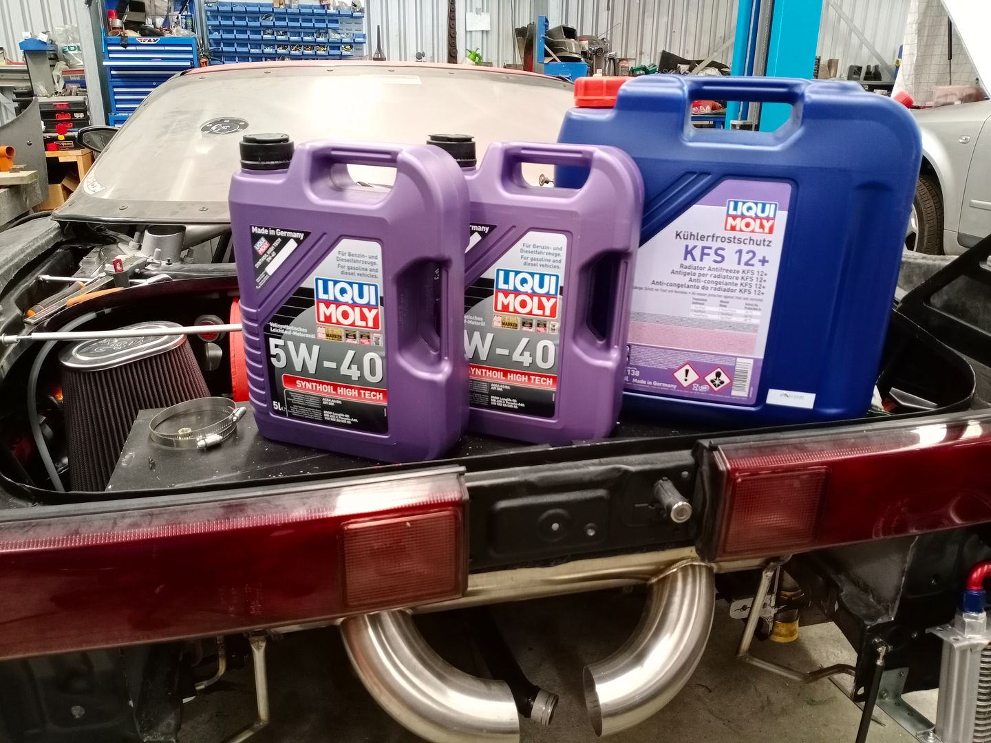
I've decided to make the change away from Motul to Liquimoly. Not because Motul hasn't performed well for us, but because I believe that Liquimoly is just that little bit better all around and they support some of my favourite racing series as well so I figure why not support them back. They take it all pretty seriously putting me in touch with a product engineer from Germany to discuss the car and use etc so they could recommend the right product.......very professional.


Next we needed to create some vents in the rear bumper that would not only allow some positive pressure out from behind the rear bumper, but also of course allow the cooler to work more effectively also. I only did the left side so it didn't look odd, but it's possible we might put a transmission cooler on that side also.


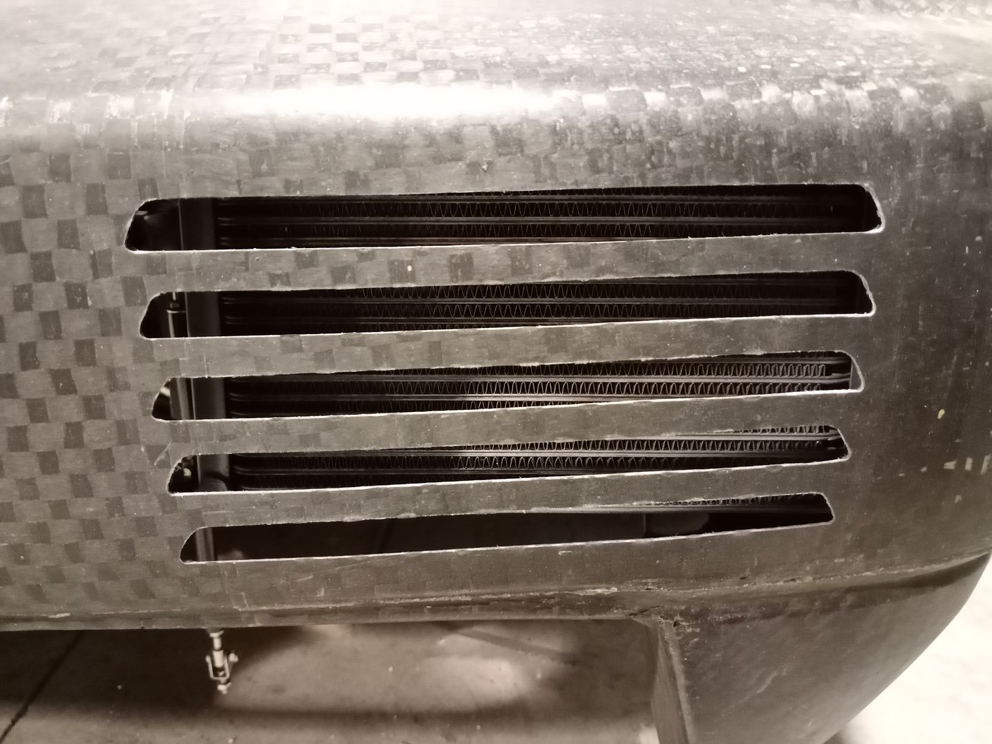
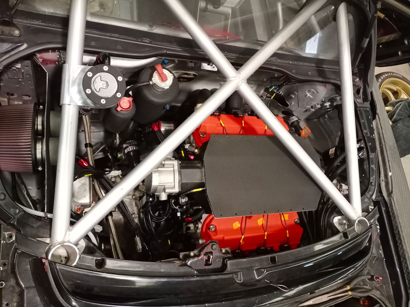
Next I needed to re-plumb the water system as well. I already had some of the tanks and I've taken a whole load of grief from my mates for my use of wrinkle paint, but I really like the finish and now I've started I can't stop as it looks weird if somethings not painted ! I prepped and covered the main header tank as well as an overflow tank. I had to re-mount them, and their final position is actually higher and more to the lef than shown here, but you get the idea.....


One of the parts I'm most happy with on the new build is the new fuel filler. This part came about again as part of the re-engineering process as we decided we wanted to pull more air from the usual side of the car, but with 2 large turbos to feed we needed to make the filter large and that meant we didn't have room to route the fuel filler out that side of the car, so Zac suggested we just route it up and out of the rear hatch and so I 3D printed quite a few versions of this to get it right and then we CNC'ed one out of aluminum and I think it looks amazing.


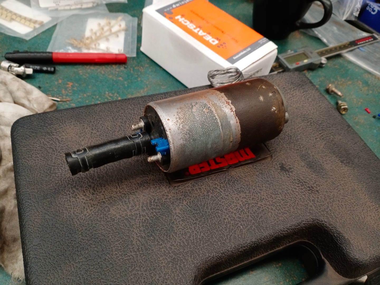
So after 30 years it seems like the factory fuel pump finally gave up the ghost. I think this was due to the fact that I emptied the tank so the pump sat in the air for a while, but it was jammed solid and wasn't going to move............. so we ended up replacing it with a DW400 pump from an Evo 8 I think it was. Was pretty much a perfect fit and my mate Reuben from R's Garage saved the day and dropped it down so whilst the tank was out it was an easy fix.


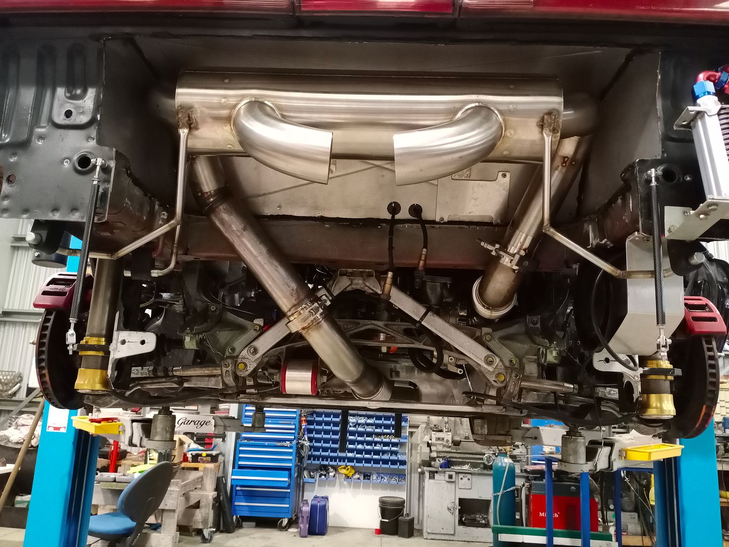
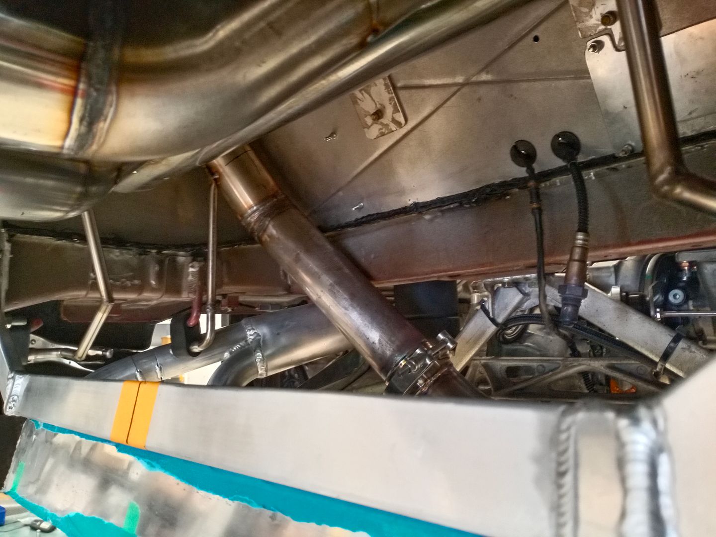
Next in line was the new exhaust. It was very tight from the front turbo to the front engine mount, but we finally made it through and then routed under the sump as normal.


We're also running a brand new muffler from Ace mufflers in Singapore. Originally it was made to fit a Toyota GT86, but I just hunted around for a muffler that was close to what I wanted. Amazingly I contacted Ace and asked if they could make me something similar, but not quite the same as their stock GT86 muffler and they said yes as they basically stopped about 90% of the way through the build as I didn't need the last 10%. Cost wise it was only a tiny bit more expensive even though it was essentially 'custom'.

Obviously the very simple exhaust hanger / mounts aren't something Ace did, that was me !! :) We will tidy those up once it's in it's final position.


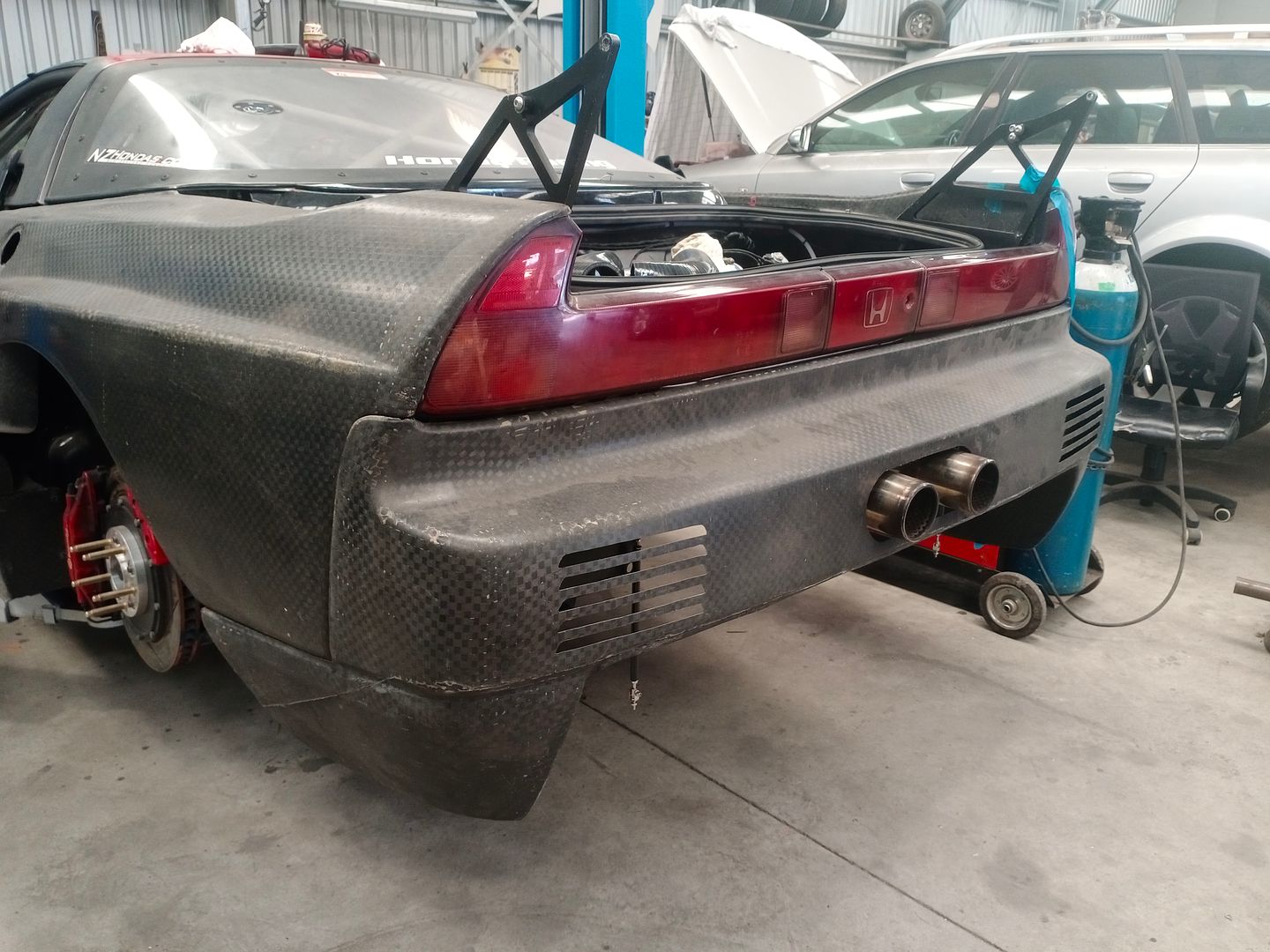
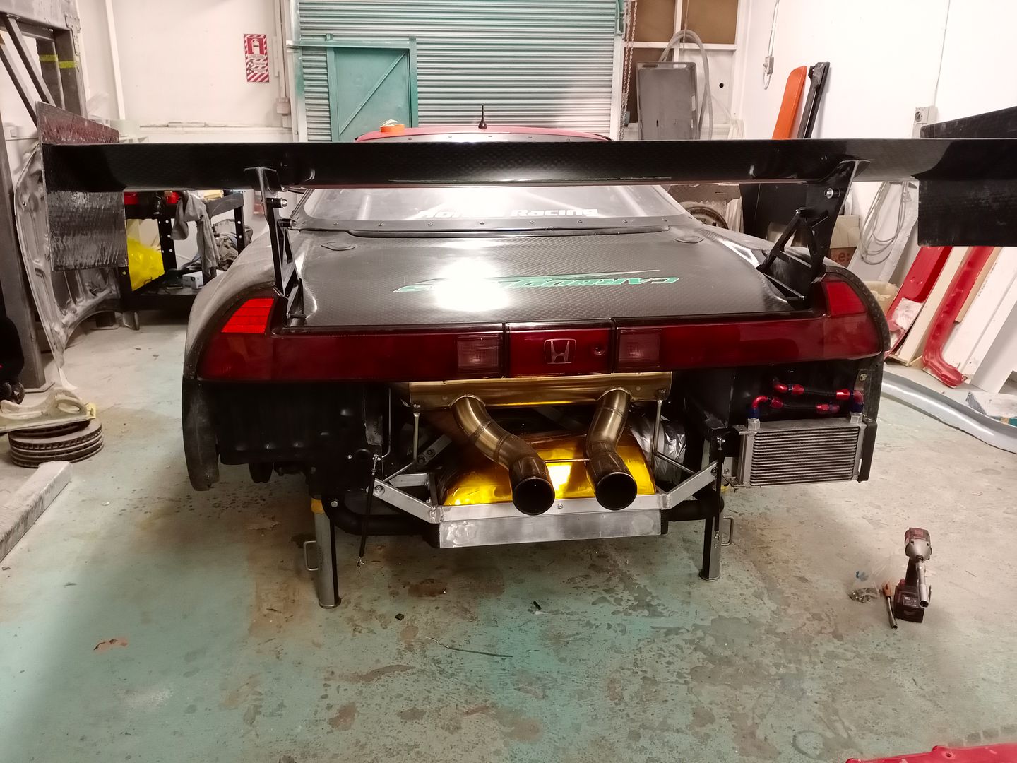
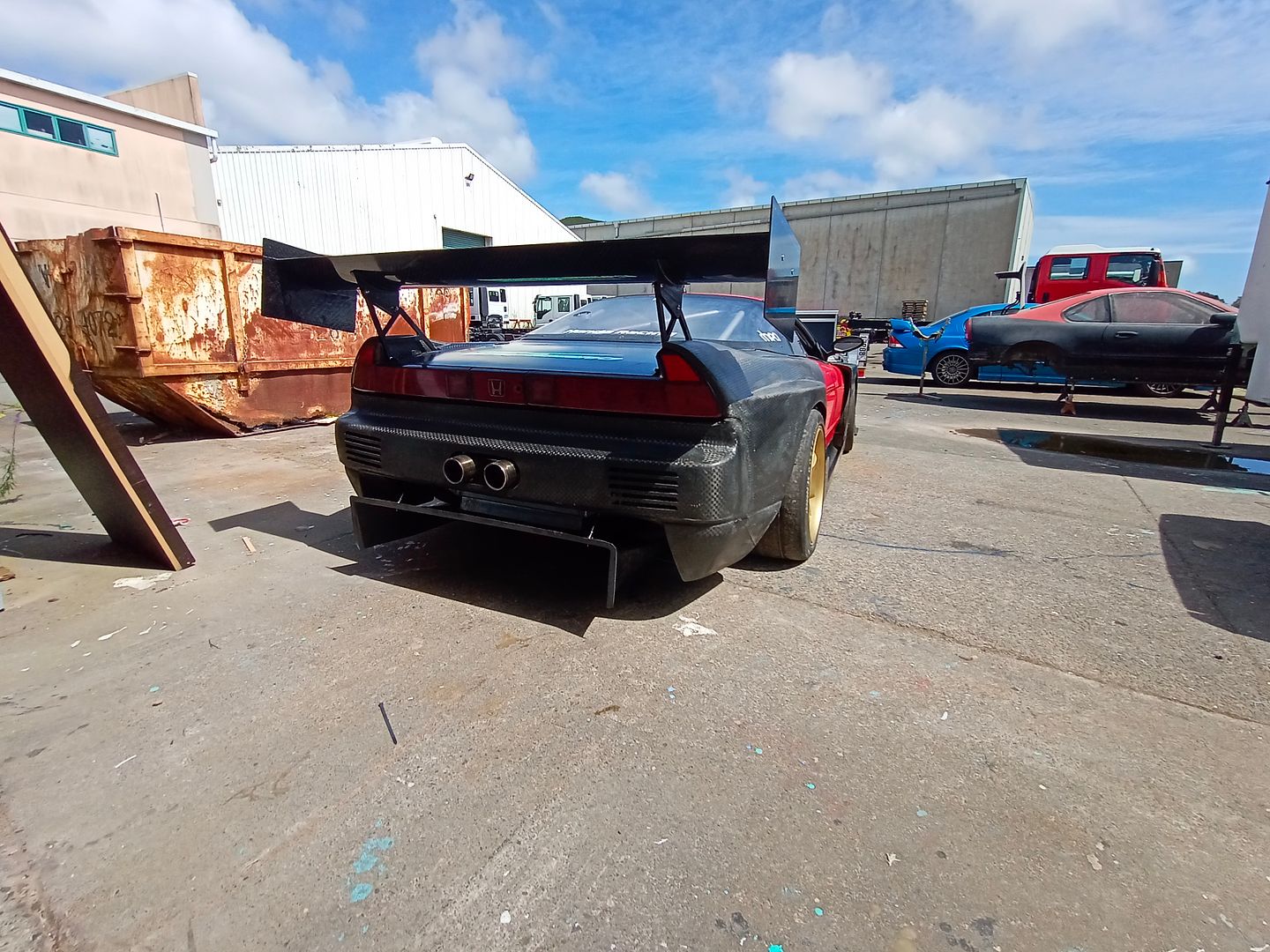
Once it was all finally mounted it was time to put the exhaust tips on and fit the rear bumper. We decided to stick the tips out more than before for a couple of reasons, but I'm really happy with the finished look.


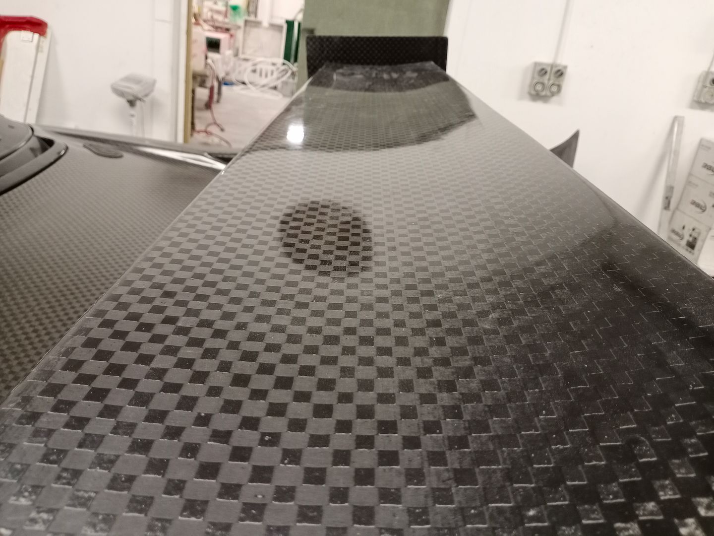
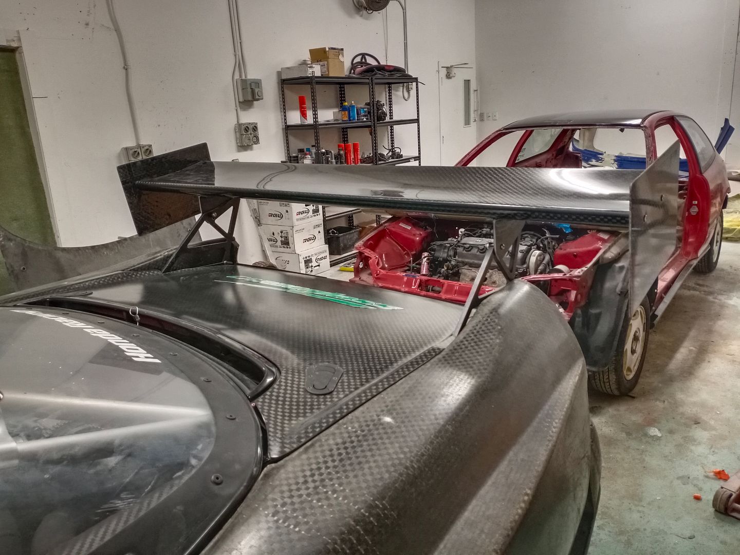
Although this isn't the final wing, it is quite different to the APR wing we had. Under Zac's guidance I prepped both sides of the mold ready for Zac to spray some clear gel coat. Then lay down some carbon, foam and bracing / glue. Then we're ready to bolt the 2 parts together and wait for the result.


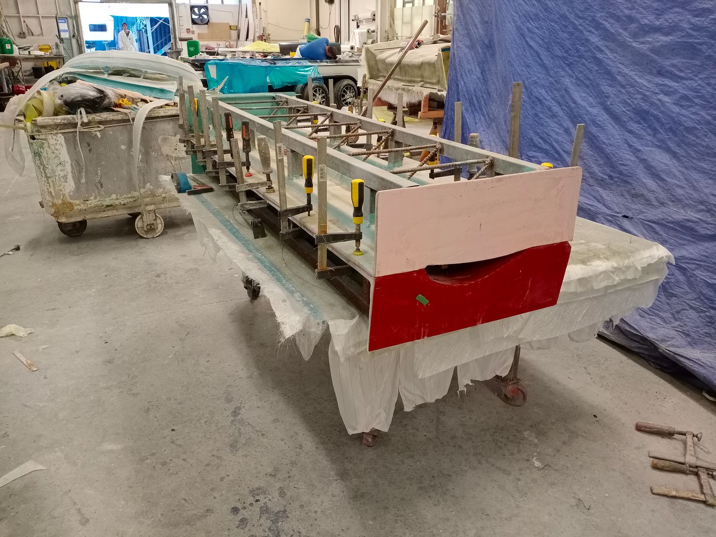
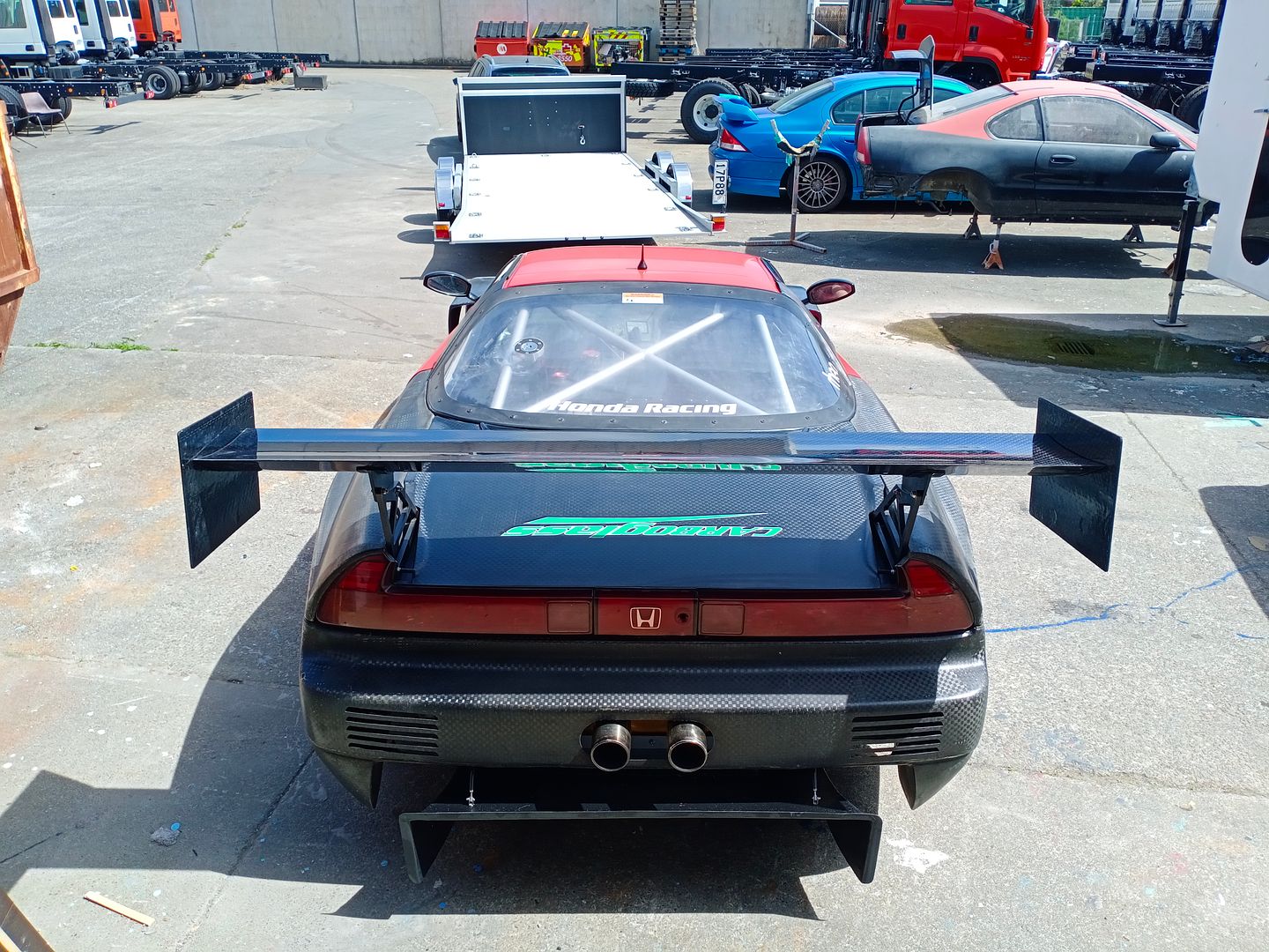
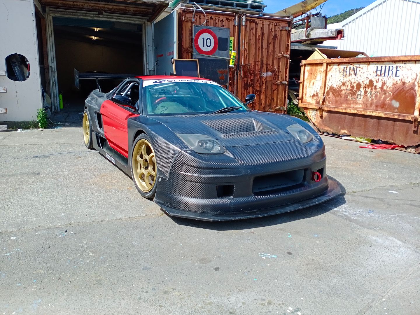
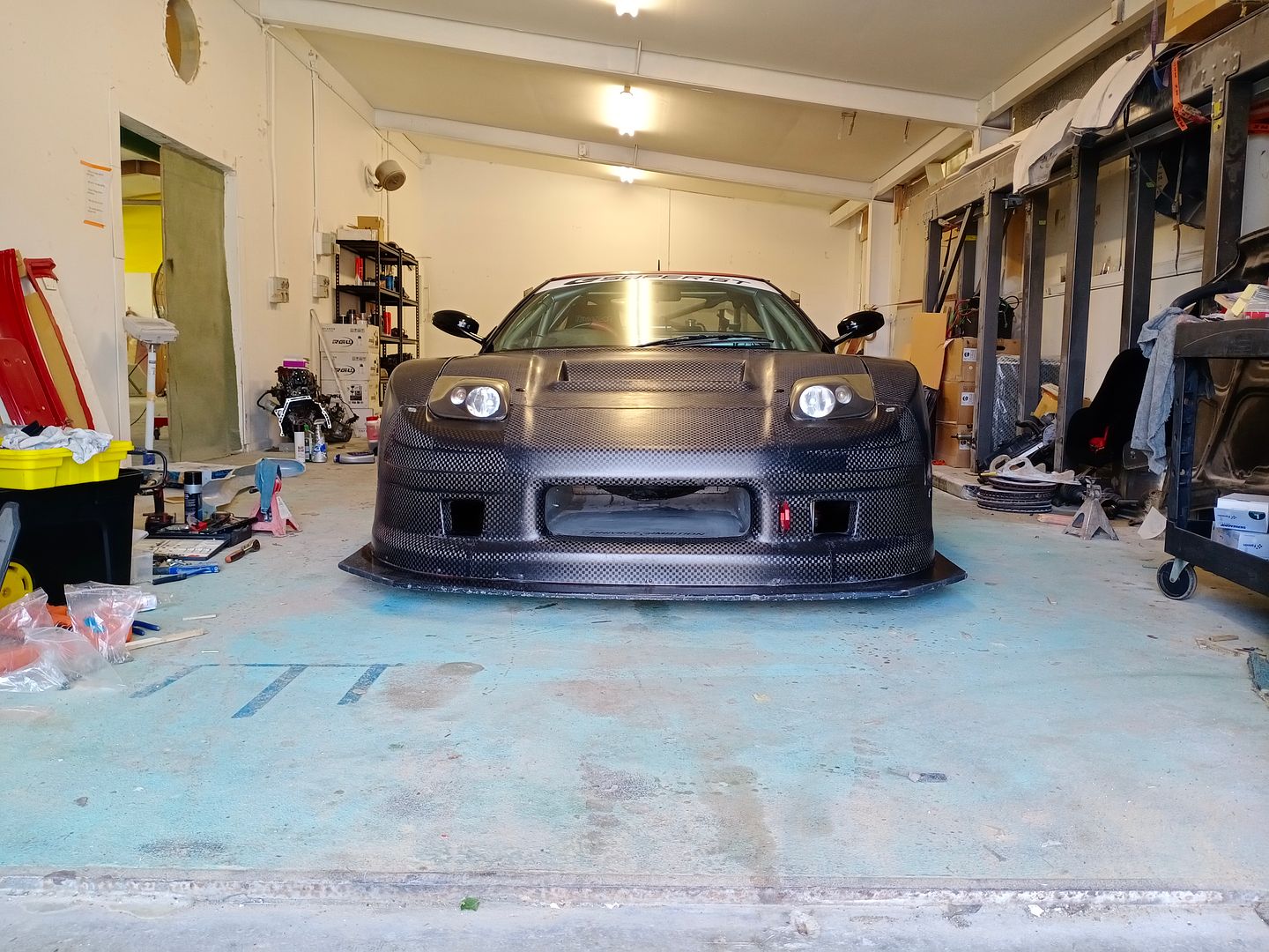
I hope you'll agree that the final result is awesome........., really suits such a wide / low car.


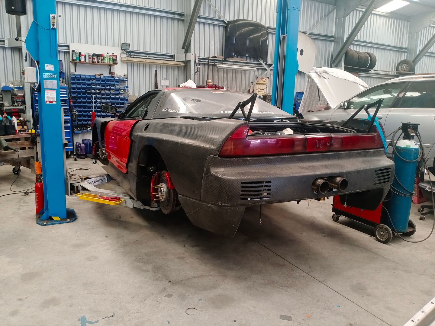
So it was finally ready for the dyno and our local motorsport club Xmas show and tell, and no matter how many times over the years I've seen this car together it always blows my mind. The photo's give you some idea, but it definitely looks better in the flesh.


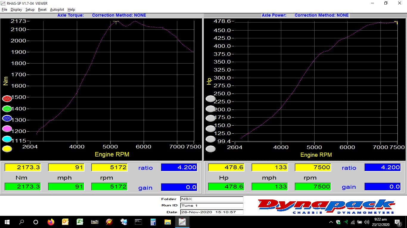
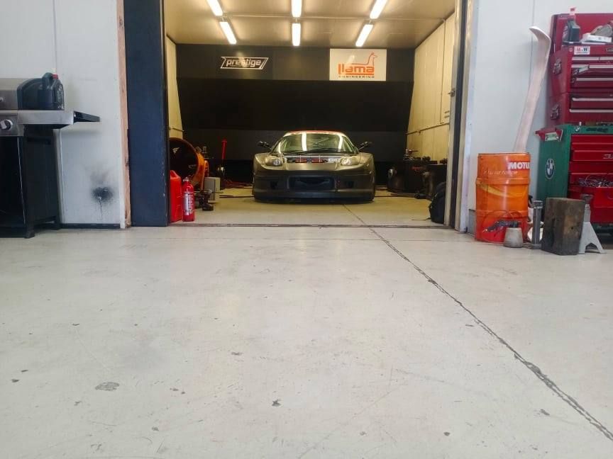
Finally the day came and Chris from Prestige Tuning and Motorsport was on hand to help get the car run in on the dyno. It all went really well after a few wiring headaches (alternator wasn't charging) and we needed to wire in Chris's lamba to CANbus adaptor so he had multiple air/fuel readings. He ran the car for about an hour and a half on and off with different loads and RPM and then we changed the oil and filter again just to make sure we had everything new once again.


https://youtu.be/UZl0J7-ehgM


So there was some good things and bad things that happened............... good was that even with some very preliminary runs (5 or 6) only on wastegate pressure (11psi) the car made 362KW (485hp) at the wheels. So if that continued then we would expect to easily make 520KW (700hp) at the wheels with the boost we expect to run on the high side....... but unfortunately we weren't able to find out for sure as something in the gearbox cried no more .. :(

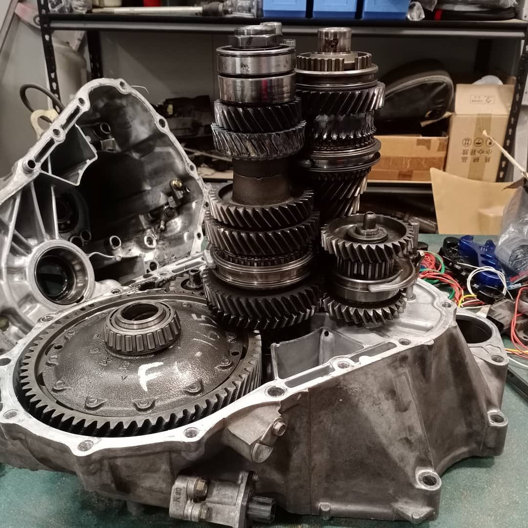
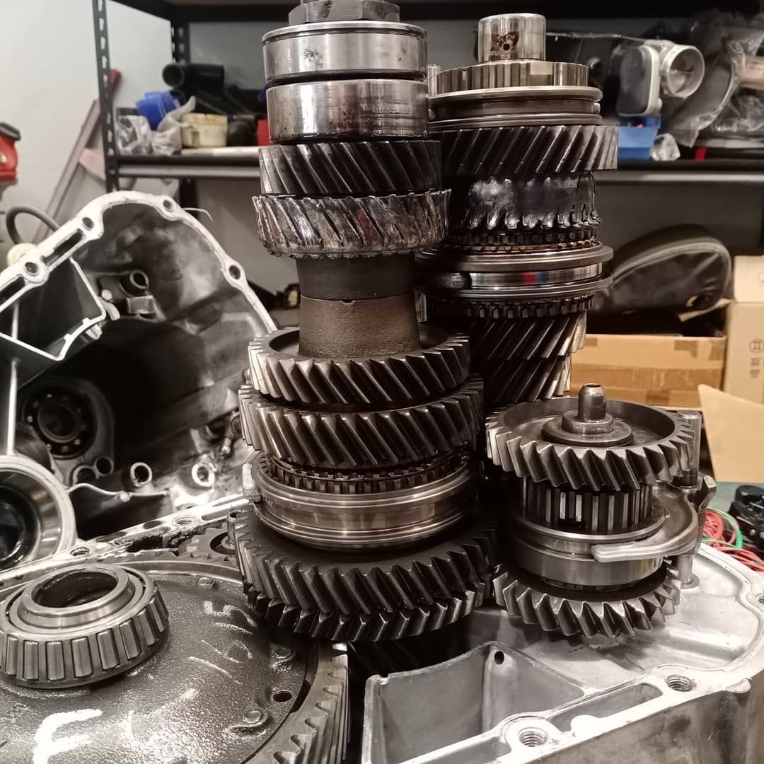
We haven't been able to remove it all to assess what's happened, but I'm happy we had no issues with the engine considering everything in the engine and around it is all brand new, but gutted that something in the gearbox gave up !! :(

We will be back in action once we get the box out and find out what happened.....
 
Last edited:
So I hope everyone had a very merry Xmas and are sitting relaxing ready for 2020 to be over. Then again, I'm not sure 2021 is going to be much better, but at least we all know how to deal with COVID now I guess....... Glass half full, lets assume 2021 is going to be way better !

Hopefully 2021 is going to be better for us as we've now pulled down the gearbox and can quite clearly see the issue at hand !


It's 4th gear which makes total sense since that was the gear we were running on the dyno. Everything else seems to be OK at this stage, but I've got it with a friend who's a gearbox guru to look over at the start of next year so we can get some parts ordered and rebuild it. I was lucky enough to post on the NSX Prime Facebook group already with this info and have found a couple of members who I've purchased some replacement gear stacks from (all of them) just so I have some spares. I was always under the impression that the NSX boxes could take a reasonable amount of power and not fail, but after seeing this some people have commented that in fact they're not that capable at all and they're not surprised that it failed.

To be fair, now I can see that size of the gears in person I can see that they're realistically not going to cope longer term either. We were actually running the car as low as it could possibly go with only 11psi of wastegate pressure when this happened ! It still made 362KW at the wheels though. We plan to replace the gear and see if we can just tune with less throttle opening since we have e-throttle to limit he power so we can get some track time whilst we come up with a longer term gearbox solution.


Also, Shad from Driving Ambition suggested a transmission cooler. It's something I had thought about, but he suggests that it's not a nice to have, but an essential if you ever want to track your NSX, so we're going to do that as well just to make sure we give this thing it's best chance of survival whilst we get some testing done.


https://drivingambitionmotorsports.com/Products/Driving_Ambition_Trans_Cooler_adapter--DA-606
 
Back
Top