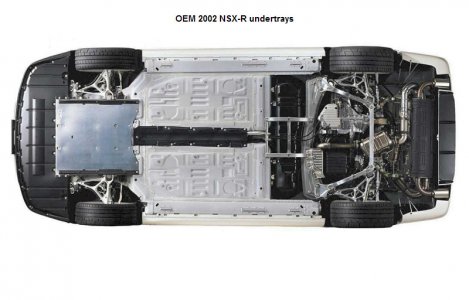
After seeing the rear undertrays / diffusers of John@Microsoft, troca, lowellhigh79, and the Audi R8, I decided to try my hand at building a rear undertray myself. My main goal was to miminize drag subject to the following constraints:
Rear undertray / diffuser:
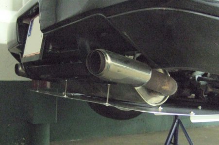
Seeing the finished result, I think that painting the top black would help it absorb heat better instead of reflecting it back at the engine. Painting the air fences, the mounting tabs for the outer air fences, and everything behind the muffler black might also make it less easy to see.
My car is still put up for the winter and the proof of the pudding will be when I take it to the Autobahn. Then I’ll see if the top speed has been impacted, whether the engine overheats quicker, and if the undertray falls off at high speeds. I’ll post up the results.
- Does not require any holes to be drilled into the car anywhere
- Is mounted stably enough that it does not fall off at high speeds
- Uses attachment points that allow for relatively easy mounting and dismounting
- Is made of a material that it cannot burst into flames even if it’s mounted close to glowing hot exhaust pipes and catalytic converters, does not corrode, and does not cause contact corrosion where it touches the NSXs body
- Is shaped so that it does not get hit by the engine as it rocks, the exhaust system as it sways, and the tires and suspension arms as they travel through their full range of motion
- Does not hinder jacking up the car
- Does not have to be removed to do an oil change
- Causes as little additional scraping as possible when entering driveways
- Tries to maintain proper engine cooling
- Is visually unobtrusive
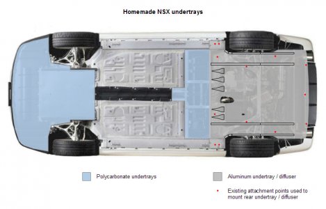
- 2mm AlMg3 aluminum alloy sheet, also used to build the hulls of ocean-going ships
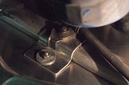
- Mounted only using existing mounting points and it seems to be very stable
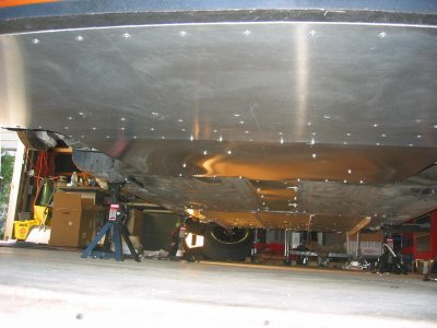
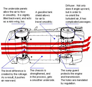
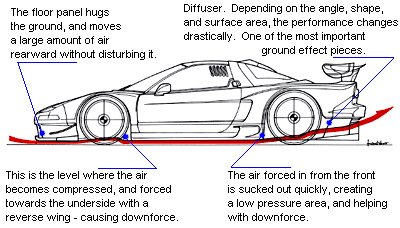
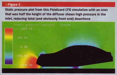
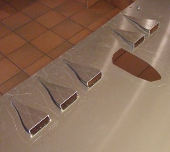
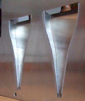
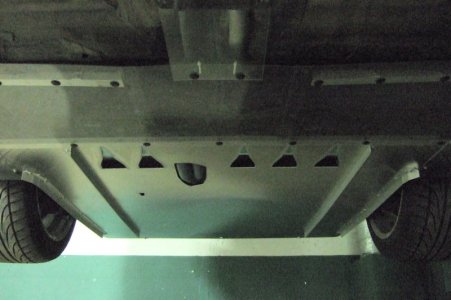
- Fuel tank undercover made shorter so that the diffuser could be made longer, allowing for NACA ducts to feed air to the oil pan and gearbox. Moved cross member that supports the rear of the fuel tank undercover forward (towards nose of car) by 8 cm. That was as far as it could be moved before interfering with jack the points. The ends of the cross member are no longer attached directly to the chassis but rather to 3 mm thick AlMg3 mounting plates. The NACA ducts are 175 mm long with 19*77 mm inlet openings and were constructed following the guidelines in NACA report naca-rm-a7i30.
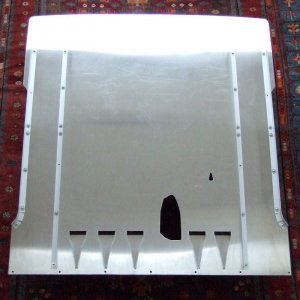
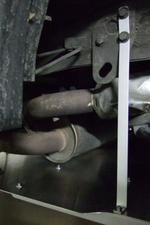
- Diffuser starts upsweep as far forward as possible and the upsweep does not exceed 5°. A slight upsweep decreases drag. A greater upsweep creates downforce but doesn't reduce drag as much. An even greater upsweep is good for bling but bad for both drag and downforce. A Honda Insight has a 5° upsweep to its rear diffuser to mimimize drag. An Aston Martin DBR9 race car uses 9° to maximize downforce. My undertray is flat until the trailing edge of the engine subframe (rear beam rod A). From there until the muffler the upsweep is 1.6° (the angle is limited by the position of the OEM catalytic converters and OEM-sized muffler). Behind the muffler the upsweep is 5°.
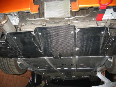
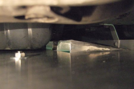
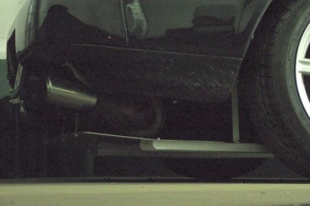
- Strengthening cross members for the diffuser run along the axis of the car and stick down into the airflow, doubling as air fences, since there was not enough space for them to stick up into the engine compartment and exhaust area. This negatively impacts ground clearance and rear brake cooling but should help aerodynamics.
Rear undertray / diffuser:
- 1x 1409*1250*2 mm sheet of AlMg3
- 1x 400*200*2 mm piece of AlMg3 to make the 10 side walls of the 5 NACA ducts
- 1x 1295*25*25 mm L-shaped anodized aluminum for front cross member (also supports the trailing edge of fuel tank undercover)
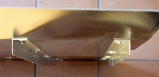
- 2x 137*225*3 mm AlMg3 for front cross member mounting plates
- 2x 100*20*2 mm anodized aluminum for front cross member mounting tabs
- 2x 1146*25*25 mm L-shaped anodized aluminum for the inner air fences
- 2x 85*60*2 mm AlMg3 for the inner air fence mounting tabs
- 2x 946*25*25 mm L-shaped anodized aluminum for the outer air fences
- 2x 420*20*2 mm anodized aluminum for the outer air fence mounting tabs
- 24x M6*12 mm stainless steel screws with semi-spherical allen key heads to mount the air fences to the undertray (M6x10mm would have been better but my local hardware store doesn’t carry any)
- 2x M6*14 mm stainless steel screws with semi-spherical allen key heads to fasten the inner air fences and undertray to the mounting tabs
- 2x M6*12 mm stainless steel screws with semi-spherical allen key heads to fasten the outer air fences and undertray to the mounting tabs
- 2x M6*100 mm threaded stainless steel rods for outer rear attachment points
- 1x M5*110 mm threaded stainless steel rod for inner rear attachment point
- 7x OEM NSX push-clips
- 2x M5*8 mm stainless steel screws with semi-spherical allen key heads to attach the front cross member to the mounting plates
- 2x M5*8 mm stainless steel screws with hex heads to attach the front cross member to the mounting tabs
- 28x M6 stainless steel nuts
- 6x M6 stainless steel low-profile nuts
- 7x M5 stainless steel nuts
- 54x M6*20 mm zinc-plated steel washers
- 4x M6*30 mm zinc-plated steel washers
- 2x M6*25 mm zinc-plated steel washers
- 2x M6*20 mm stainless steel washers
- 2x M5*30 mm zinc-plated steel washers
- 1x M5*15 mm stainless steel washer
- 8x M5*8 mm plastic washers
- J-B Weld adhesive for the walls of the NACA ducts
- 10.3 kg for the finished rear undertray / diffuser including air fences and mounting hardware
Seeing the finished result, I think that painting the top black would help it absorb heat better instead of reflecting it back at the engine. Painting the air fences, the mounting tabs for the outer air fences, and everything behind the muffler black might also make it less easy to see.
My car is still put up for the winter and the proof of the pudding will be when I take it to the Autobahn. Then I’ll see if the top speed has been impacted, whether the engine overheats quicker, and if the undertray falls off at high speeds. I’ll post up the results.
Attachments
-
 NSX-R undertrays.jpg96.2 KB · Views: 2,039
 -
 Homemade undertrays.jpg96.2 KB · Views: 2,196
 -
 Rear undertray.jpg95.9 KB · Views: 2,227
 -
 NACA ducts top.jpg93.7 KB · Views: 3,105
 -
 NACA ducts bottom.jpg95.9 KB · Views: 2,151
 -
 Upsweep angles.jpg88.6 KB · Views: 1,546
 -
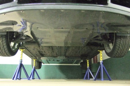 All undertrays mounted.jpg96.3 KB · Views: 1,824
 -
 Rear undertrays mounted.jpg92.9 KB · Views: 2,953
 -
 Oil pan and NACA ducts.jpg90.4 KB · Views: 1,519
 -
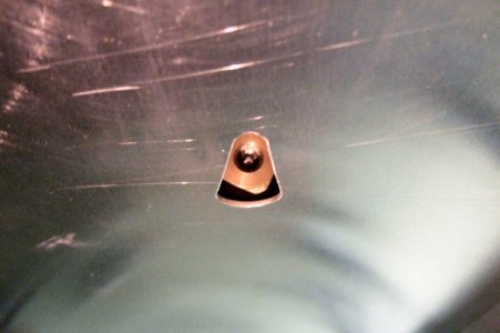
 Inner air fence mounting tab.jpg90.8 KB · Views: 1,428
 -
 Outer air fence mounting tab.jpg90.5 KB · Views: 1,485
 -
 Rear mounting points.jpg96.4 KB · Views: 1,906
 -
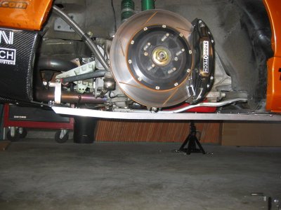
 Ground clearance.jpg91.3 KB · Views: 1,523