• Protip: Profile posts are public! Use Conversations to message other members privately. Everyone can see the content of a profile post.

Downforce radiator duct? {new style}

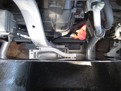
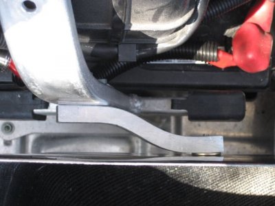
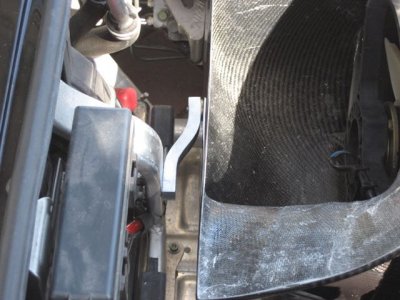
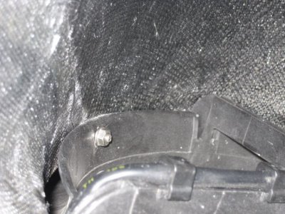
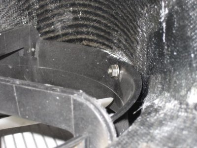
Any of you guys have instructions on how to install this? I put on the duct but can't figure out how the Nut + Rod + Spacer works at all.

Other users like Raw and Nero had to fab up something that attached to the spare tire bracket.

I have the same question....
 
Duct

Nero;

Is that an OEM Type-R hood duct / vent?
If so, what kind of hood do you have?
I've always wanted to get one for my VIS hood but afraid it wouldn't fit and they aren't cheap as i'm sure you know.

Cheers
nigel
 
A threaded rod replaces a bolt on the middle of the fan... It goes through the duct and a nut fits behind the duct. Thata how I did it and you need a metric rod. I can take pics. I have extra rod if anyone wants some... Of.... My rod. I knew this wouldn't sound right. Anyway... I'll snap some photos tomorrow. This metric rod isn't readily available I had to but 3 long ones to get just the 1/2 that I needed. Downforces own solution fails over time.
 
Since the downforce rod doesn't work and I'm not going to have room for the spare tire bracket anymore due to VRH, I'll take the extra rod please! Give me your rod Dave! Haha
 
LMAO... How many inches do you need because it's at least 2 feet long. :D
 
[emoji23] whoah I didn't know you had so much rod to give out
 
They may have changed this over time but what I received was not a threaded rod. It was a bolt that was JB welded. I forget the exact configuration now but that weld/glue or whatever it was came apart. I JB else's it back and over time it came apart again. I realized the solution is a rod and two nuts (I just can't get away from this joke) l. I'll take some pics today and post and also of the metric rod. Which anyone can have as long as they pay for the shipping.
 
For your information

The hood screen is installed into the worng direction.

1241c9010154e21694c1d8d26f7bf9dd.jpg


This is how it should look

photo-11438-7282915e.jpg

photo-11437-10e2fe75.jpg


Please see pictures from KAZ (UK) blog side

http://www.nsxcb.co.uk/entry.php?1563-Brake-OH-etc-06&goto=prev
 
They may have changed this over time but what I received was not a threaded rod. It was a bolt that was JB welded. I forget the exact configuration now but that weld/glue or whatever it was came apart. I JB else's it back and over time it came apart again. I realized the solution is a rod and two nuts (I just can't get away from this joke) l. I'll take some pics today and post and also of the metric rod. Which anyone can have as long as they pay for the shipping.

Thanks Turbo2Go. DF provided a threaded rod and two nuts. So they may have got it right now. I will have to take a closer look at the fan to see how the rod is supposed to attach.
 
I have my own method. PM your email, Ill send you a pic
 
Nice catch Detlef ! Good eye.

I was looking at the duct and I didn't see it. I still want to install one of those Type-R ducts on my VIS bonnet but i'm not sure they will fit or can be modified to work.
When I find out if they will, i'll be having one.

Oh yeah, back to the original post;
My duct came with the rod, (actually a hollow tube) with the nuts bonded inside it and the nuts just pulled out under tension.
I drilled the rod and the nut and inserted an aircraft s/s cotter pin, (split pin to some) some Pro-Seal and now no worries.

Nero;
As in post #2, what kind of hood do you have, please?

Cheers
nigel
 
Last edited:
A threaded rod replaces a bolt on the middle of the fan... It goes through the duct and a nut fits behind the duct. Thata how I did it and you need a metric rod. I can take pics. I have extra rod if anyone wants some... Of.... My rod. I knew this wouldn't sound right. Anyway... I'll snap some photos tomorrow. This metric rod isn't readily available I had to but 3 long ones to get just the 1/2 that I needed. Downforces own solution fails over time.

Is your rod really thin.:redface:
 
hahaha

Anyway here is a pic of what I currently use. This is a threaded metric steel rod that screws into a bolt hole at the center area of the engine fan replacing a bolt. It goes through the duct and on the other side I secured it with a fender washer and a wing not for easy removal. I heat shrinked the center of the rod to protect it from the elements. You could think of it as a condom for your rod. Hehe I highly recommend protection.

C521AE0F-056B-450D-93A2-0180D0AC33A7_zpsqksryeda.jpg
 
Thanks Detlef I may get around to changing it nut I kinda like it this way too. Nigel I have the DF Carbob/Carbon hood
 
IMG_2298.jpgIMG_2299.jpgIMG_2300.jpgIMG_2301.jpgIMG_2302.jpg
 
I made it :wink:
I didn't like the downforce one :frown:
 
With the help of [MENTION=8153]jagtiger[/MENTION], I was able to finally figure out how to mount this thing after not being able to figure it out after so much time.

It's very "un-elegant" of them to design it to mount this way but I suppose it is the easiest in terms of engineering and manufacturing. The way [MENTION=9191]03 raw nsx[/MENTION] has it is much better looking as it doesn't have a rod randomly in the middle of the duct. But it is what it is.

Here's the steps:

1) Remove the top most nut (1/3 nuts) with a 10mm socket (thin walled). I used a 3/8 ratchet a extended 10mm socket. It helps to have a magnetic tool to pull out the nut incase it is difficult to remove my hand out of where it sits.

2) Install the thread extender that is included with the duct. It is about an inch and silver. Tighten that down to where you removed the OEM nut previously.

3) Put on the duct

4) Thread the rod into the extender

5) Install and tighten the 10mm nut on the most outside of the duct which finally secures it.
 
FYI for anyone wanting to know more about the Type R Aero:
http://world.honda.com/NSX/technology/t3.html

[FONT=Arial, Helvetica, sans-serif]A front hood air duct:
the aerodynamic mechanism for creating downforce

[/FONT][FONT=Arial, Helvetica, sans-serif]At the rear, downforce is easily obtained using a wing-type spoiler. At the front, though, adding too big an aerodynamic device can negatively affect minimum ground clearance and/or the approach angle. Increased aerodynamic resistance resulting in reduced acceleration is also another example of the many problems associated with obtaining appropriate downforce in a road-going car.

The solution we chose was to design the underbody of the car as flat as possible to encourage smooth airflow under the car, maintaining airflow speed to create downforce. This method not only provides for adequate ground clearance and approach angle but also does not unduly increase the forward-protruding surface of the body. However, this led to a new problem: how to extract the airflow through the front radiator that had previously been channeled underneath the car?

Taking advantage of the car's mid-ship layout, an air duct was added in the front hood to provide the necessary extraction route. Longitudinal fins were also added to the outer left and right sides of the front under-cover tray to prevent the air passing under the car from entering the front wheel wells. Similarly, spats have been added to both sides of the air ducts to channel air passing through the ducts away from the wheel wells. The opening ratio under the front bumper has also been reduced to limit as much as possible the actual amount of air flowing through. All these innovations result in a smoother airflow both under the body and through the front hood, achieving the desired downforce.

No large aerodynamic appendage was required, helping maintain the original NSX's overall design and ensure a relatively low aerodynamic drag. Downforce was thus achieved without sacrificing top speed.

Wind tunnel tests have shown that when the car is at an angle relative to wind direction, the longitudinal fins of the front under-cover tray function in the same way as the chin spoiler, effectively reducing body lift and improving transient characteristics.

[FONT=Arial, Helvetica, sans-serif]Wind tunnel testing[/FONT]
space.gif
t3_01.jpg
space.gif

[FONT=Arial, Helvetica, sans-serif]View of the underbody[/FONT]
space.gif
t3_02.gif


space.gif

<tbody style="padding: 0px; margin: 0px;">
</tbody>
space.gif
space.gif
space.gif
[FONT=Arial, Helvetica, sans-serif]Cd (Drag coefficient): 0.32
Cl (Lift coefficient/overall): -0.100
Clf (Lift coefficient/ front): -0.040
Clr (Lift coefficient/rear): -0.060
[/FONT]

[FONT=Arial, Helvetica, sans-serif]Compared to the original NSX-R, this translates into an increase in vertical force acting on the front tires of 36.2kgf, and of 25.0kgf on the rear tires (test results measured at 180 km/h in both cases).[/FONT]
space.gif
space.gif
[FONT=Arial, Helvetica, sans-serif]Lift reduction measures (effect measured piece-by-piece)[/FONT]
space.gif

t3_03.gif

space.gif
space.gif
space.gif
space.gif

<tbody style="padding: 0px; margin: 0px;">
</tbody>
space.gif
space.gif
space.gif
space.gif
[FONT=Arial, Helvetica, sans-serif]Extensive circuit testing to determine the optimum
equilibrium between downforce and front-to-rear balance
[/FONT]
[FONT=Arial, Helvetica, sans-serif]
The air duct in the front hood could have been made simply by cutting an opening and trimming the edges with plastic. But because we wanted to maintain the beauty of the original design including the simplicity of line worthy of a car cut for speed like the NSX-R, and to reach the weight reduction target we had set for ourselves, we chose carbon fiber instead. The rear spoiler is similarly a single piece of carbon fiber designed to achieve the required downforce while maintaining a low drag coefficient in a simple shape embodying functionality and beauty.

Both parts are formed using an autoclave, a method more often seen in aircraft manufacture. Multiple layers of pre-pregs made of resin-impregnated carbon fibers are cured in a high-pressure oven to form the parts. The front hood is made of carbon Aramid fibers for added resistance to tearing. In the event of an accident, it is designed not to shatter into small pieces. During the laminating process, fibers are offset by 45 degrees, with each layer above and below being symmetrically angled to provide equal strength in all directions.

Nine to ten hours are required to complete the laminating process of each single part. After lamination, the whole lay-up is wrapped in a baking film, and a vacuum is applied to consolidate the laminate prior to curing for 2-3 hours in the autoclave at a pressure of two to three atmospheres. Once in the autoclave, it takes one hour to bring the part to temperature, while some five hours are required for the cooling down process. Air released from the resin when liquefying at high temperature is carefully bled off to form a strong CFRP (Carbon-Fiber Reinforced Plastic).

The front hood's outer skin is formed separately from the inner frame before being glued together. Glue thickness is strictly maintained at less than 0.5mm. The resultant strength is superior to that of the base materials. The rear spoiler is a hollow, one-piece molding made using a proprietary process developed in cooperation with a parts supplier.

Durability, a matter not normally emphasized in aerodynamic carbon fiber parts manufacture, has been pursued to the utmost. In all aspects of the product, durability on par with steel is achieved. The painting process has also been the object of painstaking attention, especially regarding the undercoating, with both parts undergoing a "5 coat/5 bake" process. For the front hood in particular, paint has been applied so as to let the roughness of the carbon fiber surface show through ever so slightly.[/FONT]

space.gif
t3_06.gif

space.gif
space.gif
space.gif

t3_04.jpg

space.gif

t3_05.jpg
space.gif
space.gif
space.gif

<tbody style="padding: 0px; margin: 0px;">
</tbody>
[FONT=Arial, Helvetica, sans-serif]In order to endow the new NSX-R with outstanding high-speed performance, we turned our attention to aerodynamics and their effect on high-speed cornering power, braking, turn-in, and other aspects affecting vehicle controllability. This led us to a new technical approach called "aerodynamically-induced stability". In addition to increasing high-speed cornering power, we have also striven to improve vehicle control quality - the ease with which the driver can control the car, and thus exploit its full potential. This enabled the chassis to be tuned for reduced understeer at low to medium speeds. The resultant improved handling at both low and high speeds endows the New NSX-R with outstanding speed on all types of circuits.[/FONT]
space.gif
space.gif
[FONT=Arial, Helvetica, sans-serif]The third advantage of downforce is that it helps reduce body roll as well as body pitch. This in turn helps reduce sudden variations in vertical forces applied to the tires at the limit, increasing vehicle stability in the wake of driver input. Vehicle behavior is also more linear near the limit of adhesion, contributing to increased driver control. In other words, creating downforce to press the vehicle onto the road as speed increases not only contributes to increased absolute cornering speed and thus absolute dynamic performance, but also significantly improves vehicle control quality as measured by response to driver inputs and vehicle stability at the limit. These are the fundamentals behind downforce and aerodynamic stability as a means to improved high-speed vehicle handling.[/FONT]
space.gif

<tbody style="padding: 0px; margin: 0px;">
</tbody>

[FONT=Arial, Helvetica, sans-serif]Downforce balance front to rear (Straight-line driving at constant speed)[/FONT]
t2_03.gif

space.gif

[FONT=Arial, Helvetica, sans-serif]By creating a downforce with the same front-to-rear balance as vehicle weight, changes in steering characteristics from low to high speeds remain well under control. At higher speeds this translates into a more linear response. More precise control of the vehicle helps the driver delve further into the car?s potential.[/FONT]
space.gif

<tbody style="padding: 0px; margin: 0px;">
</tbody>

<tbody style="padding: 0px; margin: 0px;">
</tbody>
[/FONT]
 
Back
Top