One of my toughest work on an NSX radio was completed as of this morning. The French radio came in with multiple issues at the same time:
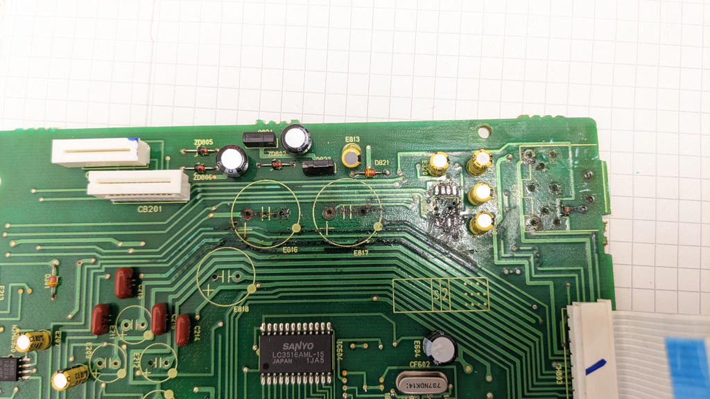
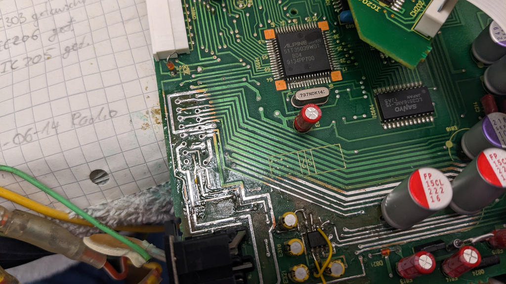
Affected areas need to be cleaned down to bare metal to remove any contamination and inspect for broken traces - and there were many (especially around the CD port OP amp)

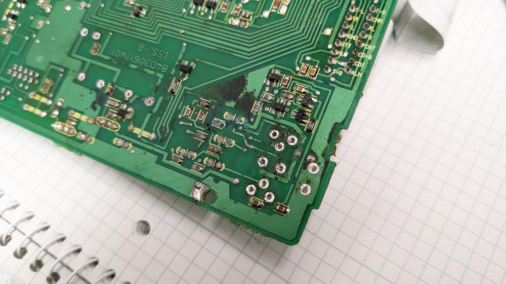
The backside of the PCB was affected as well - usually a sign of heavy damage.
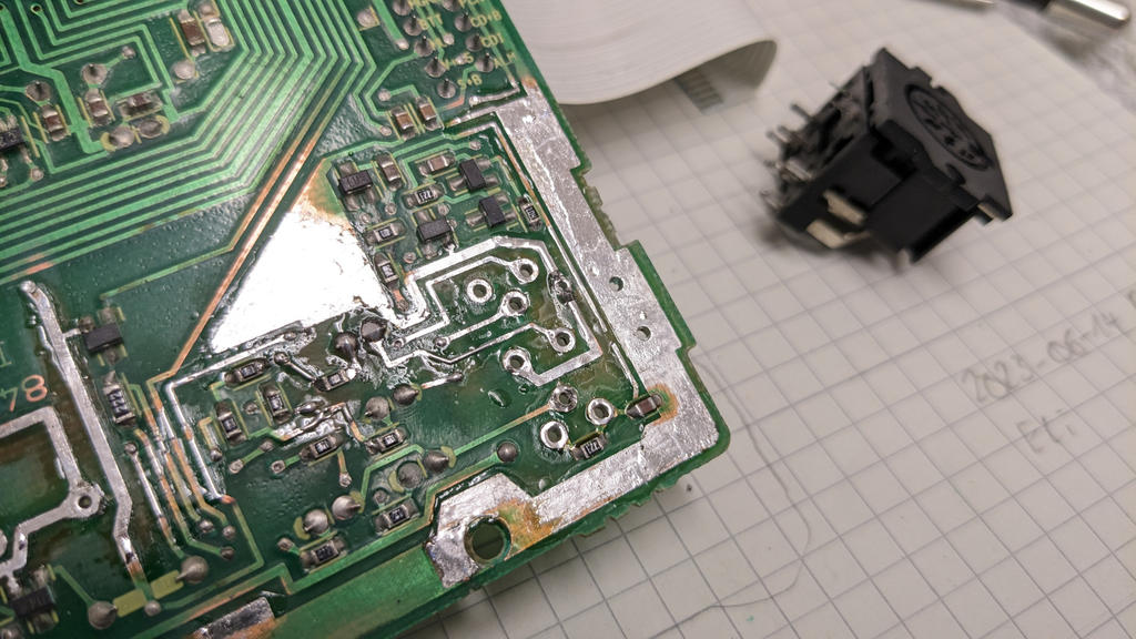
The new CD port OP amplifier needed significant work until it was connected correctly and working again.
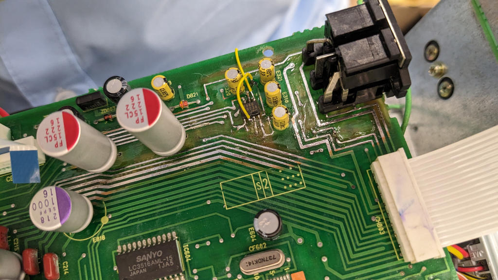
Now we had a working CD port but not much more. Still a ticking sound at the speakers and distortions on cassette and radio. Using freeze spray, an area near one of the large flex cable connectors, was identified to be very sensitive to temperature changes and correlating with the knocking noise.
Checks and replacements of all components nearby brought no improvement and so the connector itself was exchanged and all Vias re-soldered. After that, the knocking sound was gone but still audible distortions after the radio was switched off for several hours.
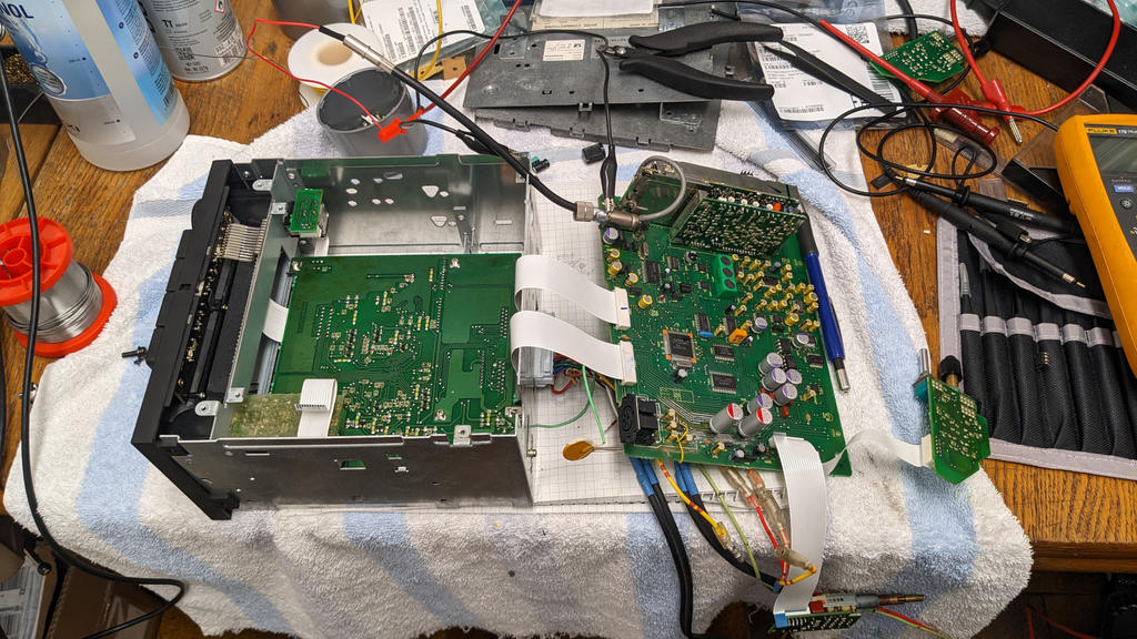
More time to reverse engineer the audio path. For those interested, the CD audio passes more or less directly to the volume and tone control and from there to the final output stage - and works flawlessly. Radio and cassette additionally run through a Dolby noise reduction chip, followed by the digital noise reduction chip and the muting circuit before taking the same path.
Since CD was working fine the issue needed to be on that extra path. After replacing many more capacitors (~30 pieces), the multiplexer chip, the quad OP amp and a the noise reduction chip the situation did not improe - a truly frustrating experience. As all these parts were initially OK there was only the muting circuit left.
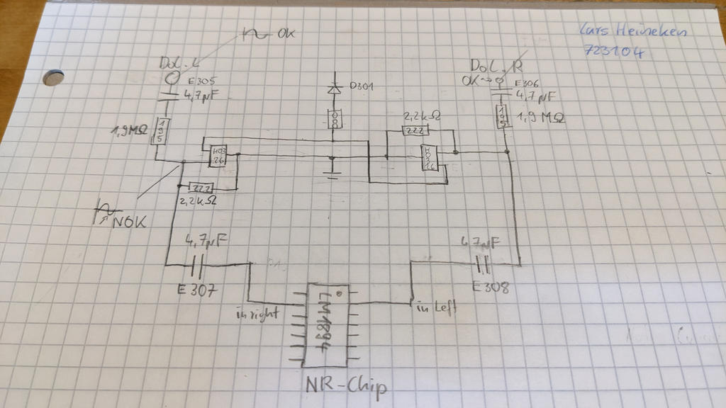
The signal at the Dolby chip looked perfectly but went distorted once it reached the muting circuit. It's based on two digital transistors (H03) controlled by a very long muting line that travels through the lower and middle PCB. This line turned out to have a too high DC level with stray signals on top. When grounding the muting control line the distortions completely went away.
While tracing the muting control line across the boards I came along a second flex cable connector that was contaminated, too. Some of the pins measured a resistance as low as 200 kΩ which are supposed to have >2 MΩ. A replacement of the connector and cleaning of the area improved the situation but did not fix it completely. Whenever the radio was switched of for ~24 hours the distortions returned.
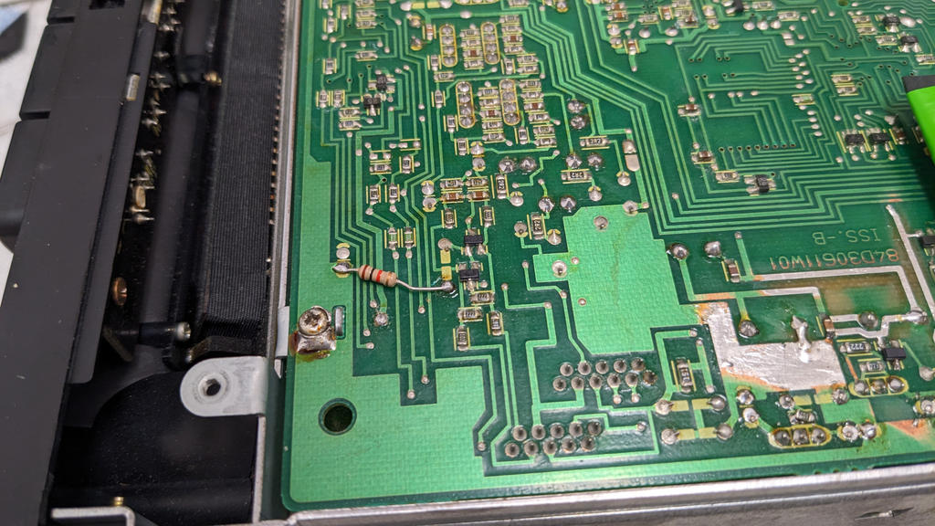
As a final remedy a 1 kΩ resistor was installed as a pull-down on the muting control line. It's more of a patch than a fix but it works fine, removing all distortions while retaining the muting functionality. Since the muting signal is only active while tuning or operating the cassette, the extra load shouldn't be a problem.
The radio tested fine for several hours with the full functionality and will return to it's owner soon. Hopefully it's a permanent fix and can be added to the blog for further reference ..
What can be taken away:
- CD port non-operational
- Aggressive scratching noise when turning the volume knob
- A loose volume knob
- Permanent knocking sound even with zero volume
- Distortions on radio and cassette fading away after multiple hours
- Strong acid damage
Affected areas need to be cleaned down to bare metal to remove any contamination and inspect for broken traces - and there were many (especially around the CD port OP amp)
The backside of the PCB was affected as well - usually a sign of heavy damage.
The new CD port OP amplifier needed significant work until it was connected correctly and working again.
Now we had a working CD port but not much more. Still a ticking sound at the speakers and distortions on cassette and radio. Using freeze spray, an area near one of the large flex cable connectors, was identified to be very sensitive to temperature changes and correlating with the knocking noise.
Checks and replacements of all components nearby brought no improvement and so the connector itself was exchanged and all Vias re-soldered. After that, the knocking sound was gone but still audible distortions after the radio was switched off for several hours.
More time to reverse engineer the audio path. For those interested, the CD audio passes more or less directly to the volume and tone control and from there to the final output stage - and works flawlessly. Radio and cassette additionally run through a Dolby noise reduction chip, followed by the digital noise reduction chip and the muting circuit before taking the same path.
Since CD was working fine the issue needed to be on that extra path. After replacing many more capacitors (~30 pieces), the multiplexer chip, the quad OP amp and a the noise reduction chip the situation did not improe - a truly frustrating experience. As all these parts were initially OK there was only the muting circuit left.
The signal at the Dolby chip looked perfectly but went distorted once it reached the muting circuit. It's based on two digital transistors (H03) controlled by a very long muting line that travels through the lower and middle PCB. This line turned out to have a too high DC level with stray signals on top. When grounding the muting control line the distortions completely went away.
While tracing the muting control line across the boards I came along a second flex cable connector that was contaminated, too. Some of the pins measured a resistance as low as 200 kΩ which are supposed to have >2 MΩ. A replacement of the connector and cleaning of the area improved the situation but did not fix it completely. Whenever the radio was switched of for ~24 hours the distortions returned.
As a final remedy a 1 kΩ resistor was installed as a pull-down on the muting control line. It's more of a patch than a fix but it works fine, removing all distortions while retaining the muting functionality. Since the muting signal is only active while tuning or operating the cassette, the extra load shouldn't be a problem.
The radio tested fine for several hours with the full functionality and will return to it's owner soon. Hopefully it's a permanent fix and can be added to the blog for further reference ..
What can be taken away:
- Freeze spray can be a very helpful tool
- Contaminated flex cable connectors can cause stray connections that disturb the sensible audio path - if contamination is suspected they should be replaced
- The muting circuit has been understood and documented. In a worst case situation it can de disabled since it's a comfort function
- A pull down resistor of 1 kΩ on the muting control line seems not to cause further issues


