Transmission Swap pt1
Months of planning and parts collecting all comes down to this week. I'll split up the posts by day to make this project easier to follow along.
Here are some sources & references I'm using. I have a huge parts list to share as well if you'd find it useful.
FancyCraft - JP blog site for parts lists, walkthrough, wiring, etc. One of the most helpful sources of info especially for RHD cars but missing some info.
https://fancy-craft.firebaseapp.com/NSX/report/at-mt/report1.htm
Drew - He wrote his own swap guide which is my main basis for the project. He can provide it if you ask, I haven't asked for permission to distribute it yet.
http://www.nsxprime.com/forum/member.php/5430-drew
Wayne - Provided the majority of the RHD swap parts and also wrote the guide for it.
http://www.nsxprime.com/forum/member.php/10956-whrdnsx
Cycle Terminal - OEM connectors for wiring harnesses, tools, wiring supplies.
http://www.cycleterminal.com/index.html
Speedhunters "Project NSX" - good read for inspiration and some extra info.
http://www.speedhunters.com/2018/03/project-nsx-manual-transmission-swap/
NSX1 Blog - Shifter parts, short shifter install.
http://www.nsx1.com/shifter.html
Acura factory service manual volumes 1 & 2, NSX Electrical Troubleshooting Manual (1992)
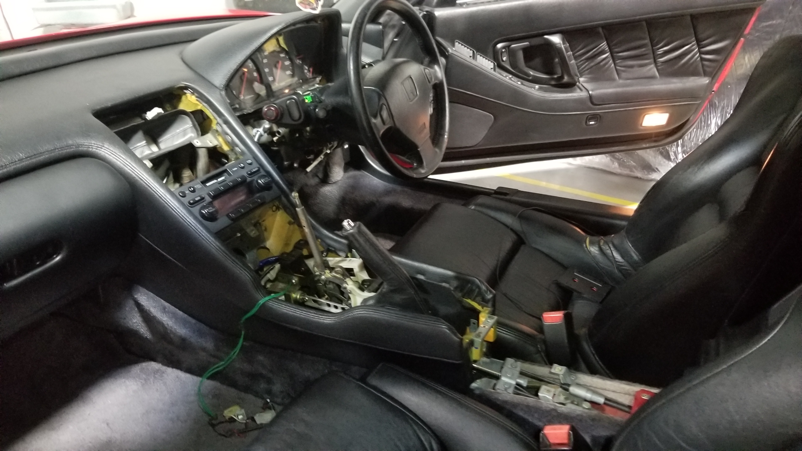
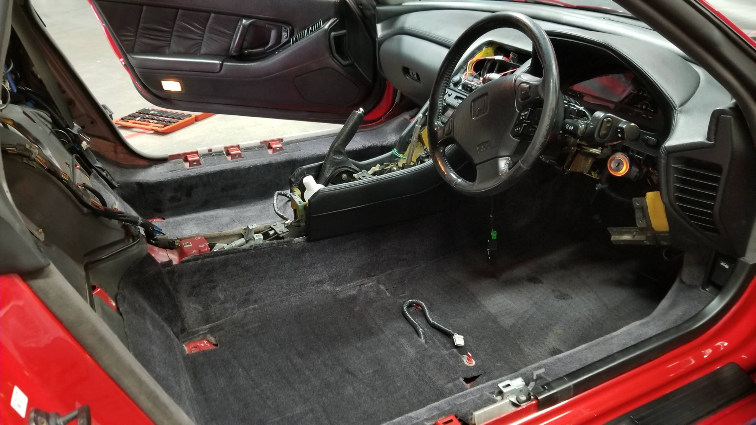
Day 1 is interior focused. Pedal box and wiring. See previous posts for the gauge cluster swap and center console removal.
"First" order of business is seat removal. Easy with the instructions in the factory service manual (FSM). Four anchor bolts, one seat belt retainer, one connector each seat. Lift out carefully, they're heavy. I wouldn't dream of doing the next steps without at least the driver's seat out, but just take both out anyways.
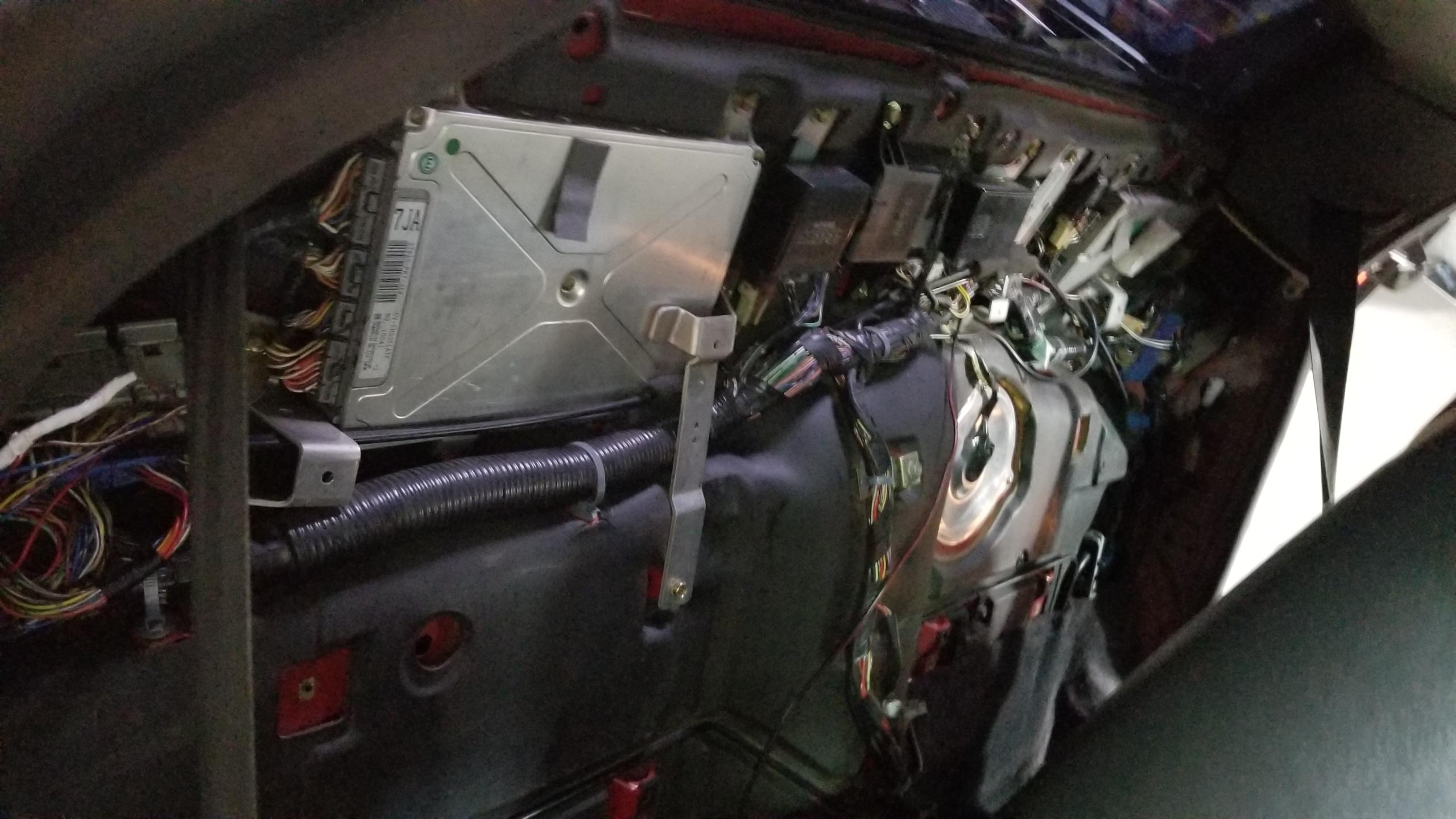
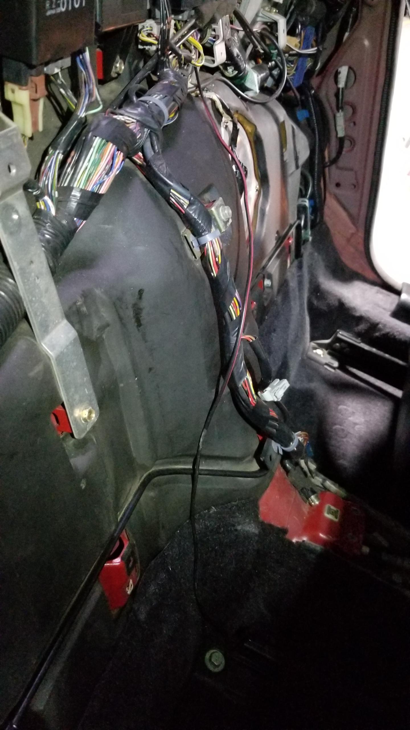
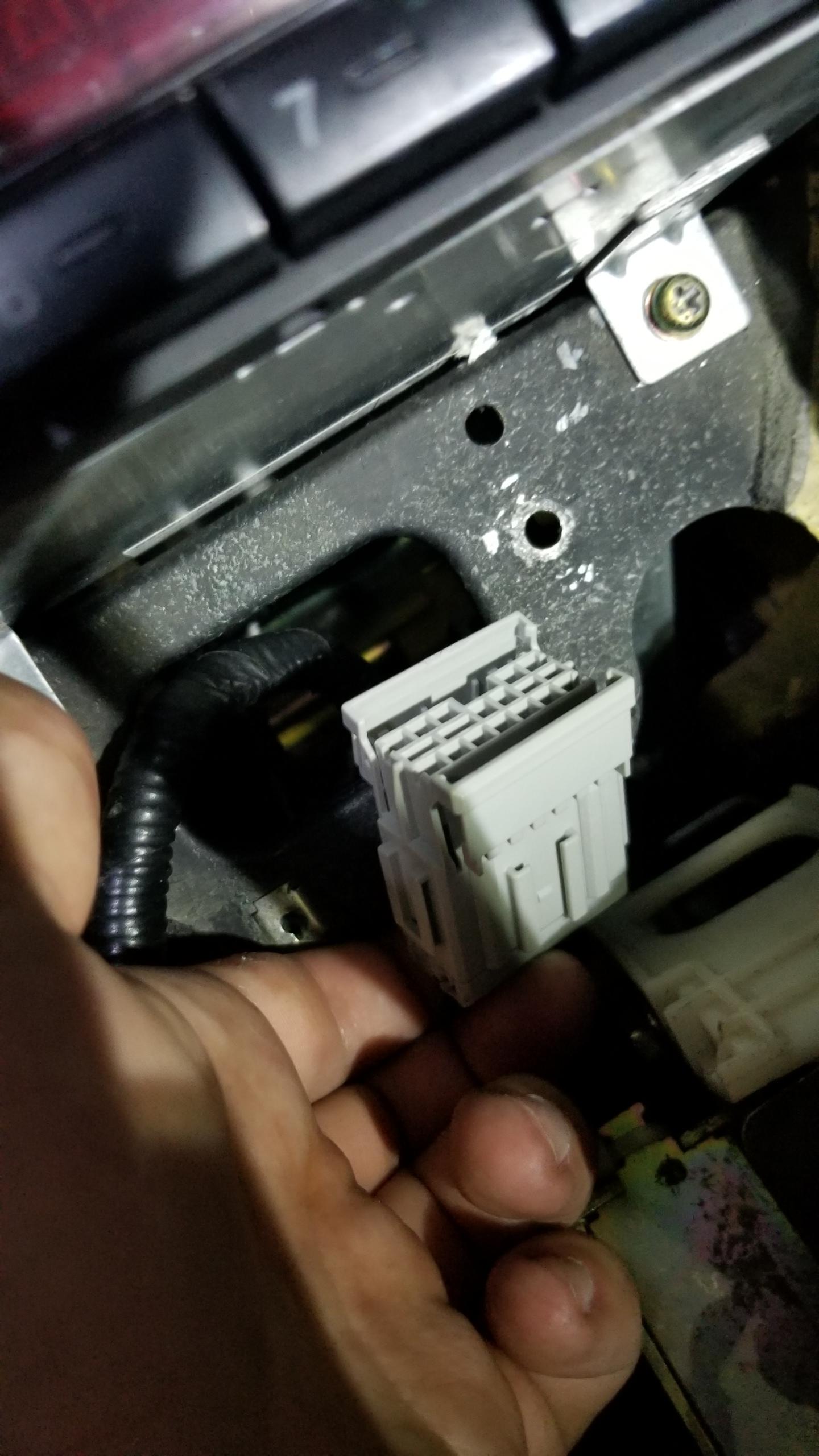
Next, steering column removal. Disconnect the battery. Disconnect a bunch of connectors for the ignition switch, combination switches, SRS, whatever else is attached to the column BEFORE taking the mount bolts off to avoid ripping out wires.
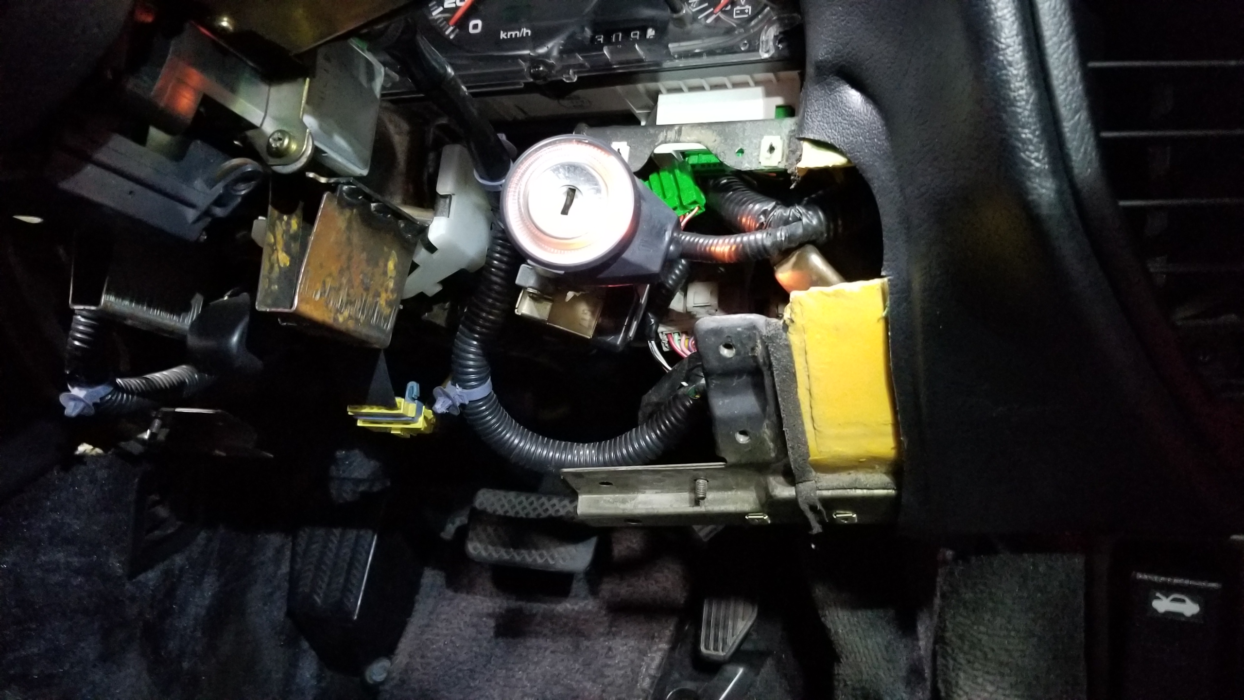
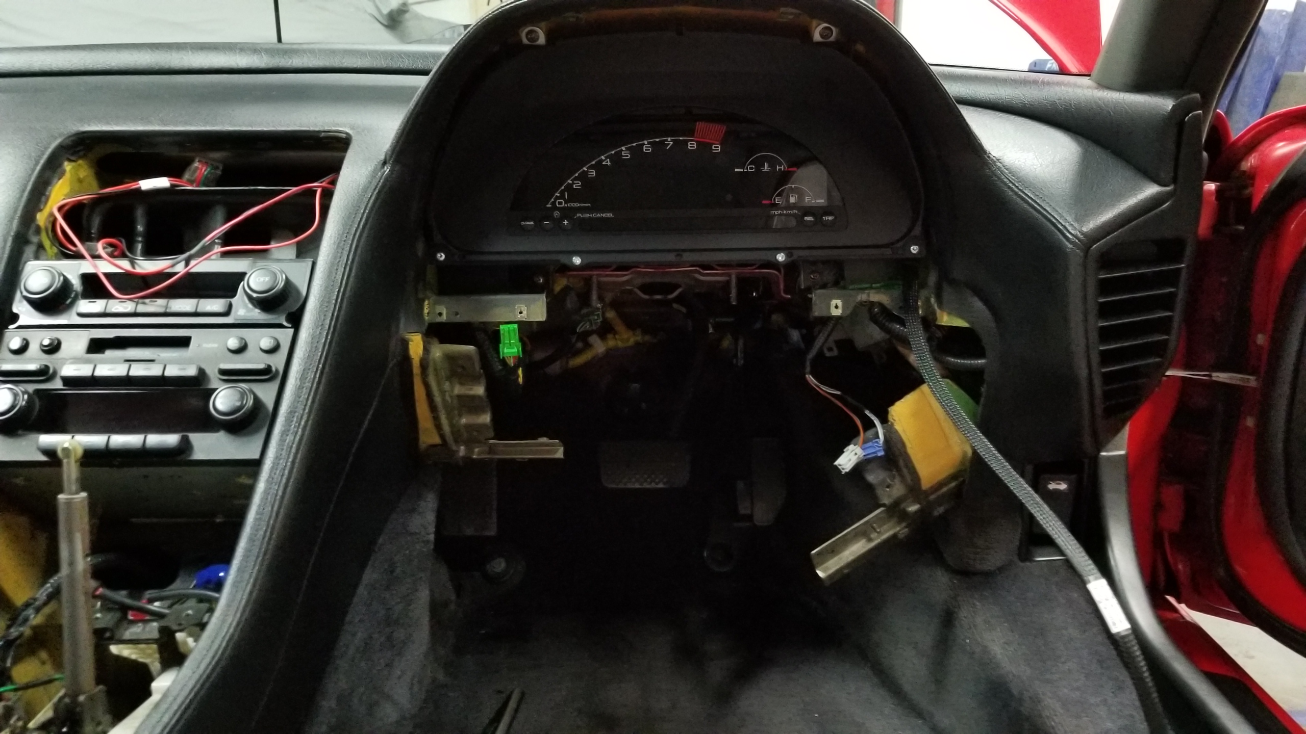
Two bolts on the U-joint, two on a U-bracket, and two more nuts towards the top and the column comes right out. While you're on your back getting the last bolt out, it would be best to have a helper lift out the column from above, it's also heavy.
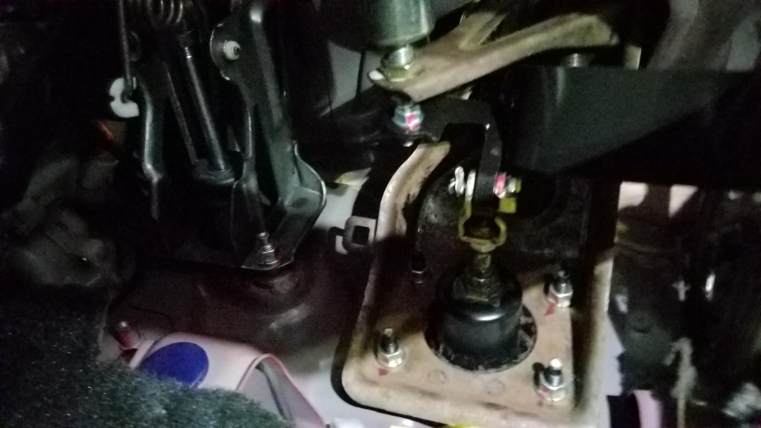
You can see the right part of the lower dash already broken off from some previous work. I'll have to glue it back in place later on. Maybe JB weld or something would work best.
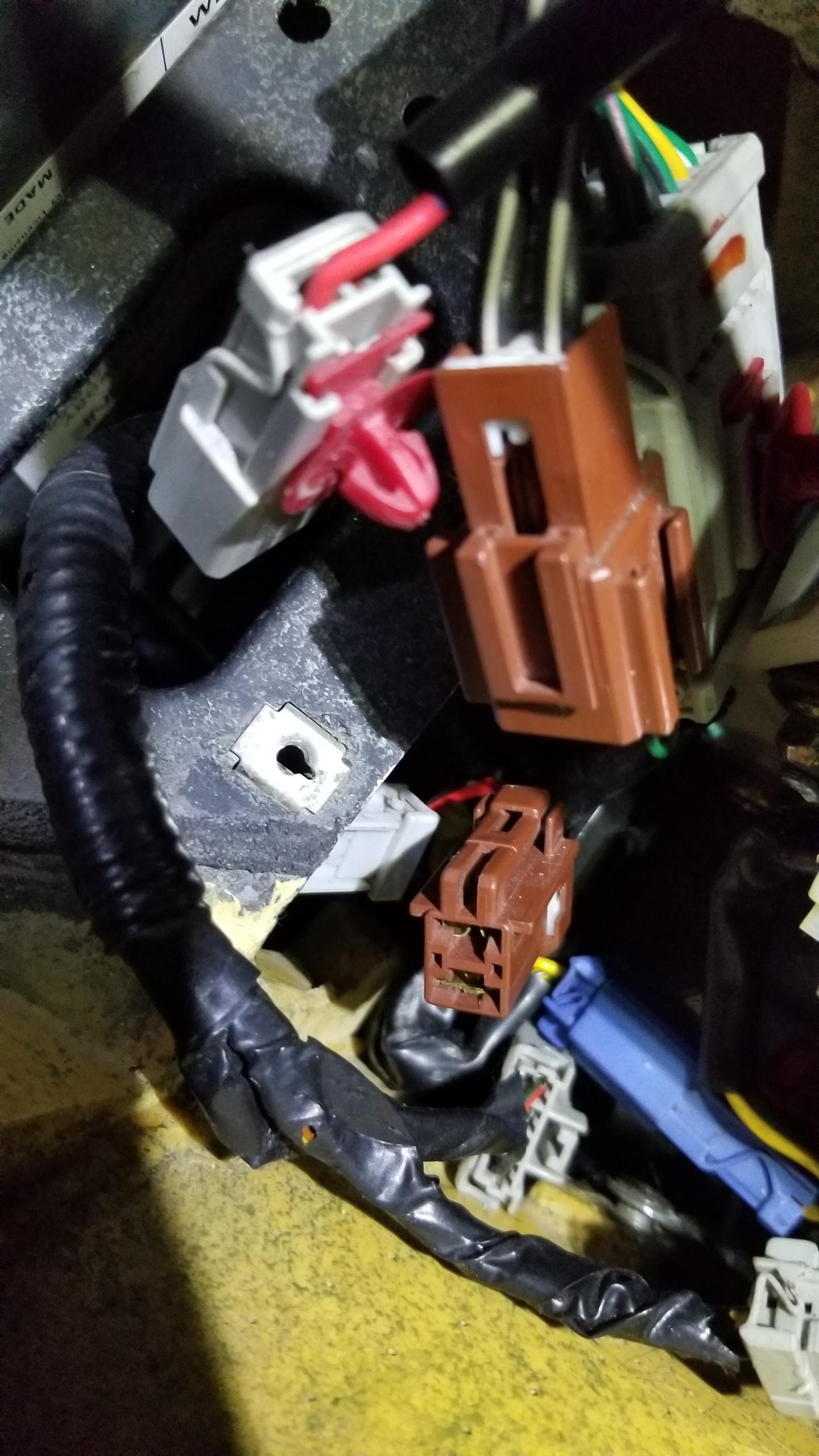
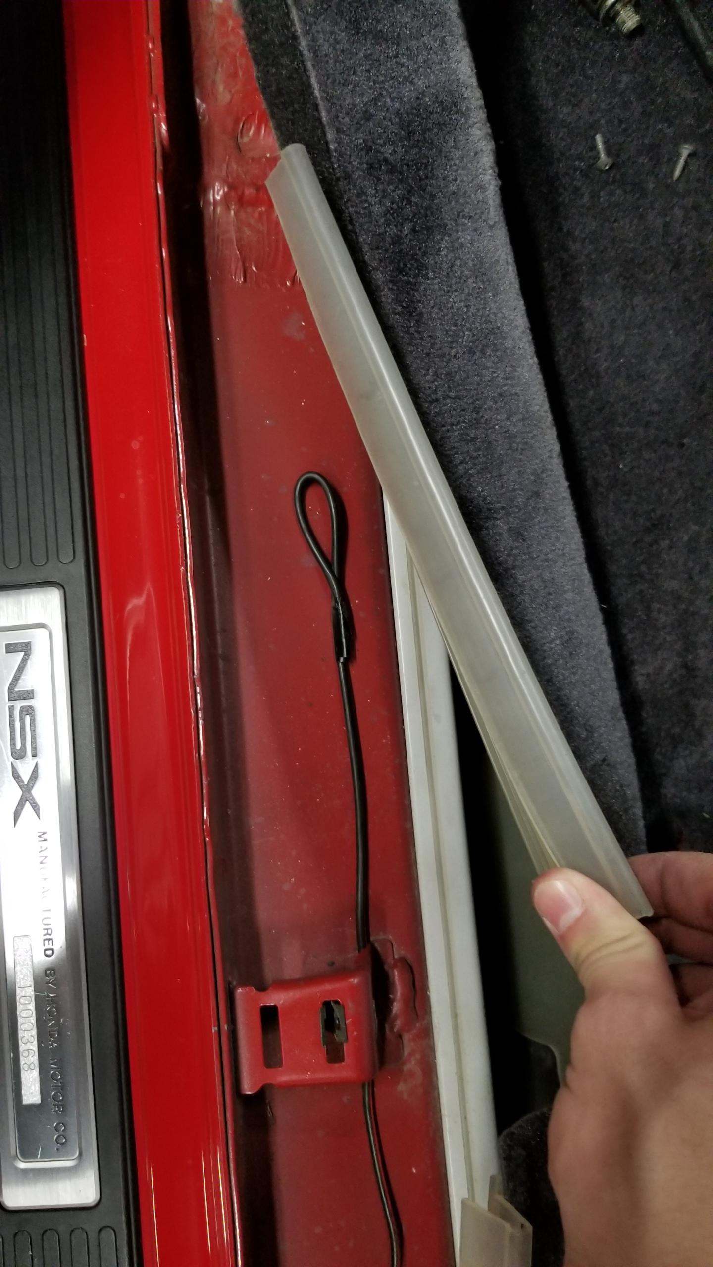
Here's where the other end of that random wire from my last post ended. Just a random unused wire. I took it out and threw it away.
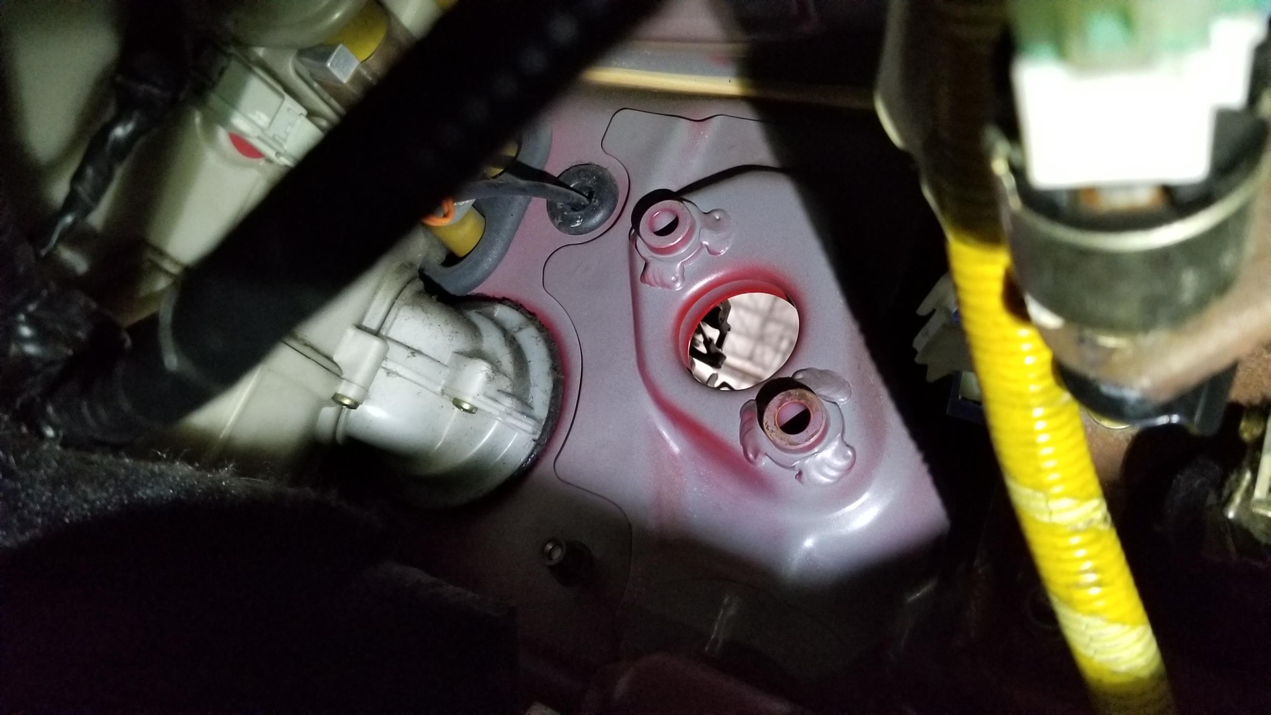
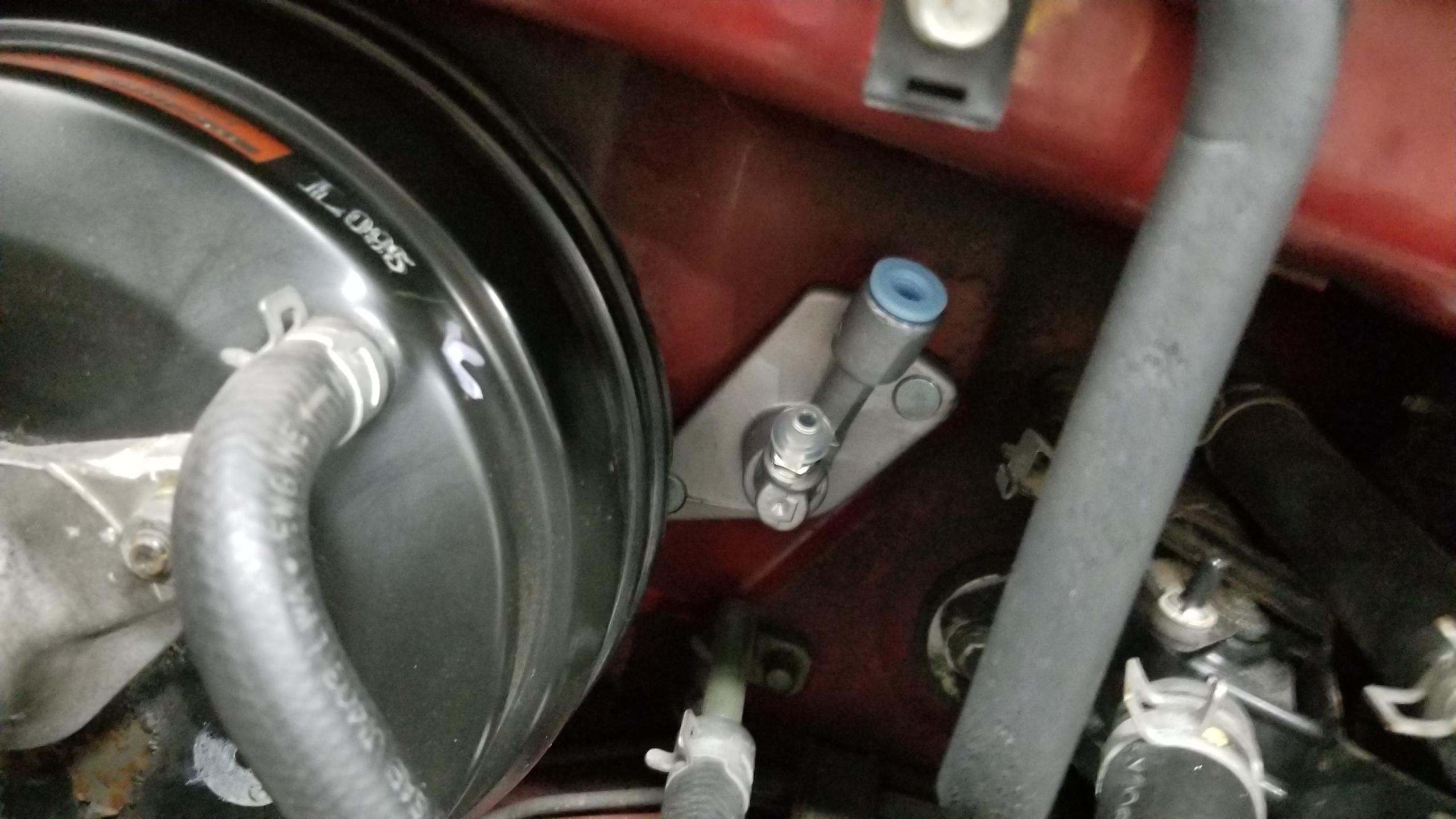
Beginning the clutch pedal install. Here's where the blanking plate for the master cylinder was. Two nuts removed and punch out the black seal on the frunk side. EZ
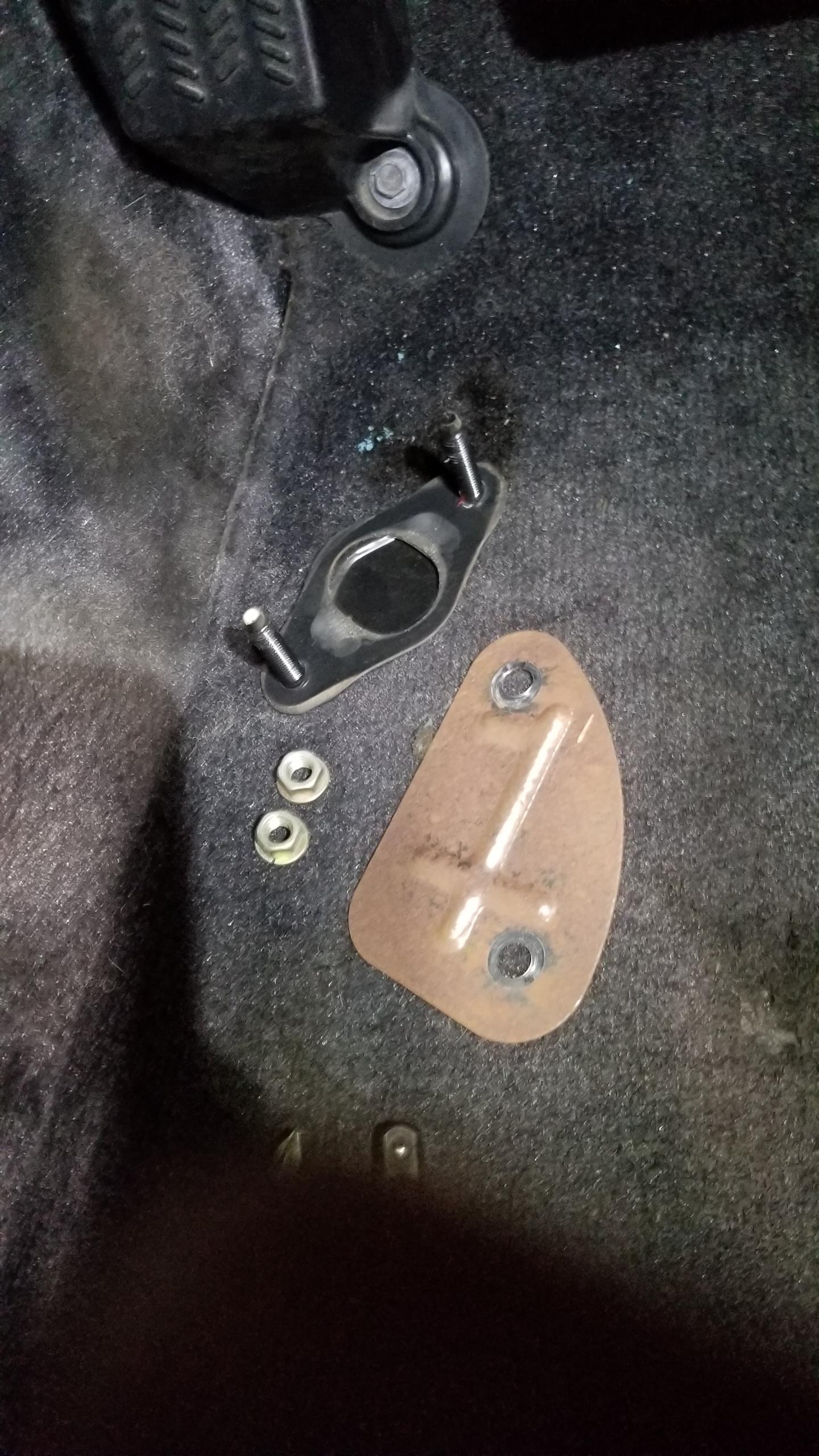
Blanking plate and seal w/studs. You can reuse the nuts for the master cylinder if you want.
Test fitting the pedal & bracket. Unfortunately it looks like the vestigial arm on the top for the unused second clutch switch hits the body at the top, so I wanted to cut it off to get more room.
Clutch pedal modified and spring installed. The spring can go on with no compression needed with the pedal all the way back. Friend and I fucked around with compressing the spring to get it in place for way too long before we figured out how to do it properly. Also, we got confused on the direction of the spring since there's no resistance on the pedal, so when you push it back, it springs back and gets stuck down. The clutch master is what provides the hydraulic pressure to push the pedal back in place so the pedal won't feel right until the lines are complete. TIL.
Clutch master pushed into place from the frunk. Simple. There's a rubber gasket that goes in between the master and the body, it's not included with the master.
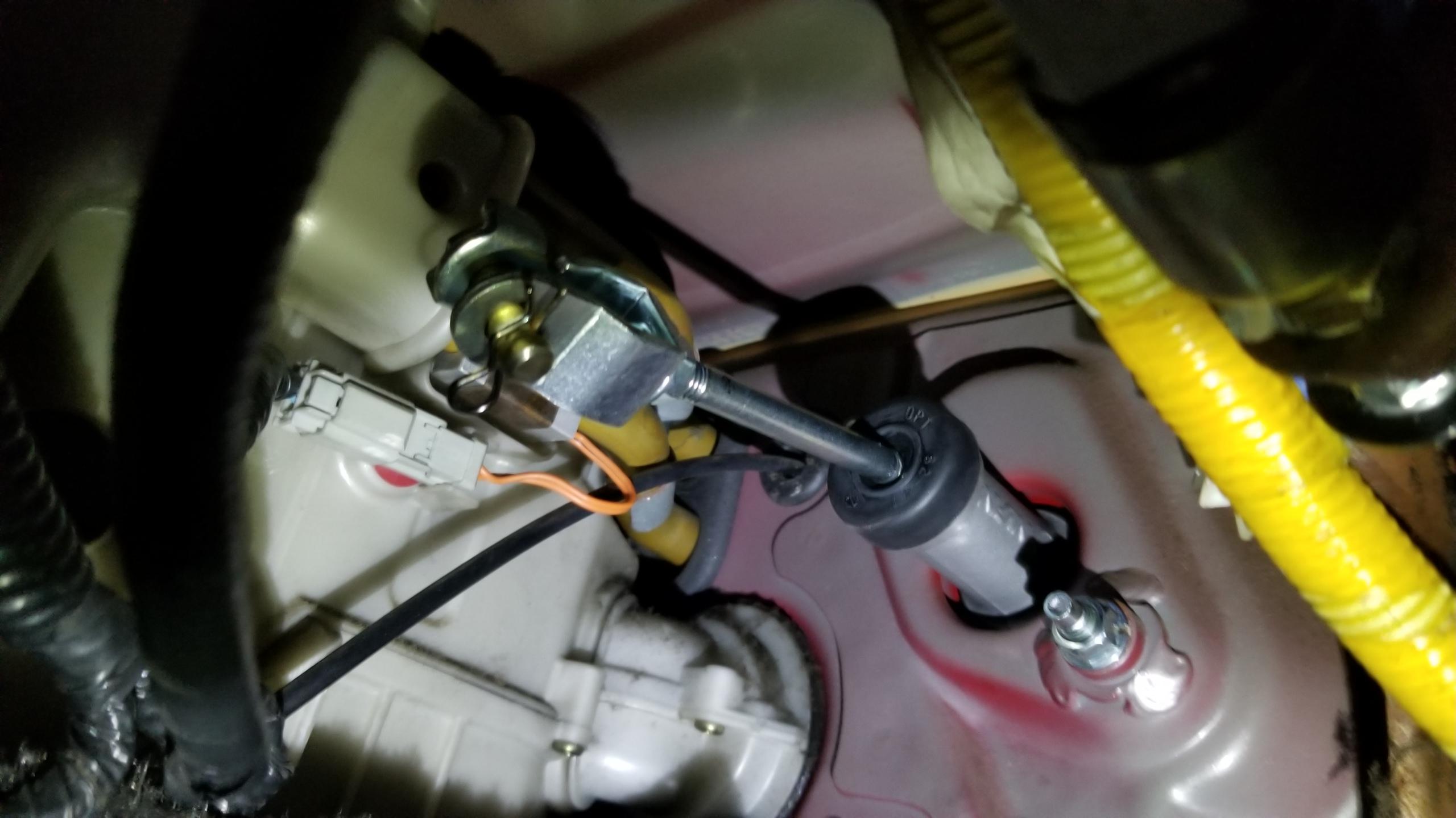
Here's what it looks like from inside. The nuts are supposed to go on after the bracket is in place, FYI. The pin & spring on the end will attach to the clutch pedal.
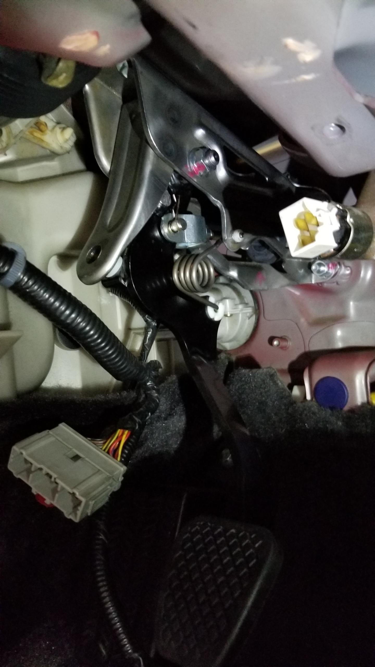
Pedal & bracket installed. Not too bad, two nuts on the master studs and one bolt at the top of the bracket into the upper dash. All factory bolt locations. Blue clutch stopped pad installed in the background. I haven't installed the clutch switch yet in the picture.
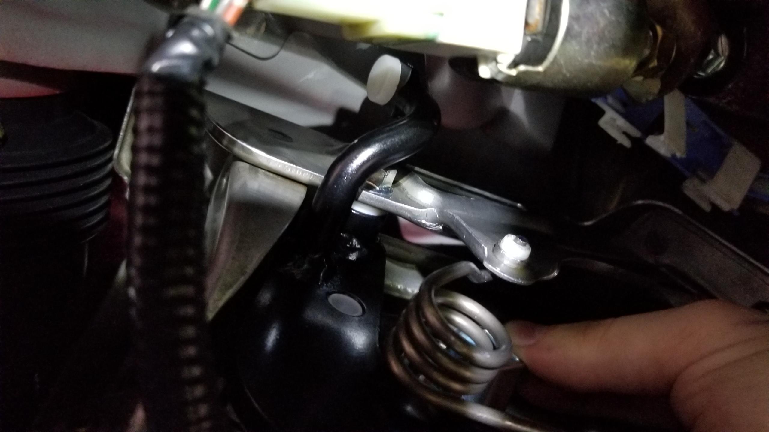
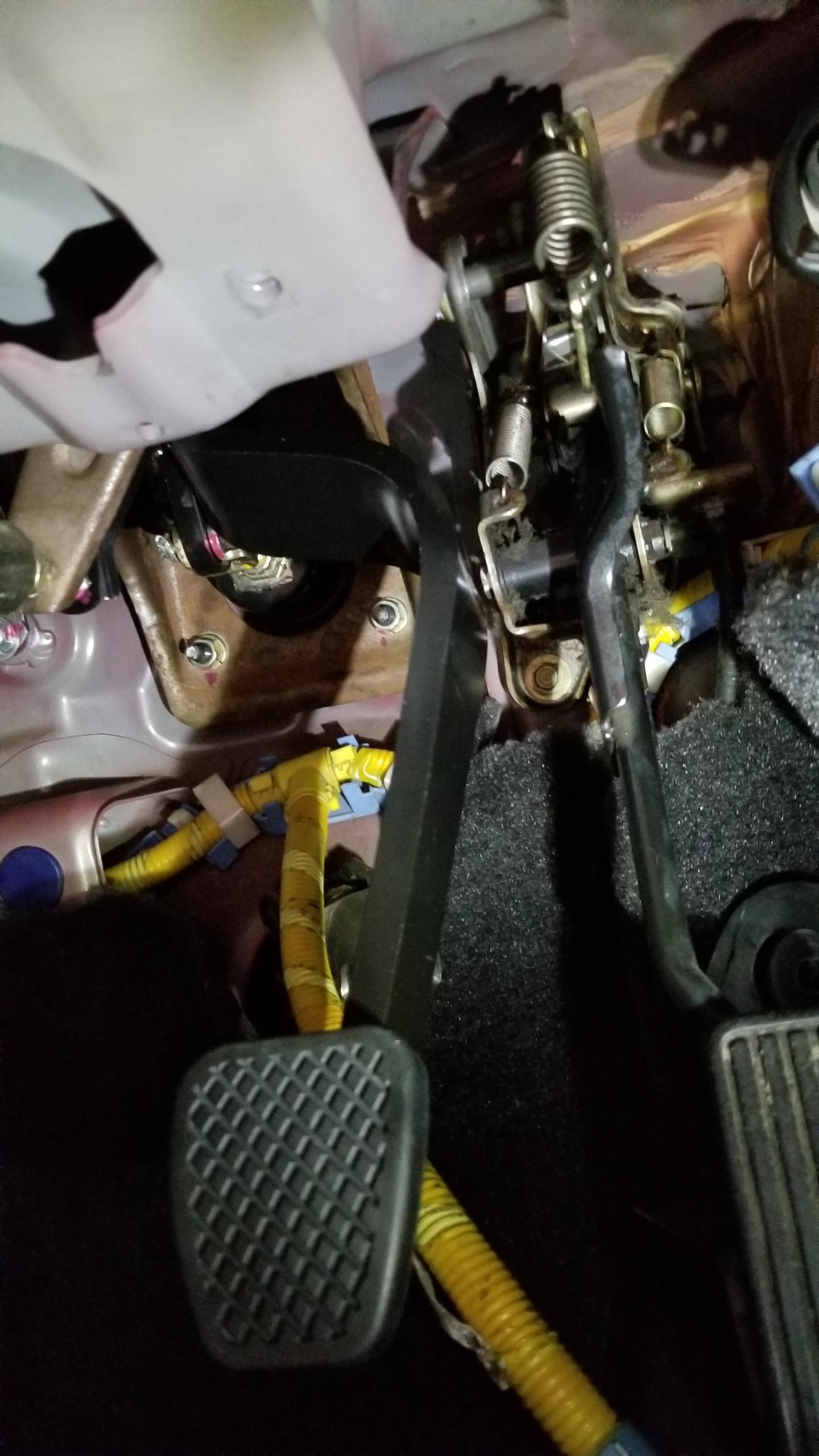
Now for the worst part so far by a long shot, removing the A/T brake pedal to replace it with the M/T version. This pic is actually after the install but I didn't get one of before. Basically, you can't remove the bracket without removing the master cylinder completely which would suck. You have to pull the master slightly to get the studs out of the bracket to get enough room to take out the through-bolt holding the pedal in, and the bolt was on super tight. Then there's a spring from the bracket to the pedal that has to be removed. This took like an hour just to take the pedal out. Suuuuucks.
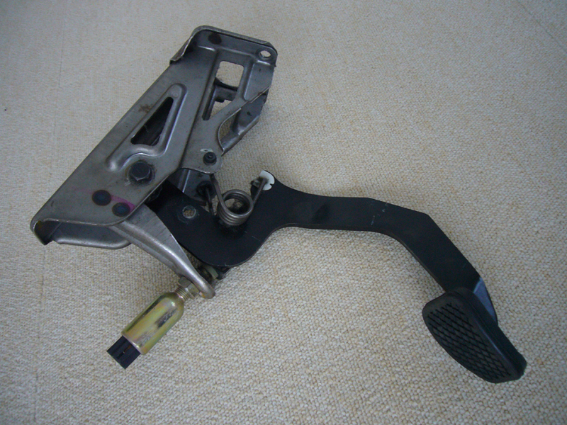
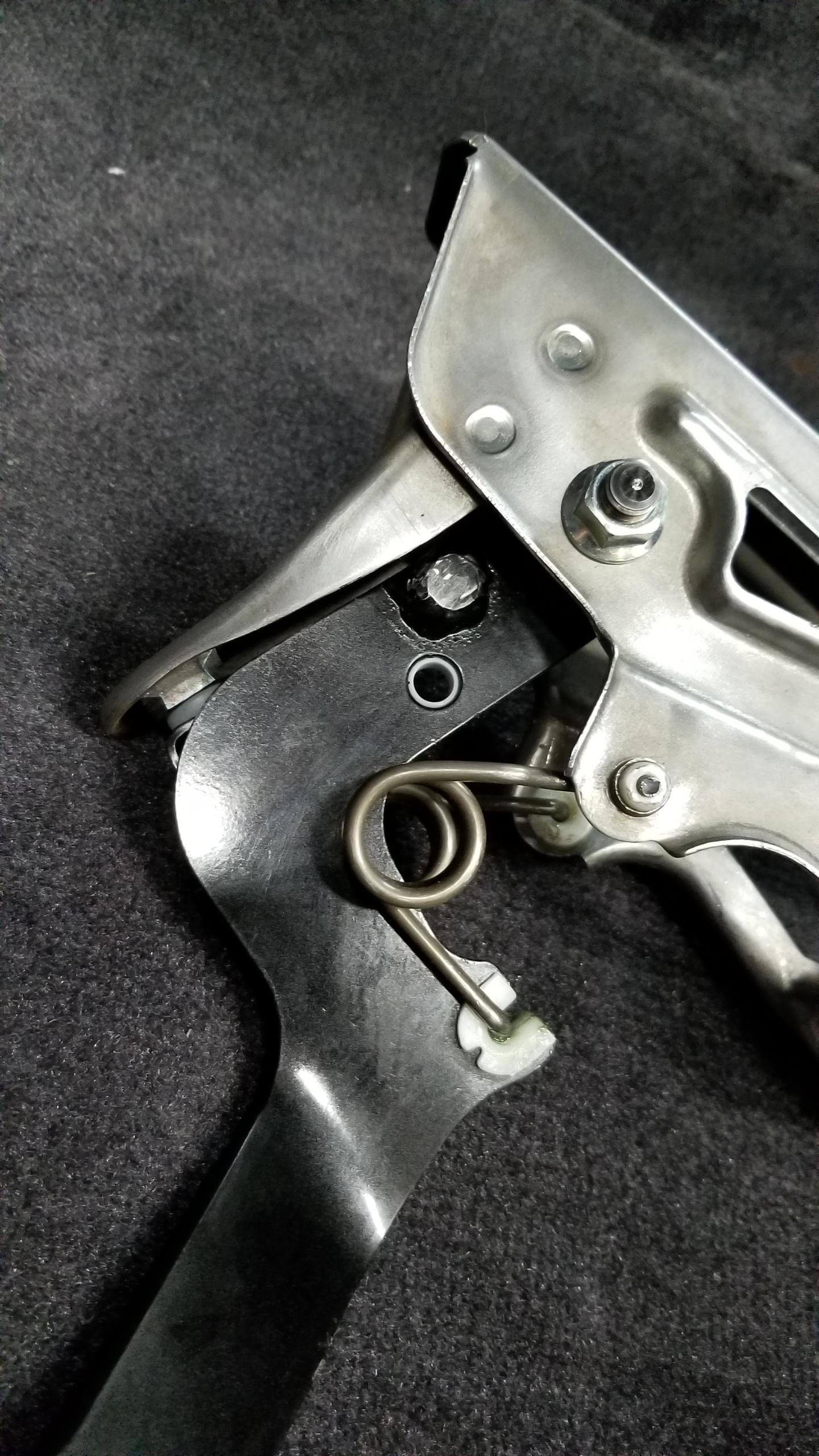
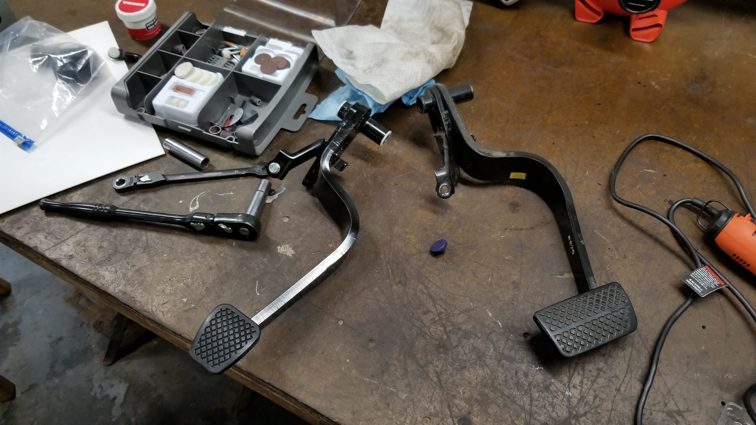
New and old brake pedal. Getting to this point was a massive pain in the ass. (I'm sure you'll see more of those before this is over). You can re-use the pedal collar for the new pedal, same size. I transferred over the bolt I used for the brake switch stopper.
New pedal installed. Putting it in is just as shitty as taking it off. The worst part is getting the spring back onto the new pedal, I had to use very long articulated needle nose pliers to grip the end of the spring and thread the needle onto the new pedal which took almost an hour by itself. Ultimately I'd love to take the whole brake pedal bracket out in the first place but didn't want to mess with the master cylinder and remove it or bleed brake fluid. Oh well, it's installed now.
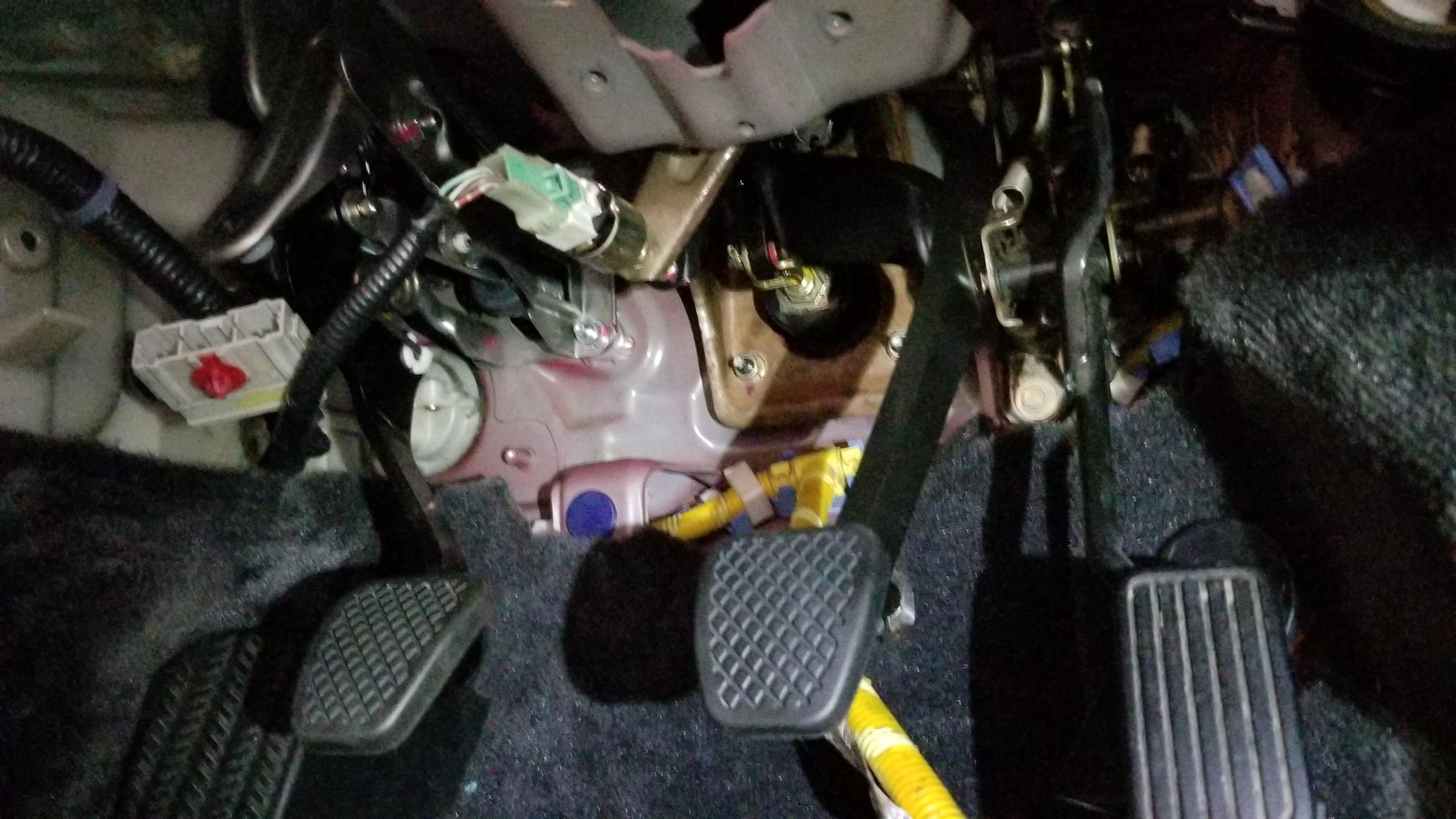
Three happy pedals. I have not adjusted the free play for the clutch or brake pedals yet but will do that towards the end of the project. I don't believe the brake should need to be adjusted. (or rather, I hope not).
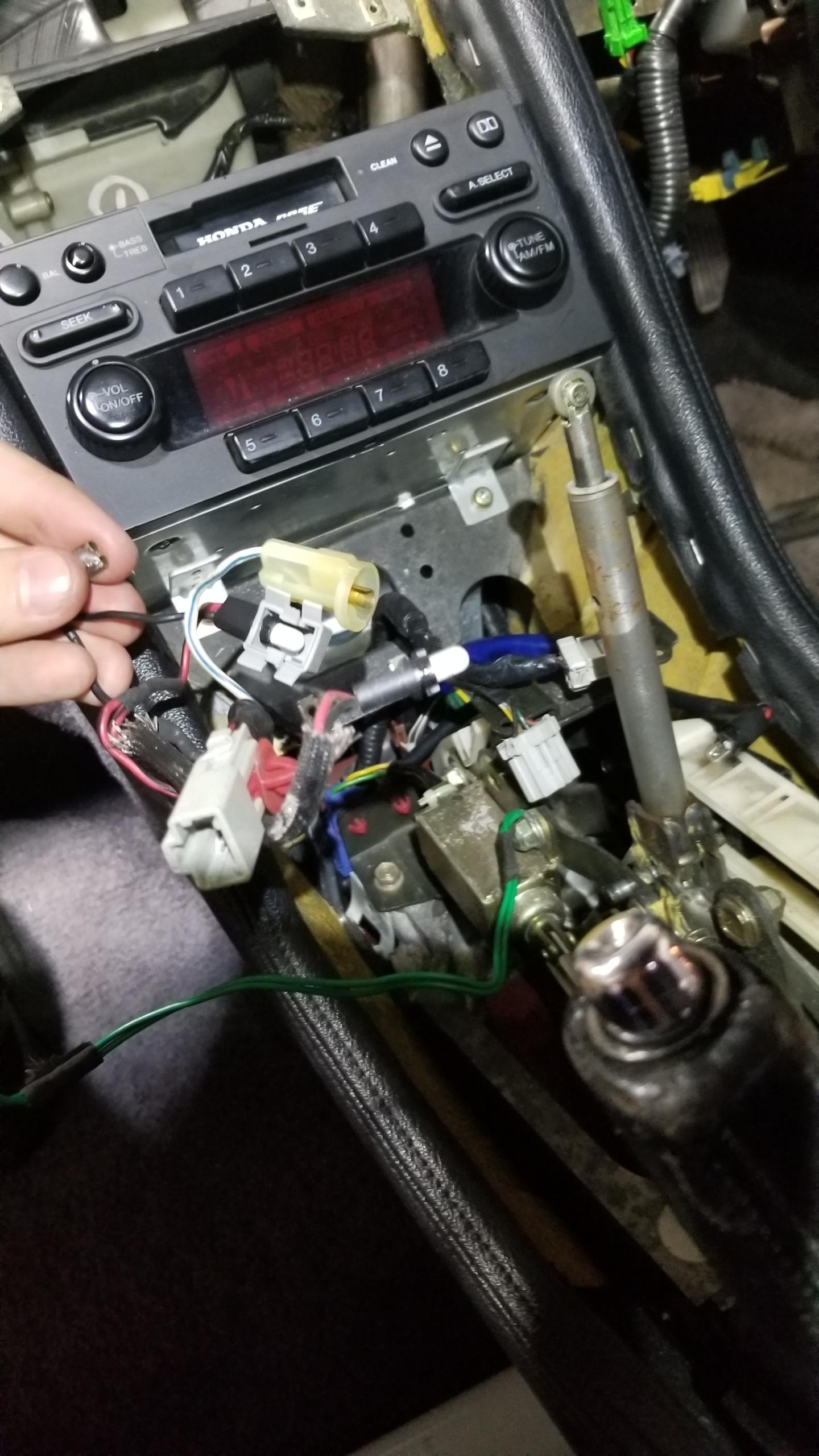
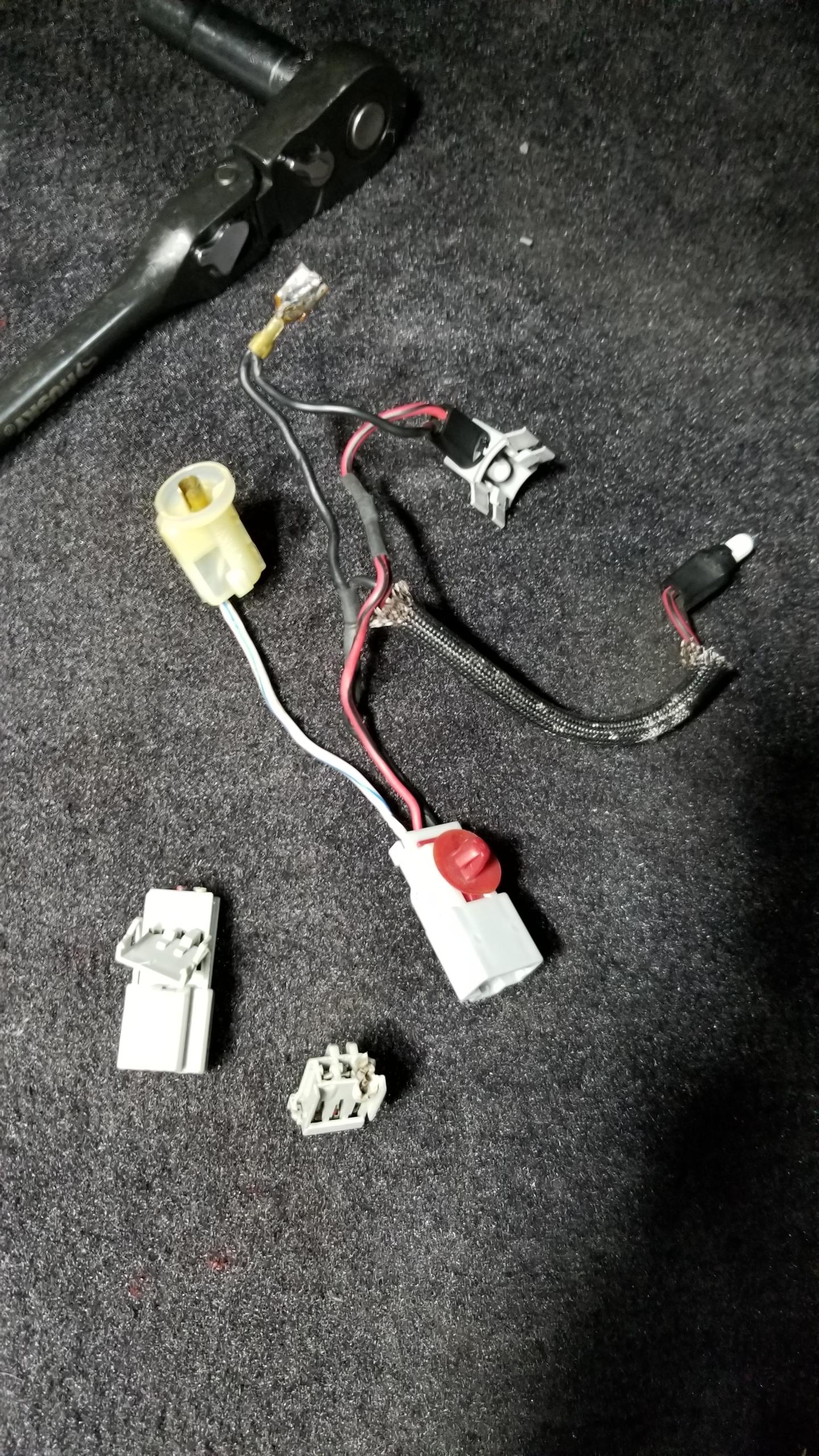
Time for some wiring. I took some time and fixed the cigar lighter harness from my previous post since it was messed up. I used an OEM 3P terminal, cut off the old one, and crimped on the new terminal. Good as new.
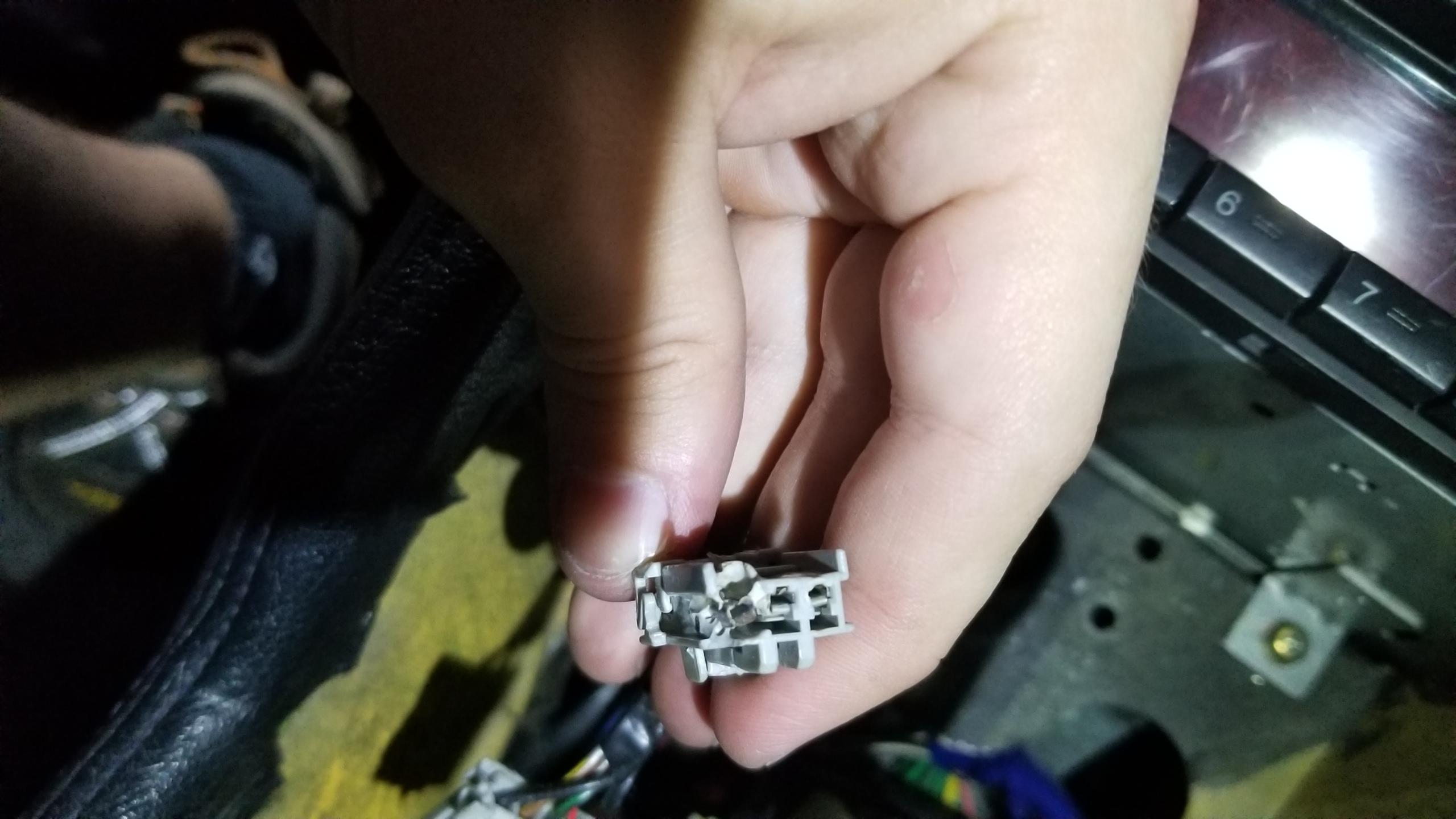
Fixed the male side of the harness with a new connector and terminals. Two old ones I cut off on the bottom. Hopefully there's nothing else wrong with the circuit besides this.
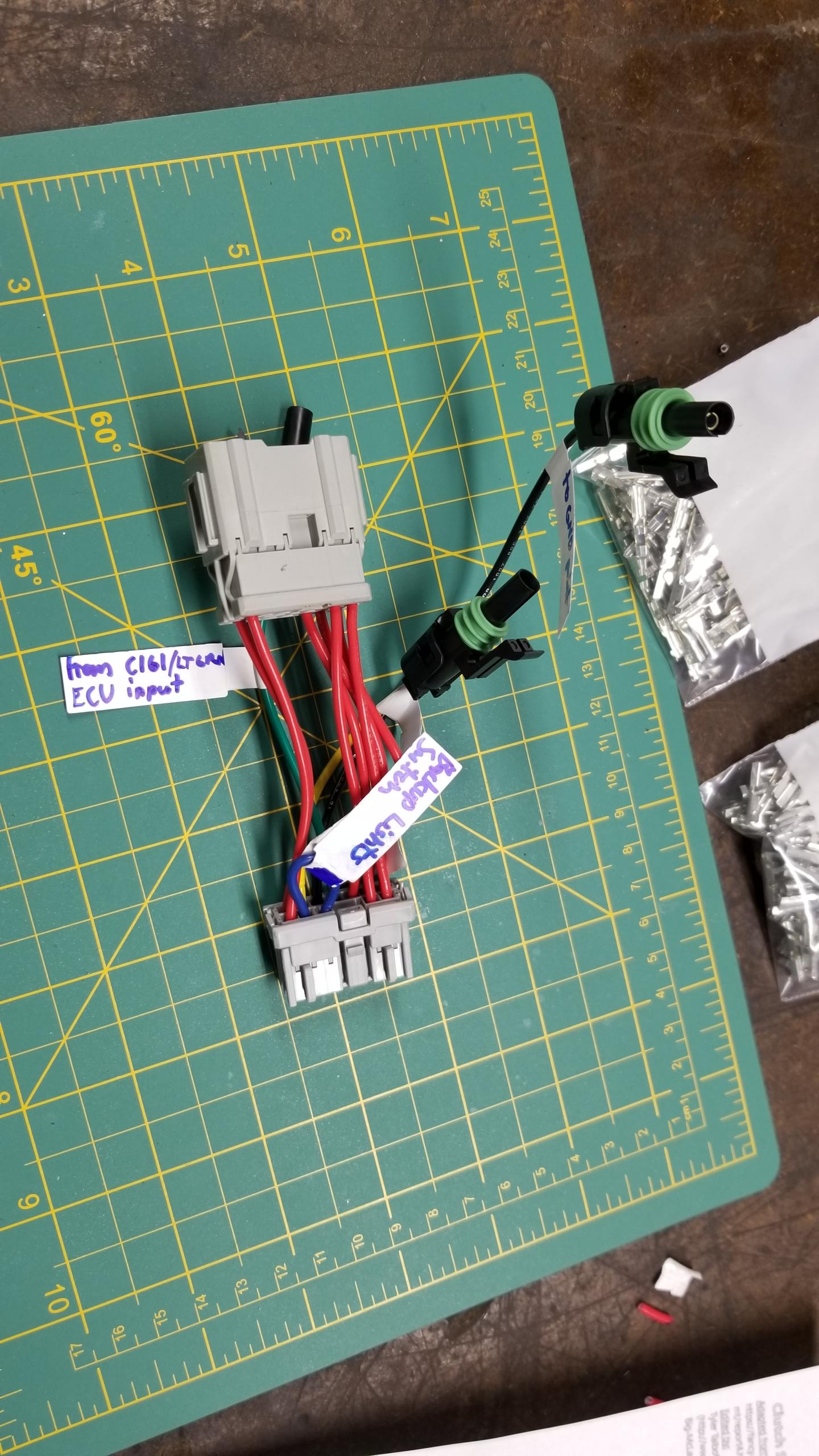
First major patch harness in progress. I'd never crimped my own terminals or made a harness before so this is a learning experience. I practiced with a few terminals before doing these final connections. I'll post my modifications of the FancyCraft wiring diagrams here (
https://fancy-craft.firebaseapp.com/NSX/report/at-mt/report4.htm) but I need to make some updates from some mistakes with my markups.
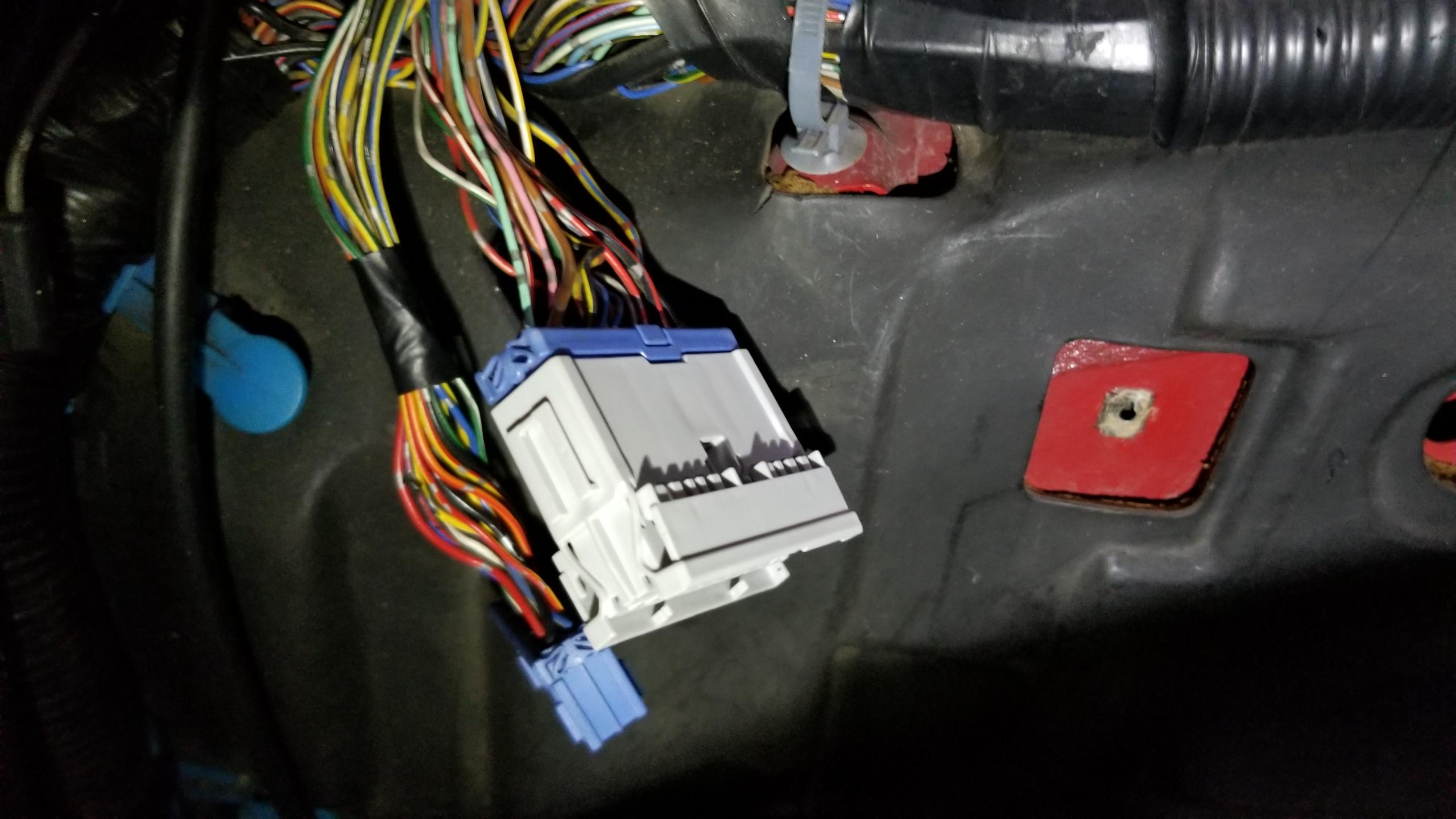
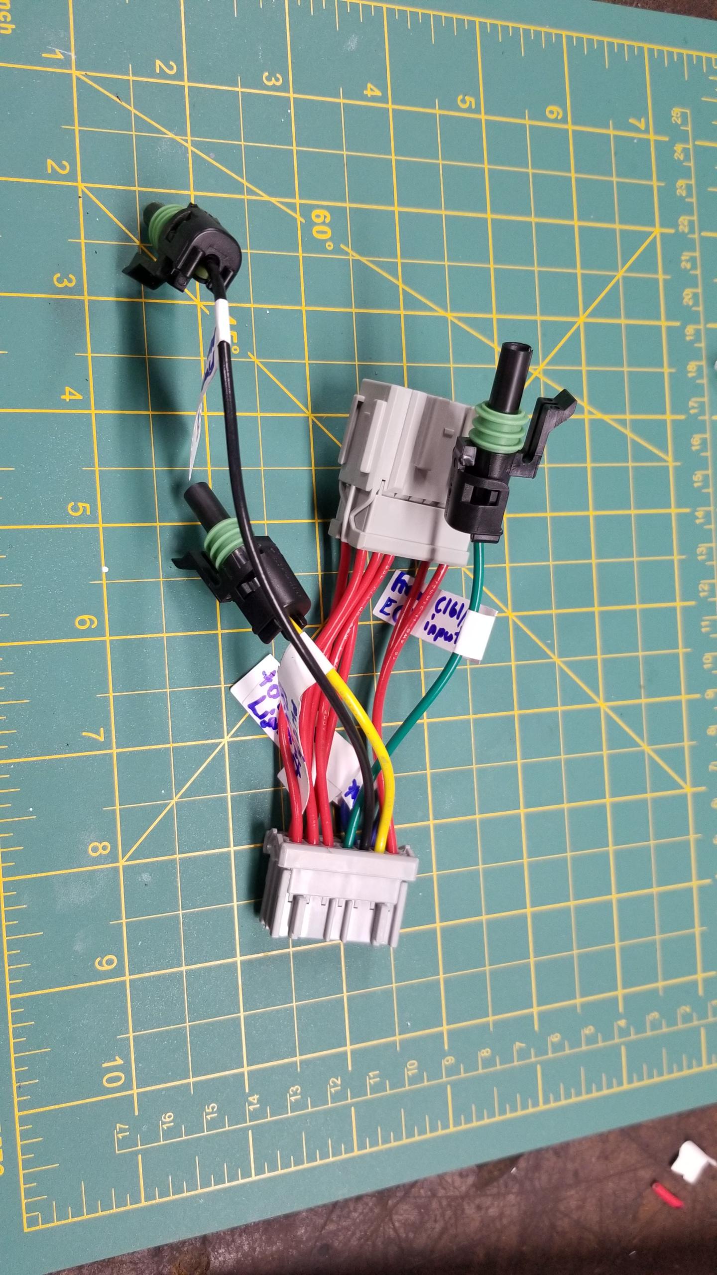
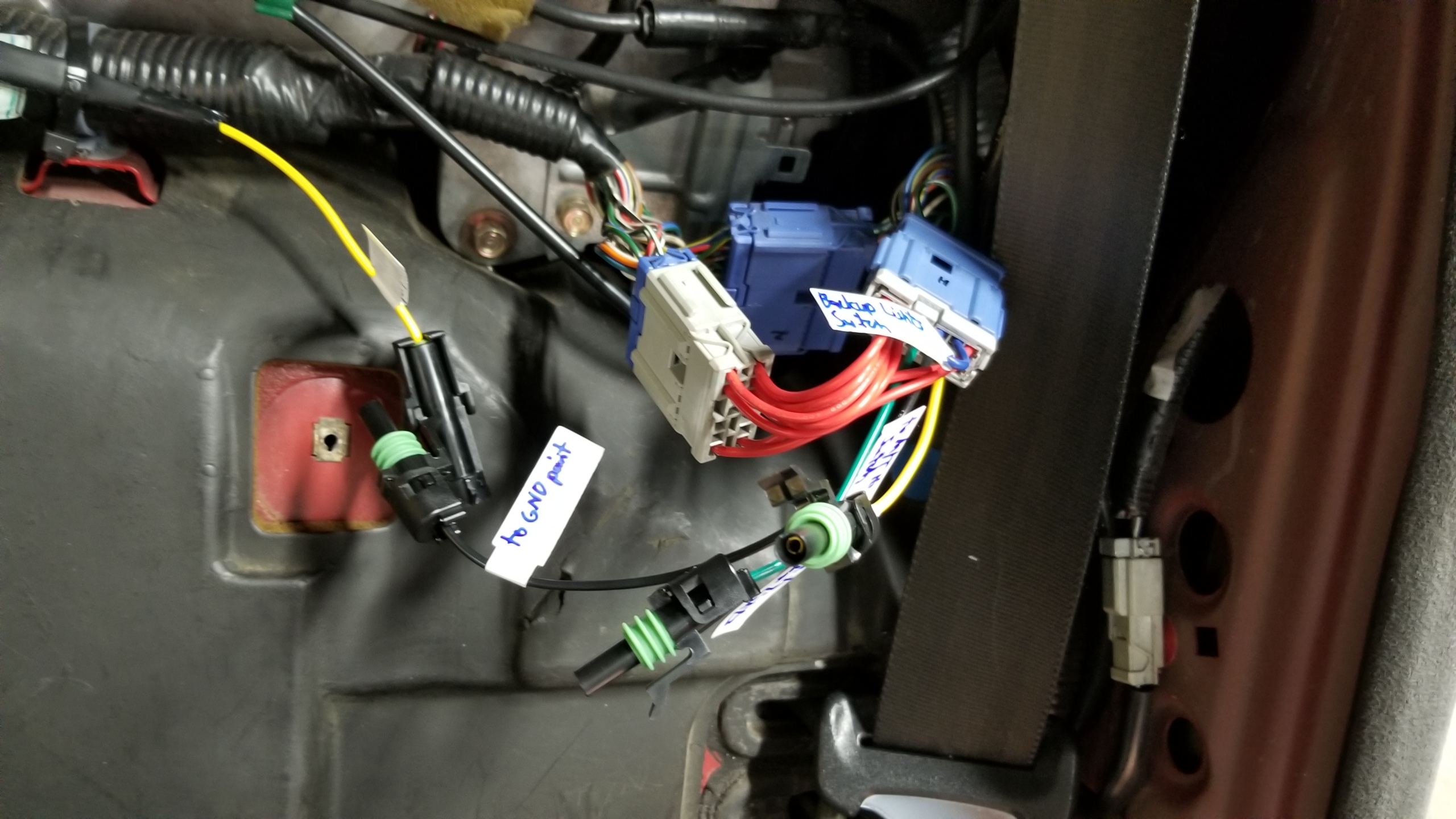
This harness will be for C499 which is on the passenger (left) rear side of the firewall. This will mostly be used to wire in the backup lights and backup light switch and connect it to the YLW power line. The single-pin weatherpack connectors are from another kit I bought, not Honda OEM but work perfectly fine. I didn't have the proper Honda connectors for those lines, these weatherpacks are overkill for these interior harnesses but it's what I had on hand. I also could've used one 3-4P connector instead of 3 separate connectors but this was more of an iterative process than something I planned.
Other side of the patch harness. Red wires just connect the original male to female pins to keep the same function. Yellow wire sends power to the backup lights. This connects to the yellow wire on C425 on the shift console switch, which normally sends power to the shifter itself but that function is no longer needed, so I re-routed the power from the connector to the lights instead.
Black wire is to ground for the ECU neutral switch input. Green connects the ECU neutral switch input to the M/T neutral switch on the trans. The blue jumper wire ties together the backup lights to the backup light switch on the trans. I think this should work well.
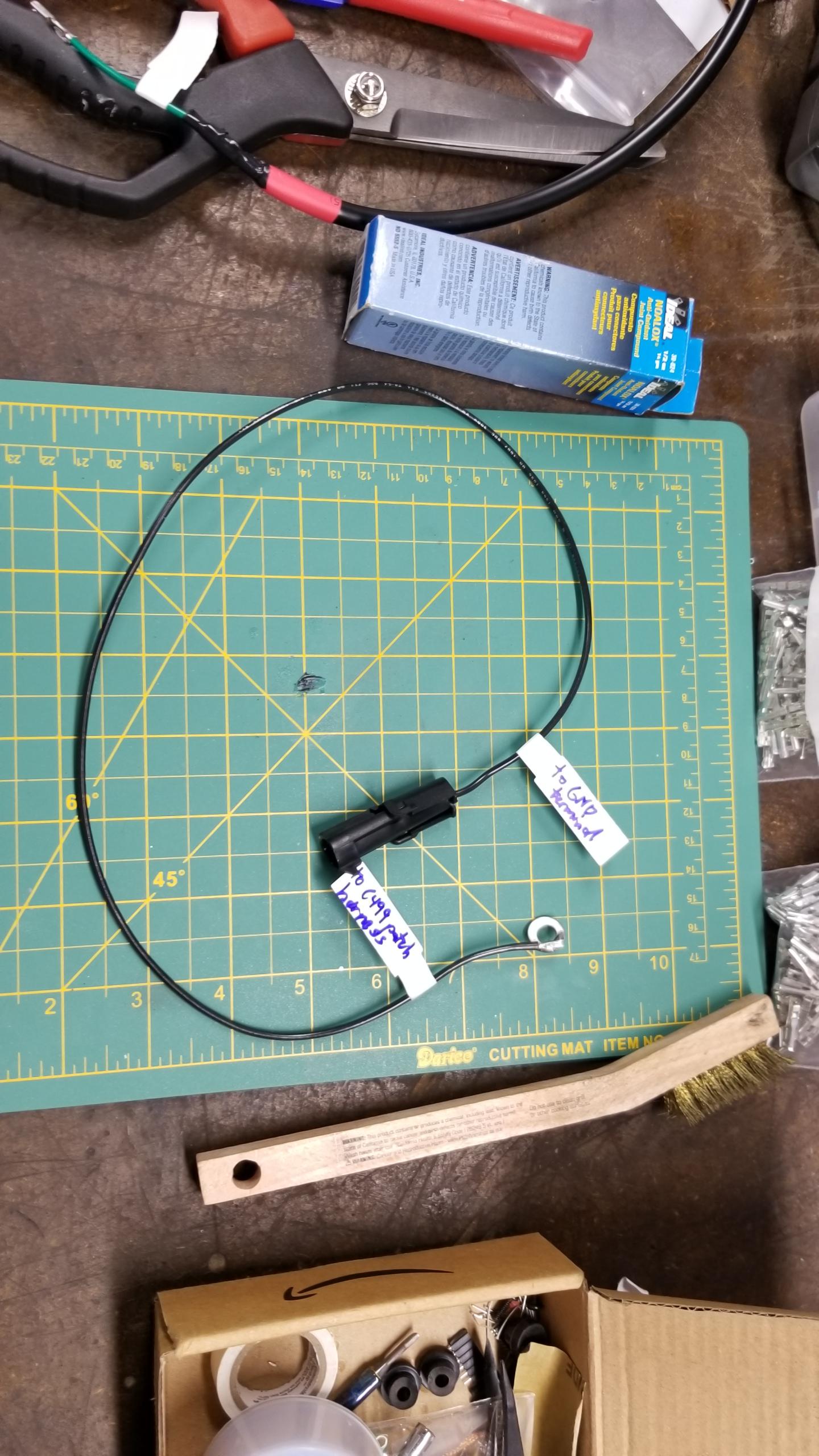
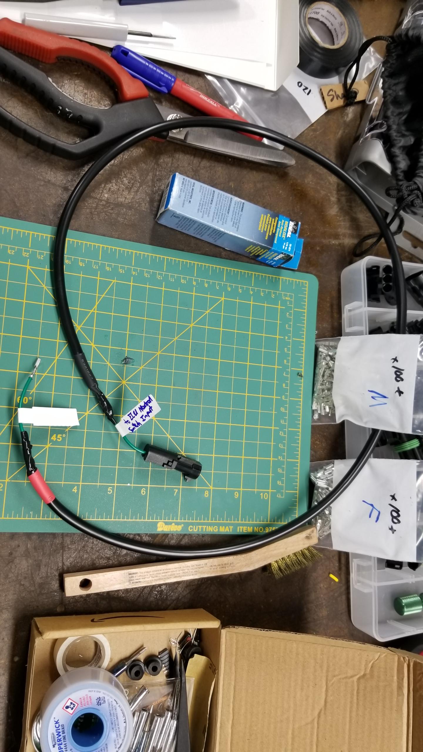
Here's the other end of the ground harness for the neutral switch. It connects to a factory ground in the middle of the firewall.
Here's the "harness" for the ECU neutral switch. I could use normal connectors on both ends instead of an OEM female terminal on one end but this will work fine. (i.e. I'm not that good at thinking ahead).
Test install of the patch harness. Zero modifications to the factory wiring, fully reversible, all the new connections are labeled. I'd like to think this is a decent try at a proper wiring job. The original blue connectors still go into their factory spots.
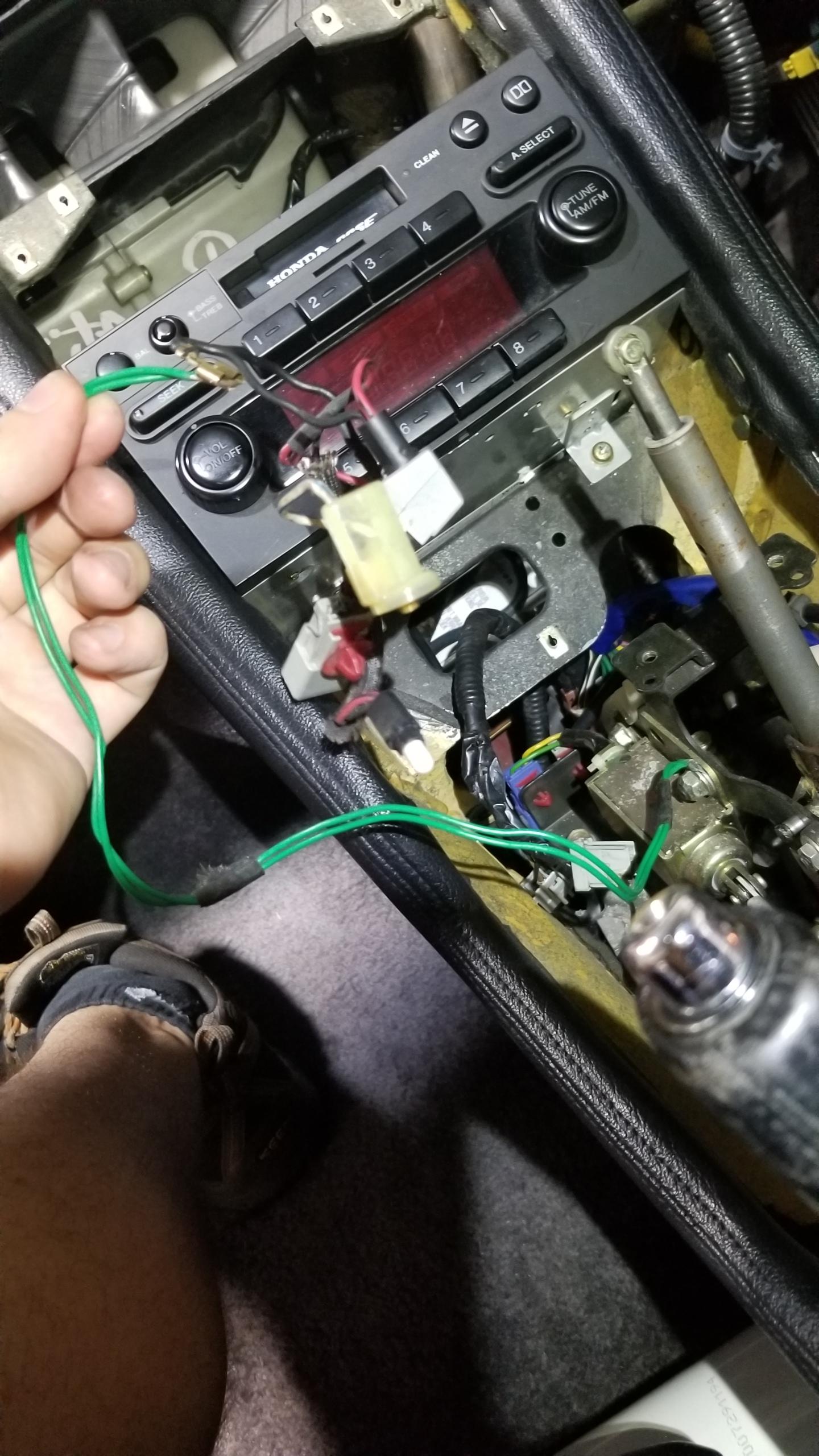
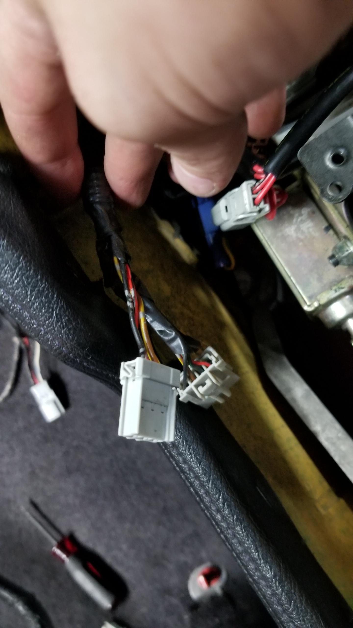
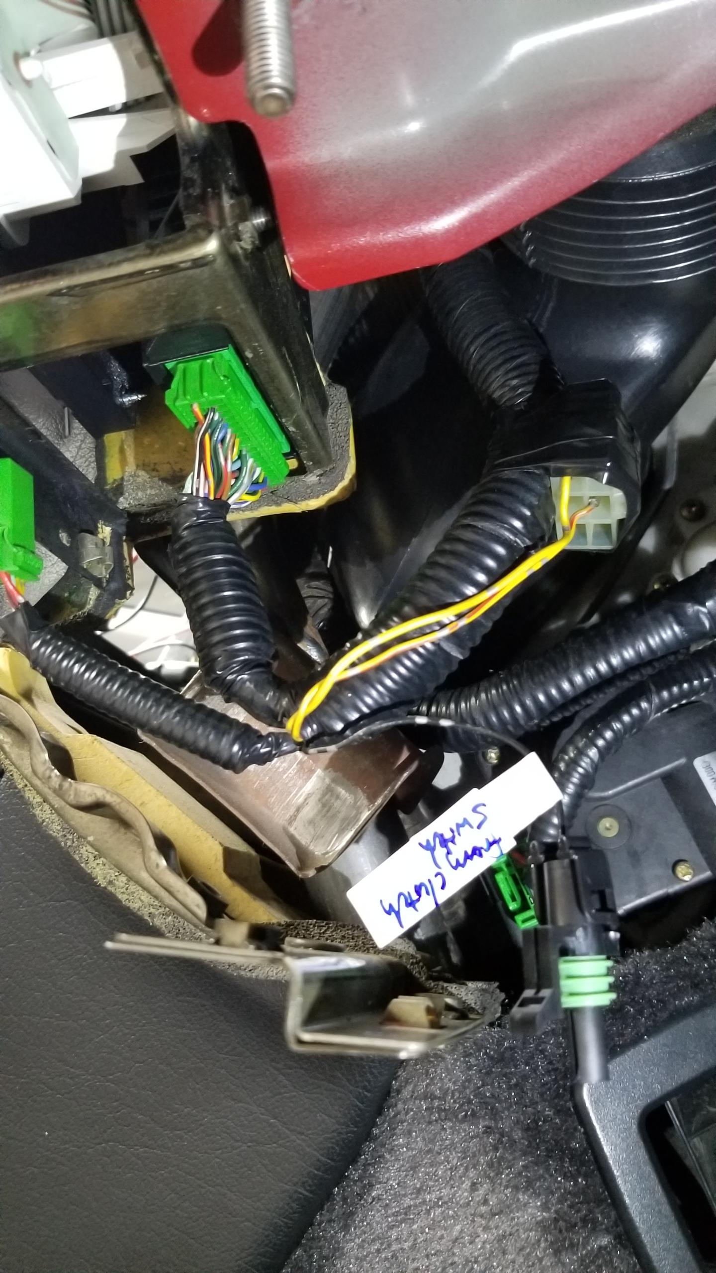
Last thing I got to this day was starting the clutch switch wiring. Step one is finding a ground point for the switch. I didn't see a factory point nearby, but there's this connector just taped to the gauge cluster harness not being used. I'm not sure what it's for, maybe an option feature not being used. It had a black wire which I confirmed was a factory ground wire with a multimeter to various other GND points on the car. I de-pinned the terminal and put a new 1P weatherpack connector on which just needs a short 6" harness to the clutch switch which is just to the right of the pic. So far this is the only real modification to the factory harnesses, but it wasn't being used for anything else anyways.
That's it for today. The wiring is interesting but a little tedious, so it takes longer than I'd think. I'm working on finishing the wiring today, the only remaining work is the 3P clutch switch and the C425 shift console which shouldn't be too bad. Other goals for today is installing the shifter assembly, maybe putting the seats back in, and removing the drive axles if I manage to get that far (might be wishful thinking

). In any case, most of the interior work will be done today.
All this is also based on the SoS clutch kit supposed to arrive on Tuesday. There were more supplier delays, so I had to pay the extra $140 for overnight shipping to get the kit by early this week. As long as there's no other delays (which there shouldn't be...) then I should have it in time for when I need to start putting parts back on the car. I already planned my whole month around taking this week off so I wasn't going to postpone this again.
I'll try to post day-by-day but I tend to work late into the night so there might be a few days in-between updates.

