-
Protip: Profile posts are public! Use Conversations to message other members privately. Everyone can see the content of a profile post.
You are using an out of date browser. It may not display this or other websites correctly.
You should upgrade or use an alternative browser.
You should upgrade or use an alternative browser.
Intake manifold information
- Thread starter A.S. Motorsport
- Start date

Looks really nice, can we get a shot with it upright?
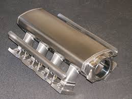
Here is a quick pic. Keep in mind this is for general design and fitment purposes. The next version will have a better finish


Looks like one of the old "tunnel rams" from back in the day.
Nice work.
Damn, that looks like a fundamentally good design. If you get the diameter, taper, length, and angle of the runners right, the shape of the bellmouths, the orientation of the injectors, the cross section of the intake plenum at its entrance and at its back wall, etc., that looks like it should allow for some seriously efficient high rpm breathing. If that fits under a stock engine cover, I'll seriously consider buying it.
I also like Nero Tenebre's and Honcho's suggestion of being able to give it an OEM look, for customers so inclined. If the OEM intake manifold top plate makes the manifold too high to fit under the engine cover or if the threaded fittings have to stick into the plenum where they would disturb the airflow, maybe simply mounting part number 12510-PRB-A00 to the top of the plenum could be a solution - that's the OEM Acura emblem from a 2005 NSX intake manifold top plate.
I also like Nero Tenebre's and Honcho's suggestion of being able to give it an OEM look, for customers so inclined. If the OEM intake manifold top plate makes the manifold too high to fit under the engine cover or if the threaded fittings have to stick into the plenum where they would disturb the airflow, maybe simply mounting part number 12510-PRB-A00 to the top of the plenum could be a solution - that's the OEM Acura emblem from a 2005 NSX intake manifold top plate.
If it gets the greenberet stamp of approval you know you've done something right, I don't think anyone on prime knows the details of the oem system as well. I would say forget the oem emblem on it only because this can be added by the end user with 3M tape (those that want to use a different logo or decal won't be restricted). I might be inclined to write out Honda on it considering the size of it.

I was just thinking use the "Honda Motor Co." plate (or the Acura "A" plate for newer cars), not the entire top manifold cover. Just cast a shallow recess into the top with two threaded holes. Should not affect displacement.
IMHO I don't think the size of this manifold would look good with the scale of the NSX plates. Plus those parts are expensive when you can just add a decal or emblem on top of the design as is for maximum versatility, ease of construction, and ease of volume calculation and probably better performance. Either way it's probably too early to tell... But after seeing it there's no way it will go unnoticed like the oem setup- which I think is a good thing.
Last edited:


Am I the only that thinks this...Here is a quick pic. Keep in mind this is for general design and fitment purposes. The next version will have a better finish
")

I was thinking of something like this too.
Or this;
Or this;
looking good! what size diameter will the runners be?
Is this a diagram from Honda? It appears so but the flow through the "highspeed"/open VVIS plate does not seem to be correct. As air enters the intake manifold, it does not go through the butterflies into the lower plenum before being sucked up through the runner on the other side
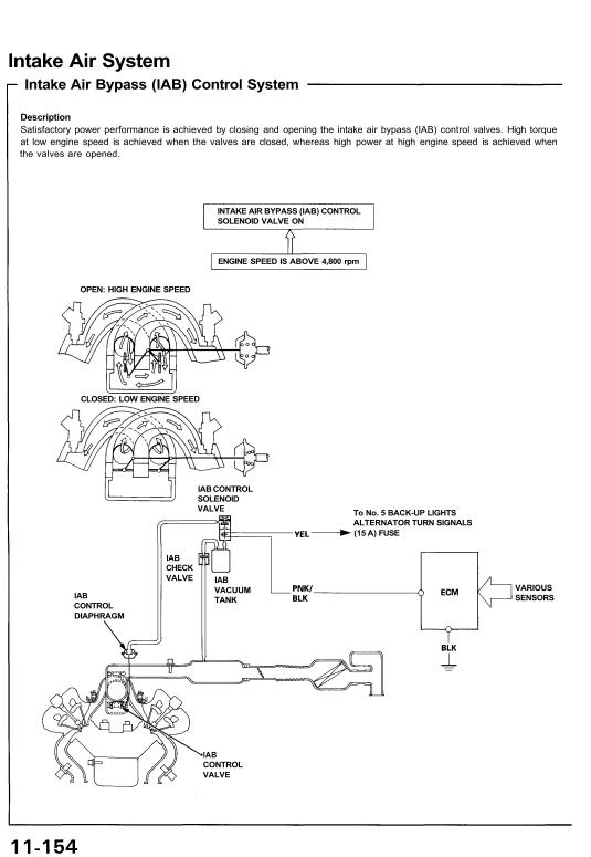
BECAUSE: There are 6 butterflies and 6 runners (6-cyl) and the butterflies are located directly above the opening for the plenum. As the engine is sucking air into the runner, air comes from the throttle body and seeks the path of least resistance -directly into the runner, it will not flow down through the butterflies, back up through the opposing butterflies into the opposing runner.
Is this a diagram from Honda? It appears so but the flow through the "highspeed"/open VVIS plate does not seem to be correct. As air enters the intake manifold, it does not go through the butterflies into the lower plenum before being sucked up through the runner on the other side
BECAUSE: There are 6 butterflies and 6 runners (6-cyl) and the butterflies are located directly above the opening for the plenum. As the engine is sucking air into the runner, air comes from the throttle body and seeks the path of least resistance -directly into the runner, it will not flow down through the butterflies, back up through the opposing butterflies into the opposing runner.
Yes, that is a page straight out of the service manual. While I am not totally sure on the nature of the VVIS system, the air won't always take the path of least resistance or else aerodynamicists would be out of jobs :tongue:. It is likely that there will be flow through the lower plenum. Someone at Honda had to write a report/justification study on this else it wouldn't be put on their flagship supercar, I'm sure.
All this being said, I personally do not quite know enough about how/why the VVIS behaves the way it does.
Lucas
Thanks for the input. However, I am able to get my desired plenum volume for the NA application manifold with the factory cover. It will need spaced up 1/4 of an inch though and spacers will be supplied. I am making another version for outright HP that will be a little bigger and the engine cover will have to come off for that one.
- - - Updated - - -
As stated above, there will be a manifold option that will allow for the factory cover. The manifold will be optimized as much as possible in all categories, and by the design alone will provide more hp than originally thought. The FI model will take advantage of the large amount off space above the factory cover to provide the volume needed for the buyer wanting large HP numbers and a very broad high rpm powerband. The runners do match the angle of entry to the cylinder head, and the head flanges will be shaped accordingly to prevent the "z" shape you are referring to. I am even looking into making a matched set of billet fuel rails to accompany the manifold to complete the package.
i'm going to cheat by coming out last. =) on a seriously note i do not like compromises when it comes to NA parts design unless the compromise is absolutely necessary. if we (AKMEE) do it you guys will have to toss the engine cover. no if's and no but's. i no care if you want engine cover.
Thanks! You did a great job sketching to give us a visual! I am actually finishing up my manifold I will be testing within the next month. I will have stock vs. my modified manifold so we can see some solid differences in design. From testing we have confirmed that on a NA NSX keeping the VVIS is essential to insure low to mid range power. On a turbo we have picked up power eliminating it and using one of our Plenum spacers. I'll post up my findings soon.
To all those interested in my versions of the manifold. I have finished the prototype and I should have a finalized version in a couple of weeks. I have calculated the finalized plenum volume to be very close to 7.2L with the engine cover (spaced 1/8 inch in front)give or take of course. It will support any type of NA application as long as you don't just run only the manifold. I am assuming everyone who buys this will have some supporting mods so my dyno testing will reflect that (ex. headers, exhaust, and some form of tuning). Since the parts I have produced for my NA1 have already depleted the fuel delivery system I suggest everyone who installs this to upgrade the fuel system including the injectors. This manifold size is enough to support an engine making almost 200 percent VE naturally aspirated. Since the C30 and C32 engines will never surpass that it will never be a restriction. Even at the engine's biggest displacement this manifold will only produce more power. It can cover just about every forced induction setup as well. I have built turbo setups on 4 cylinders with intake manifolds in the 5.5L range making close to 1000BHP so this manifold will more than suffice a FI application as well. On the NSXs with throttle cable it will accommodate a BLOX Honda 76MM throttle body and for the DBW guys there will be a throttle adapter flange to accommodate the factory throttle body. If anyone wants to run my AEM Infinity PNP setup I can handle the task of getting you a bigger DBW throttle body that will work too.
Despite the manifold having some versatility, I will still make a bigger volume version of this as well. It will accommodate only a 90MM throttle body( I have not chosen the type yet) and the plenum volume will be roughly 9L. This is for outright HP (more than 1000whp) and high rpm operation. I will start on this manifold after the smaller one is done and I am satisfied with it.
To those who know what they are looking at you will see some sneakiness in the design but I am trying not to go overboard until I test the first one
The manifold will be all aluminum, probably brushed and/or polished. I have tucked everything underneath it (sensors, throttle cable, vacuum ports) to make it the centerpiece of attention and most importantly clean. So far it only weighs in at 14lbs (stock with TB 34lbs) but I will weigh it in when it is done. I will post a teaser shot of the rough prototype if anyone is interested in seeing it at the early stages. I have so much more to tell but in due time. If anyone has any reasonable questions please don't hesitate to ask.
That's a good question, but I'm sure you know the advantages/disadvantages of both setups. Personally, If I were doing a full NA build I would contact Kinsler to make my ITBs. The Toda and SOS are nice units, but they simply aren't big enough for my taste
Back on topic though. This manifold will not cost nearly as much as ITBs and it will deliver similar performance. It will also allow flexibility for someone to choose if they wish to go to a turbo setup and not worry about having to change or sell the manifold. It can allow for the EGR system to remain, will have better idle quality, better fuel atomization for economy/burn at lower engine speeds (if anyone cares), will allow for a more balanced MAP sensor signal which would for obvious reasons negate the need for TPS based fueling that can be inconsistent, and is just a smoother daily driving experience. Additionally, the drive by wire guys can use these without having to change over to a throttle cable setup which would be a requisite for ITBs. A simple cold air intake could be made for it too without the need to change the rear hatch and install a scoop either (ITBs). There are other little nit pick things that make a manifold setup more comfortable to swallow VS ITBs but those are the big ones.
This manifold isn't a replacement for a kick ass ITB setup. It is a performance part that is versatile with multiple setups and configurations that will fill a huge price gap. It is aimed at more than one type of customer. It will fit all years of NSXs targa or not and work with stock ECUs both NA1 and NA2s as well. That's all I can think of from the top of my head but I'm sure the point is made.
- - - Updated - - -
I will upload a pic of it sometime tomorrow. As far as the price goes, I will release that once I know what production costs are going to be. Should be very soon
Any progress updates from anyone? This is the most exciting thing on Prime
I am liking the possibility of taking 20lbs off the top of the engine (Honda even went through the trouble of making the intake manifold cover from Magnesium) AND hopefully a significant bump in NA wHP (and carrying that over into turbo gains). Hopefully someone has done a before/after dyno on their prototypes by now...
Last edited:

For the longest time I was hoping to purchase this off of Cody. I referred to it as the Ninja Turtle and think the design is the best I've seen yet, IF you are willing to dump the engine cover.
http://nsxprime.com/forum/showthread.php?t=169206
I really hope a good, AFFORDABLE design with integrated injectors shows up sometime soon. This has been a known restriction point since day one!
http://nsxprime.com/forum/showthread.php?t=169206
I really hope a good, AFFORDABLE design with integrated injectors shows up sometime soon. This has been a known restriction point since day one!
Last edited:
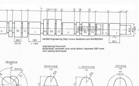
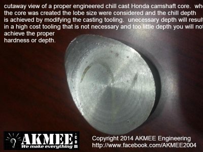
Like I said, if anything I'll do the IM project last so I can see what every one can do. I think we're one of the few with the ability to develop a high quality OEM level core for NSX camshafts so if I do develop NSX products the valve train kit will be priority #1 because there is a need for a reasonably priced valve train kit.


I think we're one of the few with the ability to develop a high quality OEM level core for NSX camshafts so if I do develop NSX products the valve train kit will be priority #1 because there is a need for a reasonably priced valve train kit.
Attachments
Ok sounds like you're out of the game for now then, you mean much later if you're going to develop other projects in the meantime. Glad to hear those are NSX related too though
I don't think there's enough interest for a intake manifold for me at this time. Since there are lot of guys who can fabricate one off IM with al. parts they are better suited for this low volume part. I think lot of people are also observing for now. If a good IM proves to picks up 20-30 bhp (meaning crank) then the lost of engine cover might be less of a concern. Steel tooling to cast a 4 cylinder IM is already at some $50-65k depending on where you have the tooling made. We need to amortize the cost of that into at least 500 manifolds to make it back... so a 6 cylinder IM will be larger in size compare to a 4 cylinder and tooling cost will be even higher.
Camshaft core investment will be a lot less than $50k... so it is way more realistic for me to produce. And based on our experience with Honda B, D, H, and K series engines we can expect a LOT of power from the NSX valve train kit. I can achieve 20-30 whp with the valve train kit + matching header easily, may even more.
Camshaft core investment will be a lot less than $50k... so it is way more realistic for me to produce. And based on our experience with Honda B, D, H, and K series engines we can expect a LOT of power from the NSX valve train kit. I can achieve 20-30 whp with the valve train kit + matching header easily, may even more.
Last edited:
Sounds great, I'll keep my eye out for that too!
Just for reference, here are some pictures of the OEM intake manifold:


You can see how the intake air enters the single entrance opening and then snakes down into the two separate, small, and relatively smooth intake plenums, one for each cylinder bank. When the VVIS "trap doors" below open, the two plenums are connected more directly and their effective volume increases. From the two plenums, the intake air flows straight up into the manifold's 19 cm long, curved runners and turns left or right about 142° before flowing diagonally downwards into the cylinder heads. The oval exit openings of manifold's runners are port matched to the oval intake openings in the cylinder heads. The effective cross section at the mating surface is about 16 cm2 taking into account that the mating surface is horizontal even though the airflow is about 38° from vertical at that point. From there, the air travels about 13.5 cm further through the cylinder heads before reaching the backs intake valves.
If you look at the intake manifold from above, you can see how the pair of runners in the center is pretty much at a right angle to the axis of the manifold while the runners at the ends are not. If Honda had made the plenums longer, all of the intake runners could have come out at a right angle and they could have had larger cross sections. It seems like Honda purposefully wanted to shorten the plenums and reduce their volume.
The overall design looks good for throttle response (minimizing the volume of air between the throttle body and intake valves) and low rpm torque but less so for out and out power. Maybe the Japanese manufacturers' agreement to limit power to 280 PS influenced the design of the NSX's intake manifold.
It will be interesting to see how a naturally aspirated C30A performs with a different intake manifold, not just with a ported and polished OEM manifold.
I should be posting pictures of the finished product(manifold) here in the next week-ish. I need to gauge interest on a group buy to those who (might) be interested so I can give out pricing. I don't expect anyone to commit to anything until results are achieved but just gathering data on interest if the product suits the interested parties I will create a new post when the manifold is officially announced.
-regards
I will create a new post when the manifold is officially announced. -regards
Interested, if you have pricing in mind LMK or PM me
interested also. cant wait to see the final product
Similar threads
- Replies
- 3
- Views
- 194
- Locked
- Replies
- 7
- Views
- 945
- Replies
- 2
- Views
- 1K
- Replies
- 0
- Views
- 2K
- Locked
- Replies
- 1
- Views
- 3K