• Protip: Profile posts are public! Use Conversations to message other members privately. Everyone can see the content of a profile post.

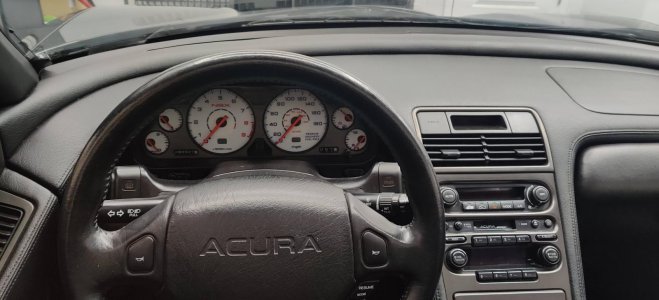
NSX Virtual Display on RealDash app

The low fuel indicator set me back about a week. I did not know there are two resistors in cluster that work with sending unit in tank. When I connected indicator to it, it stay turned on and I know I had half a tank of fuel. I traced the cluster and found those two huge resistors that connect to low fuel indicator are responsible for it. I ordered a dozen of different resistors and found those blue ones are very similar in size and work. I wired two of them and finally my low fuel indicator goes off.

The blue resistors that I got are almost the same and worked!!
7ab5dd95caf20f8e4f1412b45d509cb8.jpg
c460705ad89ed456a41308dc2b3b7944.jpg


Wiring almost done. I added a fuel pressure sensor and stand alone oil pressure sensor.
e65cb98646ccd30501100959300344d0.jpg


Sent from my iPhone using Tapatalk Pro
 
Why not just buy the correct resistors? 300 ohm resistors like the stock ones are not difficult to find. Changing the resistor values by 33% could throw off the reading, depending on how it's wired.

Cool project, interested to see how it turns out.

Yes I would like to get the correct one, but I’m challenged when it comes to resistors. The one I got was the closest that I could find on the web. If you find correct one can you post the link or part number. Thanks


Sent from my iPhone using Tapatalk Pro
 
Resistors are color coded and the easiest way to figure them out is to use an online color code to resistance converter. Gold/brown/black/orange is a 5% tolerance 300 ohm resistor, something like this would be a direct replacement for the factory ones: https://www.digikey.com/product-det...ronics-inc/RSF2JT300R/RSF2JT300RCT-ND/6594507

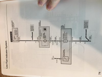
That said, I think getting correct functionality at the new cluster could be a bit more complicated than just buying the identical resistors. This is a diagram from the electrical troubleshooting manual showing how the low fuel light works.

IMG_4001.jpg

Basically, the low fuel indicator sensor (separate from the fuel level sensor) decreases in resistance when fuel is low, allowing more current, which turns the light on. If you have analog inputs into whatever device you're using to read the cluster inputs that might be the best option here, then use a multimeter to pick appropriate resistor values such that the voltage swing in in the range that you need.
 
I've enjoyed this thread a whole bunch, and look forward to more updates!
 
Resistors are color coded and the easiest way to figure them out is to use an online color code to resistance converter. Gold/brown/black/orange is a 5% tolerance 300 ohm resistor, something like this would be a direct replacement for the factory ones: https://www.digikey.com/product-det...ronics-inc/RSF2JT300R/RSF2JT300RCT-ND/6594507

That said, I think getting correct functionality at the new cluster could be a bit more complicated than just buying the identical resistors. This is a diagram from the electrical troubleshooting manual showing how the low fuel light works.

View attachment 164390

Basically, the low fuel indicator sensor (separate from the fuel level sensor) decreases in resistance when fuel is low, allowing more current, which turns the light on. If you have analog inputs into whatever device you're using to read the cluster inputs that might be the best option here, then use a multimeter to pick appropriate resistor values such that the voltage swing in in the range that you need.

Good info, yes I’ll get another one to much it. But take another look at this closeup. I just thought it was red stripe just went dull over 30years but do you think it’s actually orange? I put orange led next to it as color reference.
602dca5dd60383239c89470ba0718043.plist


Thanks!


Sent from my iPhone using Tapatalk Pro
 
Looks more orange to me.

But like I said, based on the circuit shown in the electrical troubleshooting manual, I don't think just matching the resistor values is the right approach to take here. The sensor in the tank is a variable resistance to ground, so you need to be able to convert that variable resistance into a signal that's meaningful to the PDSX-1. What this will entail depends on the electrical characteristics of the thermister in the fuel tank which will probably require some manual testing to get working just right.
 
Last edited:
Looks more orange to me.

But like I said, based on the circuit shown in the electrical troubleshooting manual, I don't think just matching the resistor values is the right approach to take here. The sensor in the tank is a variable resistance to ground, so you need to be able to convert that variable resistance into a signal that's meaningful to the PDSX-1. What this will entail depends on the electrical characteristics of the thermister in the fuel tank which will probably require some manual testing to get working just right.

Sounds good, thanks. I ordered the one with orange stripe and will try to compare when I get it. True test would be to pump out the gas to trigger it to turn on I guess. While I wait on parts I'll work on my other projects :)
 
Are the 300ohm resistors in series our parallel? If series, you can just wire up 3x of your 200ohm, and if parallel, a single 200ohm resistor is pretty close 150ohm for testing. I'm guessing they wanted to divide up the heat dissipation?

Also, the fuel tank sender is quite accessible from the passenger compartment. Take it out to simulate low fuel and put it back in to turn the light off. Apparently, most/all Honda's use the same thermistor so they can be robbed at a boneyard.

Here is a picture of the resistors on the other side. I’ll try to keep it as close to oem with 2 resistors, just have to wait on the new resistors. Those colors got me, lol.

Sweet, so the sending unit is actually accessible from the cabin! This goes on to-do list. Sounds easy to test. Thanks!

e150fd24b16c4a4ceeb1b6cc8a8edf05.plist


Sent from my iPhone using Tapatalk Pro
 
R48 and R49 are in parallel, which means your effective resistance is 150ohm. Any EE on why Honda is doing this? I would presume better heat dissipation, any confirmation?

Your thick reticle is occluding some of the traces though it appears that R2 and R38 (?) are involved somehow too.
 
R48 and R49 are in parallel, which means your effective resistance is 150ohm. Any EE on why Honda is doing this? I would presume better heat dissipation, any confirmation?

Your thick reticle is occluding some of the traces though it appears that R2 and R38 (?) are involved somehow too.

Here is a larger picture. I would assume Honda had a reason to do this but no clue why they would use two instead of one.

0cf7e8409f2a61819c29d8be4f5a0cee.plist


Sent from my iPhone using Tapatalk Pro
 
R48 and R49 are in parallel, which means your effective resistance is 150ohm. Any EE on why Honda is doing this? I would presume better heat dissipation, any confirmation?

Your thick reticle is occluding some of the traces though it appears that R2 and R38 (?) are involved somehow too.

EE here, yeah that's pretty much the only reason you'd use two resistors in parallel instead of one. Two resistors rated for "X" watts each in parallel can dissipate "2*X" watts of power. Maybe it was cheaper than using one bigger resistor, who knows.

R2 and R38 are not involved.

@nsxmugen are you trying to have a lightbulb turn on when fuel is low or are you trying to feed this signal into the PDSX1. If you're just trying to turn on a lightbulb then yeah copy the circuit from the cluster. Wire up the two resistors and the light bulb in parallel, connect one end to +12V, and the other to the wire coming from the fuel tank, just like the diagram I posted before.
 
Last edited:
EE here, yeah that's pretty much the only reason you'd use two resistors in parallel instead of one. Two resistors rated for "X" watts each in parallel can dissipate "2*X" watts of power. Maybe it was cheaper than using one bigger resistor, who knows.

R2 and R38 are not involved.

@nsxmugen are you trying to have a lightbulb turn on when fuel is low or are you trying to feed this signal into the PDSX1. If you're just trying to turn on a lightbulb then yeah copy the circuit from the cluster. Wire up the two resistors and the light bulb in parallel, connect one end to +12V, and the other to the wire coming from the fuel tank, just like the diagram I posted before.

New resistors arrived and they are already replaced. Thanks for helping out with picking correct resistors. I would never guessed it was orange. Yes, I'm only using the LED indicator for the low fuel warning. I'm not using it to be displayed on the tablet, I wanted it to be independent.

Today I drove the car around the neighborhood and it was very cool to watch the rpm's on the screen. Everything work as expected, but it will take time to adjust seeing a display. One observation the low oil pressure indicator is off after the car starts but when I look at it closer it is actually little bit on. The low oil pressure indicator is also wired directly to ECU, makes me think that honda also might had some sort of trickery to totally have it off, maybe also a resistor. But I know I have oil pressure and when it's on you can tell it's light up. When it goes off, its like a light on the lowest dimmed setting. The calculated gear works spot on when aggressively accelerating, but when cruising and taking time to engage the next gear up or down it displays wrong gear until I start accelerating again. I enter all my gear ratios and tire size in to the app.


[MENTION=33247]MotorMouth93[/MENTION] Do you know how RPM and MPH gauges work? I know they don't just have positive/negative wires with signal from ECU. I think there is circuit in the cluster that either converts it to different length or plays with the voltage somehow to get the coils and needle turned. The reason I ask is I notice new pattern with the OEM cluster replaced by this tablet. I have EPS retrofitted from accord but I bet this might be the same case with oem EPS equipped cars. I don't get any steering assistance until 20-30seconds in to a drive. The EPS starts to work after that and it's working fine. I know I have my wires correct for RPM and MPH and error code that I get when I enable SCS is 23 and 27, it's no RPM and no MPH signal.

What I think its happening is that the circuit in the cluster creates some sort of resistance in the wire so the EPS notice it. EPS does some checks and when I drive 20-30seconds the EPS starts to work. It's strange as RPM and MPH are inputs to EPS from ECU.
 
You are doing great, awesome work.

It makes sense that the cluster PCB's process in the incoming VSS (MPH/KPH) and RPM. Amplify it, reduce noise, smooth it and maintain consistent voltage...whatever.

My ETM is showing the VSS goes directly to the EPS.

Does the delay in the EPS have anything to do with the Current Sensor?

Oh, true that it might reduce the noise on the line, but since it's an input from ECU to EPS I did not thought that cluster would be involved in it, but all share same wire so who knows.. I have two tests I want to do, one is easy. I'll simply wake up the electronics before the ignition. So the dashbox that connects to RPM signal will be fully booted-up when I turn ignition on. I'm hoping this would clear the rpm code at list. The second test would be to use my spare cluster that I have from acura CL and just power it up with rpm and mph connected to see if this will clear the EPS light. It's not a big deal to wait for EPS to work 20-30 seconds after driving the car but I know overtime this will eat on me to get the root cause of this.


I'm not sure if this is a delay in the EPS and current sensor. I know all worked fine with oem cluster since. I don't know too much about electronics but it makes me feel that like you said the PCB might amplify/reduce noise on the entire wire RPM wire. The MPH signal must be the same as the codes 23 and 27 are for RPM and MPH.
 
I’m still looking for a solution to my EPS working after starting to drive but I spend some time on new layout in carbon fiber. I try putting rectifier diode but that did not help. I’m thinking I need some sort of one way electronic way not to back feed the rpm signal. If anyone knows let me know. When I disconnect dashbox module eps works from the start, when I have dashbox connected my eps only works after driving. When I connected tech gauge I notice it stops working when dashbox is connected. It must be back feeding or modifying rpm signal at the dashbox module itself. If I have some sort of one way connector I think it should fix it.

I added few gauges to the display. Fuel pressure and oil pressure. Both are stand alone 5v pull-up sensors on the engine.

9a522653140a2c7257a424262f1e09d1.jpg
4b31c0d06b63d16e1df48f9123993040.plist
ce437b123bf198db9c83037ec982e989.jpg
cefd20008f9914ae6aa46dc99943a562.jpg


Sent from my iPhone using Tapatalk Pro
 
I also plan to install the RealDash app in my car since I heard it is quite good and can connect an OBD to get data.

Yea, it’s very well made app, and they are adding features with every new version.

I opt in for yellow needles
744f52a1ffd1f581219644c0df74c61c.plist


Sent from my iPhone using Tapatalk Pro
 
Last edited:
This is awesome, I recently bought my nsx and the rpm needle gets stuck a lot because the previous owner changed the faces to white.

I don't know how to fix this and looking for alternatives such as this

Gotcha, the rpm gauge motor can be replaced from other Honda, like civic or Acura cl etc.. but once you remove it, it needs to be calibrated. I think there is a thread listing diy method to build the calibration module. If it gets stuck look for a pattern, maybe it’s touching something and what ever it’s touching can be grinded off.

There are p&p s2000 retrofit swaps that work great too.

This retrofit build concept that I made works for me, if something brakes I know where to look. I can make adapter plate for it if some one is interested but they are on their own to make it work.

Below is side by side of the old and the new. I’m trying to reassemble my old gauge so I’ll have them it easily changeable.

eb157aac0d9afac6af570174e4b4345e.plist


Sent from my iPhone using Tapatalk Pro
 
Re: gauge stepper motors. There are at least two sizes of motor and the NSX requires the larger rarer one.

Near as I can tell only the symmetrical 4 dial Legend cluster motors can be used. From memory 91-95 or KA5 to KA8.

The RL has lighted stepper motors which are the right size but the spindle seems smaller diameter...so you would have to use it's needle.

I can tell you that the Civic and Accord will not work. Some of the cheap single gauge clusters might be a candidate.

PM me for details.
 
my whole nsx-prime account got wiped for some reason. I'm not only looking for step motor for the rpm but also new faces.
I got some ugly faces.

uz0x2wx.jpg
 
Back
Top