• Protip: Profile posts are public! Use Conversations to message other members privately. Everyone can see the content of a profile post.

Want to add a 12v time off relay to my usb hub for 2013 Nexus 7. How do I wire this?

Joined
10 December 2006
Messages
453
Location
GB
IMG_20160322_071518_hdr.jpg

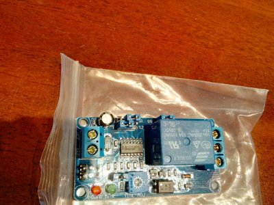
I am wanting to add a small 2-3 second delay to my powered USB hub, so that it turns off after my Nexus 7 is sleeping. I bought this, there are no instructions. How would I wire it up?
I'm guessing VCC + GND is for the 12v that will be going into my USB hub. How do I wire using those 3 output ports on the other end?
 
Want to add a 12v time off relay to my usb hub for 2013 Nexus 7. How do I wir...

Do you have a link to where you bought it? Is it a 12V device? 5V? Does Nexus take 5V? I'm guessing both this and Nexus are 5V.

VCC + GND from the power supply. GND to Nexus. VCC (+5V constant) to center of the three relay terminals. Then one of the sides of the three to Nexus Pwr. The side you use is the one that operates as desired (when one is on the other is off).
 
Last edited:
Do you have a link to where you bought it? Is it a 12V device? 5V? Does Nexus take 5V? I'm guessing both this and Nexus are 5V.

VCC + GND from the power supply. GND to Nexus. VCC (+5V constant) to center of the three relay terminals. Then one of the sides of the three to Nexus Pwr. The side you use is the one that operates as desired (when one is on the other is off).

This is the item:http://www.ebay.com/itm/291704191692?_trksid=p2057872.m2749.l2649&ssPageName=STRK:MEBIDX:IT

My USB hub is taking 12V directly from the under dash accessory port.

***edit*** the nexus is powered completely separately from another 5v source (dcdc USB)
 
Want to add a 12v time off relay to my usb hub for 2013 Nexus 7. How do I wir...

Excellent. So you use the constant 12v (not ignition switched) to supply VCC and the center terminal of the relay. Then the left terminal of the relay, looking from the wire side, goes to power the USB hub. Ground goes to GND and the USB hub.

Hopefully the power drain of this device is not enough to worry about but I would measure it or keep an eye on your battery over times of the car sitting unused.

Edit: looks like 13 mA of standby current drain. That seems higher than I would want. I wonder if you could use a capacitor to hold a relay on briefly as it discharges after losing switched power. That would result in zero steady-state drain on the battery.
 
Last edited:
Excellent. So you use the constant 12v (not ignition switched) to supply VCC and the center terminal of the relay. Then the left terminal of the relay, looking from the wire side, goes to power the USB hub. Ground goes to GND and the USB hub.

Hopefully the power drain of this device is not enough to worry about but I would measure it or keep an eye on your battery over times of the car sitting unused.

Edit: looks like 13 mA of standby current drain. That seems higher than I would want. I wonder if you could use a capacitor to hold a relay on briefly as it discharges after losing switched power. That would result in zero steady-state drain on the battery.

Any changes to be made since my 12v constant is already in use? My USB hub is currrently connected to the 12v switched.
 
Any changes to be made since my 12v constant is already in use? My USB hub is currrently connected to the 12v switched.
To use that circuit board you bought, I think you will need 12V constant. It should be easy to use 12V constant for two things though.

Anyhow, it's difficult (for me) to determine the operation of that circuit board. Maybe the two header pins next to the VCC-GND terminals are the coil of the relay? Maybe the relay operates with VCC-GND? If you apply 12V to the VCC-GND terminal, you should hear the relay click. If you then remove it, does the relay click off immediately or does it stay on for some time? Sorry I'm not being more helpful, but there's not a lot of info on your board.

Also, it looks from other similar boards on eBay that jumper S5 supplies VCC to the center of the relay, so you wouldn't need to connect anything to the center of the relay. But I would test that.

Regarding my suggestion to use a capacitor, I did a quick search and it turns out that the capacitor would need to be enormous, so it's not a good solution. Better is to use a capacitor to hold on a transistor. Look at the response here. (Though you still need constant power for those; it just wouldn't be used once the relay is switched off.)
 
Last edited:
To use that circuit board you bought, I think you will need 12V constant. It should be easy to use 12V constant for two things though.

Anyhow, it's difficult (for me) to determine the operation of that circuit board. Maybe the two header pins next to the VCC-GND terminals are the coil of the relay? Maybe the relay operates with VCC-GND? If you apply 12V to the VCC-GND terminal, you should hear the relay click. If you then remove it, does the relay click off immediately or does it stay on for some time? Sorry I'm not being more helpful, but there's not a lot of info on your board.

Also, it looks from other similar boards on eBay that jumper S5 supplies VCC to the center of the relay, so you wouldn't need to connect anything to the center of the relay. But I would test that.

Regarding my suggestion to use a capacitor, I did a quick search and it turns out that the capacitor would need to be enormous, so it's not a good solution. Better is to use a capacitor to hold on a transistor. Look at the response here. (Though you still need constant power for those; it just wouldn't be used once the relay is switched off.)

Thanks for your help.
Using a multimeter but only understand the very basics, here it is:
When set to check continuity: -Touching GND on 2 post side gets me no beeps on the 3 post side
-Touching VCC on 2 post side gets me a beep noise on the middle post + the post exactly opposite of VCC.
So does that mean the on the 3 post side, the bottom post where I got no sound is a ground. I'll need to have a wire go into that post from the GND on the other side?
 
What that means is that VCC is connected to the center terminal of the relay. When the relay is not activated, it passes that power to one of the other terminals. When the relay is activated, it passes it to the third terminal. That's what is means by NC and NO: normally closed and normally open. The NC terminal is the one you are seeing with continuity to the center terminal when power is not supplied. When the relay switches, the NO terminal will be connected with the center terminal and the NC terminal will switch to being open (disconnected).
 
Back
Top