• Protip: Profile posts are public! Use Conversations to message other members privately. Everyone can see the content of a profile post.

Rising from the ashes - Valhalla

So now on to the new splitter. I used a product called Dibond and also goes by the name of ACM and can be found in sign shops. I got a 4'x8' piece by 1/8 inch and cut it in two lengthwise. I traced some suppport holes and the diffuser openings on both pieces. That way if i destroy this splitter, I have another one ready to go. I drilled out the rivets of the diffusers, supports and mounting plates and reattached them to the new splitter.
 

Attachments

  • Center Supports.jpg
    Center Supports.jpg
    250.7 KB · Views: 72
  • Diffuser.jpg
    Diffuser.jpg
    217.2 KB · Views: 41
  • Rear Supports and Undertray.jpg
    Rear Supports and Undertray.jpg
    271.3 KB · Views: 29
  • Side Supports.jpg
    Side Supports.jpg
    87 KB · Views: 37
Last edited:
And now for the Spliiter Support Rods. I ordered these up from Professional Awesome and they are nice. They also produce the diffusers you see pictured above. The diffusers produce a lot of downforce on their own while also supplying a ton of cooling to the front brakes without me needing to add ductwork. I have an aluminum bumper beam so finding atttachment points for the splitter rods was easy. I through bolted the rod ends into the splitter and bumper beam. then I placed the front lip of the splitter in a postion that was flat with the under tray while still giving me about a 2 degree down plane to increase the effectivness of the overall splitter. Cut the rods to length and then torqued them to 22 ft/lb in the locking clevis end supports. All done. I added some rubber blocks to the bottom front lip corners to prevent too much damage to the splitter itself from my driveway mostly. The beauty of the rods is they do give a little bit when encountering immovable objects. But because they are rods and not cables, will hold the splitter in place and not "flutter" at speed. I'm off to get some E85 and try this new splitter out. Merry Christmas to you all.
 

Attachments

  • Splitter and Rod Supports Detail.jpg
    Splitter and Rod Supports Detail.jpg
    270.7 KB · Views: 34
  • Splitter and Rods Supports Installed.jpg
    Splitter and Rods Supports Installed.jpg
    312 KB · Views: 34
  • Splitter Finished.jpg
    Splitter Finished.jpg
    267 KB · Views: 35
  • Splitter Rod Supports.jpg
    Splitter Rod Supports.jpg
    111 KB · Views: 42
Last edited:
So what have I been up to lately? Mostly driving and maintenance. Replaced front tie rod boots, interior bolsters and interior sash triangles, tuning the sound system and insulating the ATW coolant lines and resevoir in the front compartment. just little things that don't require pictures.

But one thing I did do, was to play with the controllers for the turbos. I am still happily running the Aerochagers 66 Series large frame turbos. They have a wastegate that moves a rod that adjusts the variable vanes to adust exhaust gases to the compressor wheel for maximum force, boost and response. By turning the controller in, you would slow the response. The general rule of thumb was to screw the controller adjust in 1 to 2 turns. The popular opinion was that you didn't want to go less than one turn in for fear of the vanes causing a choke point up at the top end. So I had mine set at 1 and 1/2 turns in. I did get into boost but it started coming on around 45oo rpms and slowly ramped up. The turbos worked but I didn't really feel the boost until vtech. For reference these are the same turbo that they upgraded the Porsche 930's, the nicknamed "Widowmaker". Hench the nickname for my car.

So one day while under the car doing inspections and maintenance, I got to thinking. Regardless of where the controller position starts, it can't produce a choke point up top because the vanes are completely closed, regardless. At full boost the controller spring is fully compressed, forcing the control rod to fully close the vanes. And the only reason to screw in the controller was to close the vanes at no/low boost. So what if I unscrewed the controllers all the way out so the vanes were wide open? In theory this would cause the compressor wheel to come up even quicker with more boost sooner. So that's what i did.

The result was a huge jump in power and torque mid range and no lag! I haven't had the chance to pop her back on the dyno but my butt tells me I've picked up over 75 ft lbs of torque by 35oo rpms. The power gains in the mid range feel incredible and with no loss on the top end. The car feels much different and I'm way happier to be on power before vtec rolls in. It really is a new car.

So what is next? I'm looking into the S2k steering rack. That should be fun!
 
NSXMugen sent me a note to inform me I had a lot of broken links to pictures so I got that fixed. All documentation is now back where it belongs. Been spending a bit of time in the front bay. Cleaning that part up and moving parts around for the next chapter in this build. An S2k steering rack comversion. So I got dimension from NSXMugen for the EPS Control box and made room for it's install. Hope to have the controller and wiring harness next week while I wait on the rack itself. The box I used as a mockup is a little bigger than the real thing but I wanted to make sure I had enough room to place it. I think I will go with the horizontal position. Orientation of the box does not alter it's function.

David used the TPS warning light in the gauge cluster as his EPS warning "idiot" light. But it looks like even 1991 NSX's have the EPS warning light in the top right position, next to the TPS light. Even though they did not come with EPS. So next week when I get to wire this up I'm going to see if I have a diode in the EPS location in the gauge cluster and if so, will use the native location EPS light for monitoring.

Also after some digging I find that the front fuse box has a location for an EPS fuse link on the main bar between the Wiper fuse and the Blower fuse. Depending on how involved getting wire to the fuse box I may use that location for a totally stealth look. We'll see.
 

Attachments

  • Inked Front Fuse Block.jpg
    Inked Front Fuse Block.jpg
    109.4 KB · Views: 42
  • Control Box mount horizontal.jpg
    Control Box mount horizontal.jpg
    147.5 KB · Views: 39
  • Control box mount vertical.jpg
    Control box mount vertical.jpg
    154.1 KB · Views: 38
  • Driver Side Frame Rail.jpg
    Driver Side Frame Rail.jpg
    454.8 KB · Views: 33
  • Driver side Frame Rail 2.jpg
    Driver side Frame Rail 2.jpg
    155.2 KB · Views: 33
  • Front Bay with Duct.jpg
    Front Bay with Duct.jpg
    477.7 KB · Views: 33
I received the EPS Controller from David yesterday but no harness. The box with bracket weighs about 5 pounds. Might as well wait for everything to arrive so I only have ro rip apart the front of the car once. Also have some hose heat sheild coming from Funk Motorsports UK to insulate the Intercooler hoses in the front bay from radiator heat.
 

Attachments

  • EPS Controller and Instructions.jpg
    EPS Controller and Instructions.jpg
    108.2 KB · Views: 32
So I spent a lot of time today ripping apart the front end of the car. I had to relocate the twin Hella horns out of the front bay and onto the bumper beam to clear the way for the new radiator ducting that I will create. I'm going with a new radiator shroud with twin Spal 11" fans which will move a lot more cfm's that the OEM single fan. After that is installed I'll create a duct from the radiator to the shallow vent of a Seibon/VIS hood. Need to grab some large pieces of cardboard so I can mock it up.

Removed the undertray, splitter, battery and battery tray so I could get access to mount the EPS Control box. Aluminum rivnuts to the rescue and the box is secure. Now to clean up the battery tray and relocate the WTA intercooler pump beside the battery (rivnuts) and then clean and polish the tray. Will repaint the undertray and touch up the splitter.

Had the front tires rebalanced too as I was getting a little shimmy at freeway speeds. It disappeared above 9o but don't need to replace the front tires yet, just the rears! Will do some more maintenance while the car is in the air like cleaning up some wiring rat nests, look over the turbos and add some oil, and clean and polish various parts. As the front bumpers are off, I just may rewrap them too. If so I'll try my hand at PPF as well. Now that anyone can obtain the good stuff.

And why am I tackling all of this? My wife has surgery Tuesday and will be laid up for a while. I need to keep myself busy.
 

Attachments

  • EPS Control Box Installed.jpg
    EPS Control Box Installed.jpg
    135.6 KB · Views: 35
Working on things as I wait on parts. I have new titanium rear end link bolts coming from Track Addict. Waiting on the Spal fans and shroud from Coz. Waiting on the EPS rack, crossmember, and harness from NSXMugen. So I have been cleaning, prepping and painting. But one thing on my list was to rewrap the front of the car and then apply PPF to keep it pristine for a while longer. I had wrap left over from the last wrap and hoped I had enough. But I ran short by two feet! So I'll wait on another roll to arrive from CheetahWrap so I can finish the front bumpers. But I am mildly impressed with my efforts on the hood, fenders and headlight covers. It's coming along.....

Also looking for four (4) double barrel crimp male pins like in the picture below. The spade measures 6.3 x 11 mm. This is for the connector between the radiator fan and the wire harness to the ECU. Anyone have some laying around?
 

Attachments

  • Front End Re-wrap 5-25-23.jpg
    Front End Re-wrap 5-25-23.jpg
    329.4 KB · Views: 30
  • Radiator fan double barrel male connector.jpg
    Radiator fan double barrel male connector.jpg
    131.4 KB · Views: 27
Last edited:
A minor update for today. picked up the shroud and fans from @Coz on Sunday. Wired in the OEM female connector from the OEM fan and mounted it in place. I had to remove quite a bit of relays and other bits from both sides of the bay near the radiator to slip it in. And because it's so large I had to remove the top hose and drain some coolant. Yippee, I get to bleed the coolant system. Again. I also need to shorten the top hose at the bottom where it seats to the hard aluminum pipe as I have zero clearance between the hose and the fan. Yeah, coolant everywhere, what fun!

An update on the fans should you want to add more cooling power. These and Spal 11" curved blades (quieter) and push 1328 cfm's each. I was very concerned with the amperage load and the great news is these each only pull 13 amps so I am +10% below the 30 amp circuit maximum. I left the resistor intact for low and high speed action. At this point there is not much left to do. I'm going to hold off on building a chimney to the hood vent until I'm absolutely positive I need it. I've got enough other projects on hand for now.

Addition - I just received the rear toe link adjustment bolts that @TrackAddict did a group buy run on FaceBook. These are titanium and as Acura has none of these available, and does not plan on producing any more, this is the only option. I'll get them on tomorrow.
 

Attachments

  • shroud and fans driver side.jpg
    shroud and fans driver side.jpg
    130.1 KB · Views: 20
  • Shroud and fan passenger side.jpg
    Shroud and fan passenger side.jpg
    132.2 KB · Views: 20
  • Tie Rod Adjusting Bolts.jpg
    Tie Rod Adjusting Bolts.jpg
    103.5 KB · Views: 26
Last edited:
Somethings are getting shipped to me tomorrow! I'll spend the weekend removing the existing rack and pinion rack and pulling apart the dash in anticipation of hopefully getting back on the road next weekend. Yes, I'll take pictures along the way.
 

Attachments

  • Chassis Brace & Brackets.jpeg
    Chassis Brace & Brackets.jpeg
    271.2 KB · Views: 23
  • Chassis Brace.jpeg
    Chassis Brace.jpeg
    318.7 KB · Views: 25
Last edited:
Somethings are getting shipped to me tomorrow! I'll spend the weekend removing the existing rack and pinion rack and pulling apart the dash in anticipation of hopefully getting back on the road next weekend. Yes, I'll take pictures along the way.
I forgot to mention to you earlier!!! I hope David revised his mounting brackets per my feedback. The rubber strips/pads that he used was inadequate to hold the rack in place. I suggested to him to hard mount the rack to the brackets. I've done that and it's been excellent.
 
I forgot to mention to you earlier!!! I hope David revised his mounting brackets per my feedback. The rubber strips/pads that he used was inadequate to hold the rack in place. I suggested to him to hard mount the rack to the brackets. I've done that and it's been excellent.
I'll let you know when everything arrives but his instructions now include a passage where the steering rack bolts directly to the battery tray for even more support.
 
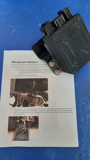
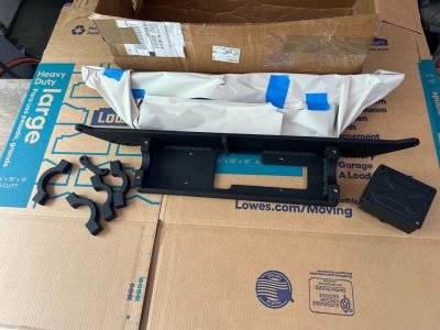
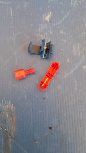
So I have been pretty productive over the past three (3) days. I received a very heavy package from FedEx on Saturday afternoon. It was the EPS, chassis support and other bits. I had everything ready to put it but was concerned that there wasn't enough adjustment in the Outer Toe Links to get a proper alignment. I fiddled and adjusted and measured and remeasured. I just didn't see how this was going to work so I set up the wiring and connectors and just parked it.

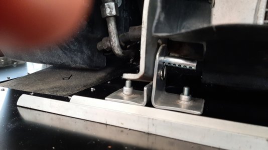
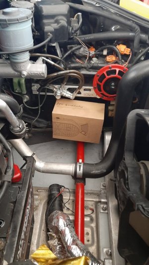
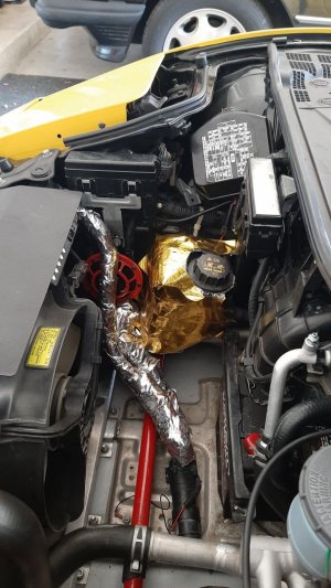
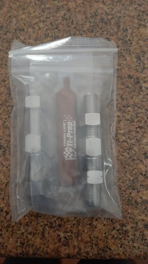
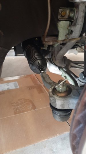
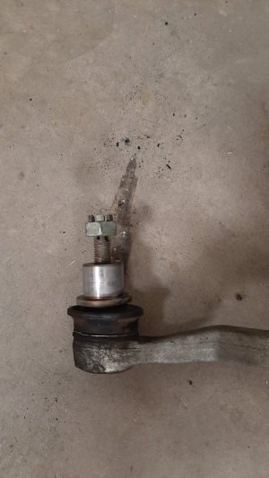
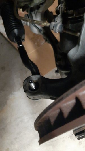
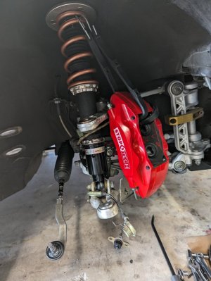
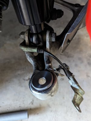
About 2AM on Sunday I woke up thinking of how to fix this. I tossed and turned and finally got up at 4AM to start on this project again. I will not be defeated! So I loaded the rack and crossmember on my jack, hoisted it up so I could connect the end links and wrestled the crossmember into place. It bolted into place with very little effort but now I had another dilemma. The end link bearings were still on the OEM rack! After contacting David (NSXMugen) he informed me that the inner tie rods had been created to accept the OEM outer toe links. I was saved! I installed the OEM outers back on the rack and mounted them up. Perfect.

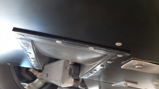
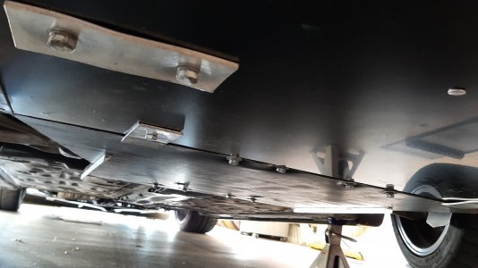
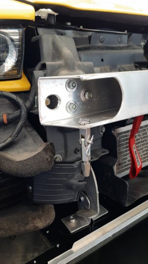
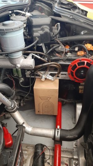
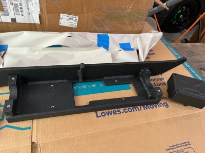
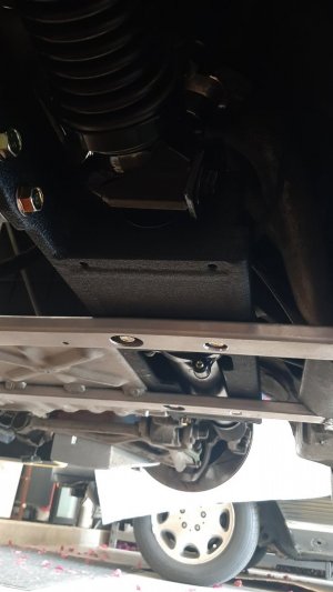
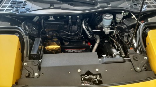
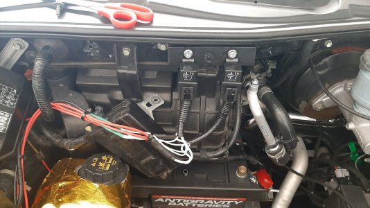
I still needed to amend the battery tray with some additional support bolt holes to attach the tray to the EPS crossmember. Bolts were suppled and the EPS unit is fully mounted and strong. It's not going anywhere.

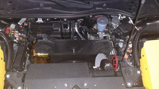
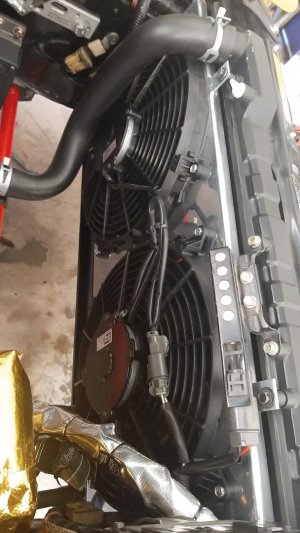
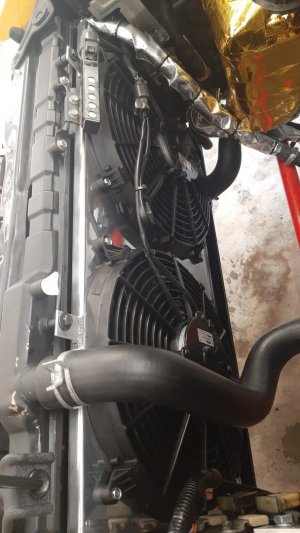
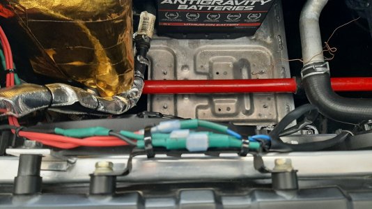
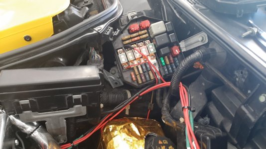
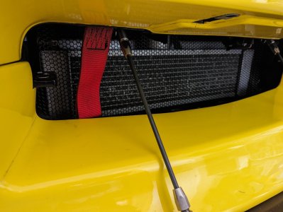
So today was putting the battery back in the car, finish wiring the four (4) sensor wires for RPM, MPH, Ignition and idiot light and seeing all of my progress. Little did I realize that today, my wife's birthday, I was doomed to fail. First of all the car started right up and I watched the coolant temperature level rise knowing I was going to have to bleed coolant. Again. What I wasn't prepared for was the newly installed Spal fans not operating! Nothing. I shut it down once it reach 200F. WTF? I started digging at connectors and tracing wire and just going nuts. Quick call to 
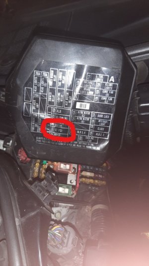
@Coz and we talked thru some scenarios. And then he hit me with the proper order of tracing electronic issues "Did you check the fuse?" Why no, why would I need to do that, it worked fine before. So after replacing the blown 30AMP fuse, the fans fired right up. So did I now start to feel lucky? Read on.

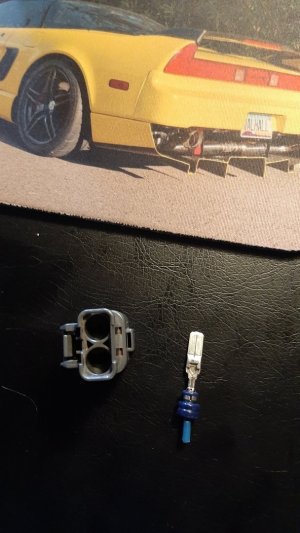
When I did fire up the car I did notice, several times that I did not get the EPS warning light to illuminate when turning the key. It was supposed to flash twice then go out to let me know it was working. It wasn't. So I double checked all the connectors to make sure they were locked. They were. I double checked all of the sensor connections and they were solid too. I removed the gauges again to make sure I had live bulbs in the EPS location and just to make sure, and double checked to see if there was a bulb in the TCS location. Installed the gauge and connectors and fired the car up and no light and no EPS. I changed the idiot light location to the TCS light, still nothing.

So I'll wait to talk with David so I can progress to finish this project. I'm so close.....

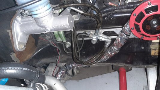
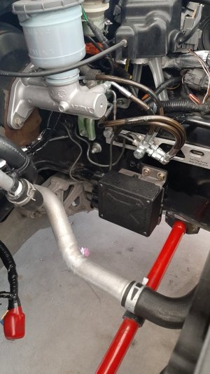
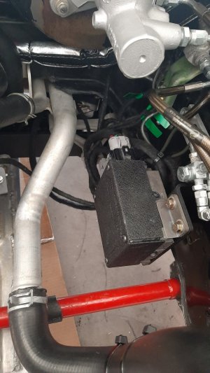
Update: So I put the multimeter on several harnesses and the control box too. Power going into the box is confirmed and the ignition lead is hot as well. But no power coming out of the box to the rack itself. Looks like I have a dead control box. David is shpping me another box and should have it Thursday.
 

Attachments

  • Right Tie Rod Mounted.jpg
    Right Tie Rod Mounted.jpg
    82.1 KB · Views: 19
  • Old Tie Rod with Bushing.jpg
    Old Tie Rod with Bushing.jpg
    109.7 KB · Views: 17
  • New Tie Rod End Minus bushing and Tophat.jpg
    New Tie Rod End Minus bushing and Tophat.jpg
    73.6 KB · Views: 17
  • EPS Rack Mounted.jpg
    EPS Rack Mounted.jpg
    83 KB · Views: 17
  • EPS Control Box and Connections.jpg
    EPS Control Box and Connections.jpg
    126.1 KB · Views: 20
Last edited:
so coz is still around....tell him I said Hi.
 
Maiden Voyage

So I put her down on the ground last night, after refabricating some supports for the undertray and mounted it. I had to step back and admire her again, all over. It's like that post of @Honcho when he stood beside his beauty after the PPF had been applied. Just grinning ear to ear.

This morning I adjust the ride height to NSX-R specs, only had to adjust one coil over by only two turns. She is square. She fired right up. Let her warm a little, the TCS light remained on which is my trigger idiot light for the EPS. I tried to wire the EPS idiot light but the circuit must not be complete in pre-97 manual cars. So I used the TCS light. It remained on the entire drive. But I had EPS and WOW what a different car! Steering was quick, accurate and instant. It's like driving a new car. Alignment appointment is set for a couple of hours from now. I can't wait to see how she handles after that. But this initial drive was not with out hiccups.

The steering wheel was off center which was to be expected. So I got that back to center the best I could before alignment. And surprise, surprise, my radiator fans did not come on. Blew another fuse. Got her home, placed another 30amp fuse in and it blew immediately. The reasoning behind this is they only draw 26amps while running but when powering up can draw close to 40 amps combined. So I'll visit @Coz tomorrow and we'll wire in two (2) 40amp relays, one for each fan, on their own individual 30amp fuse. I will not be having any more issues there. And the EPS control is throwing codes but still operable. So I have some more questions for @NSXMugne. The codes were 21, 23 and 14. David just got back to me and his thinking is these are just stored codes when he was bench testing the system and they are ground fault codes. He claims they will go away over the next few drives. But my goodness does it feel good and I can't wait to hit some twisties. Pics to follow.
 
More Progress

So I got the car aligned and it does feel way different. Added a little toe in for the front end based upon recommendations of those who have done the mod, inclusive of @RYU . Added some more rear camber as well. What a ride. I sure didn't realize how much the front springs were compressed. It drives way nicer and turning the car is so easy now. Still have some issues with faults and it not being perfect but will try to rectify that over the holiday.

But I did get over to @Coz and we wired in the fuse and relays. Fairly straightforward. We put male and female connectors on the fans in case I ever had to replace one. That way I wouldn't have to cut into a harness. Just finished tidying things up. Now waiting on new connectors for the steering portion. Happy 4th to all.

Oh, and @docjohn, Coz says hi right back at you.
 

Attachments

  • Finished.jpg
    Finished.jpg
    357.5 KB · Views: 20
  • Fan Male & Female Connectors.jpg
    Fan Male & Female Connectors.jpg
    337 KB · Views: 20
  • Fuse Box and wiring.jpg
    Fuse Box and wiring.jpg
    334.4 KB · Views: 20
  • Relays and Wiring.jpg
    Relays and Wiring.jpg
    384.2 KB · Views: 19
EPS is Fully Functionable

Got the T-Taps and ripped into the wiring again. I had previously done 14-18 gauge taps for the trigger wires to the tiny gauge wires in the OEM connectors. I had feared that bad/no connections might be my issue and I was correct. I tore the blue ones out and replaced the with 18-24 gauge T-Taps and that was the trick. Fault codes disappeared and the EPS fired right up with the car. Will need to drive some miles to clear the old codes and then I can calibrate the steering. But what a relief. The car is awesome again.
 

Attachments

  • T-Taps.jpg
    T-Taps.jpg
    67.6 KB · Views: 28
I had to realign the car after replacing the original S2k rack and control box. Everything works perfectly. I eyeballed the alignement in my garage so I could get the car to the shop. I guess I must be slipping some as I was off a bit. 1mm! That was all. Ravi shot a you tube of the car as I pulled out.

 
So what have been the latest projects? Stand by.

I had notice a loss of power, not a lot or suddenly. Just gradually. I feared it might be the controller on the passenger side turbo and sure enough. It was froze solid. So I pulled it off and sent it to the Turbo Doc in Utah for repair. He is the only person left in the world who can work on Aerochargers and he has parts too. Should get it back next week. Also reasonably affordable on the bill. About half the cost of repairs that Aerocharger would have hit me with.

So the old "while you are in there". Relocated some wiring under the hood for the new Spal fans setup, just to clean stuff up. Removed the undertray with the thinking that with that in place I might be impeding air flow out of the radiator. We'll see if there is any improvement. I also ordered some grill material from CarGrills.com and spent half a day creating and installing grills for the AC condenser openings and the radiator. Since I run a MASIV radiator and plan some track days and a long trip to Texas for NSXPO, I don't want to be sidelined by a road debris damaged radiator in Roswell, New Mexico! I'll post up some pictures soon,

I also raised the car a little to aid in handling and saving my splitters. Took a couple of times as I raised it too far and it looked like a 4x4! In the end I'm about 1/4" above Type-R specs but also running 17/18 wheels. Also adjusted caster and it was set way too aggressive and I wanted to get it back to stock setting or +8 degrees. Should be lighter in steering effort too.

I installed, a while ago, a new 5-pin relay to fully replace the OEM main relays. I spotted it on FB and it came with a kill switch. I purchased an additional relay for $15 at the local parts store to keep in the glove box. Just in case. But I doubt I'll ever have to need it. Modern relays for the win. I initially just installed the relay but the thought of adding the kill switch as an additional anti-theft got the better of me. And as I was going down my list of repairs i came to the key replacement. I've only had one key for the past 5 years. I made mention to my better half that I would need to go the dealership to get a new one made and then she said "wait a minute". Two minutes later she comes back with the remote for door locks, a main key and the valet key! She had been holding on to them the whole time! I feel so much better now.

So by next weekend I should be fully functionable and looking forward to some nice driving. Can't wait, the weather should be turning nice very soon.
 
Quick update. As i had moved the car up vertically a 1/4" (or so I thought) I decided to double check the camber on all four wheels. it had changed quite a bit so I lowered it back to Type-R specs. Now the fronts are even and at -3.2 and the rears are even too at -2.1. I plan to get the Driving Ambition (CompTech) off center camber adjustment bearings so that I can adjust more if I need, but these are just about perfect numbers. But the ability to adjust up or down from these numbers would be optimal.

I also moved the end links on the Dali Trophy 1 1/4" front sway bar to the last (softest) setting as the car was too flat cornering and not really transferring any weight to the outside tire. Track days are coming up next month and I want to be ready. So then off for a quick drive to check out may handiwork. I like it. I like it a lot. Everything works. Now how often can you say that about a car that is over 30 years old!
 
So what now you ask? Well after my initial drive I parked the car in the garage. The next day I go out and see the car has 'settled". And my perfect camber numbers were anything but. The rears looked like a stance/drift car with camber over - 3.2! So I jacked up the back of the car and was able to reduce that down to - 2.1. OK so we are good here.

On to the fronts. What I thought were perfect were now down to - 2.0 on both sides. Oh crap. There was no more adjustment left on the camber bolts so the only thing left to do was to install the CompTech Camber adjustment bushings. Just great, I really love fooling around with ball joints. I had ordered a full set of upper and lower bushings and decided to add one to each side and see where it got me. So take everything apart and apply my ball joint separator. Sure enough, the very first ball joint threads got mucked up. Just great. Pull the knuckle completely off to see if there is any hope for saving the ball joint. The simple answer is "NO". I proceed to pull apart the other side with a bit less drama.

Removal of the OEM bushings is straightforward with a C-Press. For install, I put the CompTech bushings in the freezer over night and they pressed in nicely with very little issues. The "While you are in there" syndrome kicked in and I thought it a perfect time to replace the original wheel lugs with AEM extended lugs. I did both front axels and reassembled the driver side. Went together well. As to the passenger side.......

I have a new ball joint coming from Rare Parts. But now find that no one wants to touch removing the existing ball joint and pressing in a new one. By incorrectly pressing (in or out) you could fracture the knuckle and it would be useless. I'm now waiting on ATR to see what they have in stock. Anyway some random pictures of grills and suspension porn.
 

Attachments

  • Rdiator Grill.jpg
    Rdiator Grill.jpg
    188.8 KB · Views: 12
  • Front Right Suspension.jpg
    Front Right Suspension.jpg
    140.4 KB · Views: 12
  • Comptech Lower Offest Bushings.jpg
    Comptech Lower Offest Bushings.jpg
    103.7 KB · Views: 12
  • Front Right Knuckle.jpg
    Front Right Knuckle.jpg
    110.1 KB · Views: 12
  • Front Left with Extended Studs.jpg
    Front Left with Extended Studs.jpg
    111.2 KB · Views: 12
Last edited:
Back
Top