• Protip: Profile posts are public! Use Conversations to message other members privately. Everyone can see the content of a profile post.

bogle's 1991 mild build thread

As another data point for you, my idle oil pressure settles down to 31-32 PSI at the same RPM level as RYU. This is after about 10 minutes of warm up time. PSI goes to as much as 110 when briskly accelerating. Using the SoS oil pressure sensor as well.

Also, our cars look very similar (except mine is in red)! Love it.
 
[MENTION=36953]bogle[/MENTION], if you're constantly fighting noise on your input pins, does it make sense at some point to go to something like an Infinity or Haltech? It would drive me nuts to spend so much time fabbing up the amazing stuff you've done only to have it not work right because of an essentially un-fixable hardware issue.

Yeah a haltech is the long term plan. The problem is it’s a huge project. The car runs really well now, and I’d be starting from scratch. I’d have to take it to the dyno and do all the partial throttle stuff again. I did look into making a base map, and even that was pretty involved. I have to do some research on a number of engine params to even get it to fire. I reached out to a couple people with known nsx haltech setups and they wouldn’t share a basemap.

My plan is to stick with the current ecu until I get some other big stuff done: AC, coolant hoses, maybe abs, then tackle it. That stuff is more pressing.

In the interim, I’ve been meaning to open the ecu up. There should be 6 extra adc inputs available, on top of my 2 noisy ones, but that aren’t exposed at the plugs. I’m sure they used the same boards for all the ecus, just different plug configs. So I wonder if I can somehow tap into them. Maybe a header laying around? I dunno yet.

Even if I can’t get better inputs, it’s ok for now. It’s still useful to know that I have oil pressure and to see trends and to have all the sensors I want wired up so they all work with the eventual haltech
 
As another data point for you, my idle oil pressure settles down to 31-32 PSI at the same RPM level as RYU. This is after about 10 minutes of warm up time. PSI goes to as much as 110 when briskly accelerating. Using the SoS oil pressure sensor as well.

Also, our cars look very similar (except mine is in red)! Love it.

Great, thanks! So that data is from the SoS sensor? Or an aftermarket sensor/gauge at the SoS sensor location?

Edit: I just looked at your stroker thread, so cool!
 
Last edited:
When I took apart my AEMv1 I found that it has 2 boards, the application specific board that has the Honda connectors on it and the actual AEM engine computer board, and there's a 100 pin connector between them. Tapping into any unused inputs should be pretty simple. I wonder how much of the signal noise is due to the application specific board and how much of it is in the generic board.

IMG_1798.jpg


IMG_1799.jpg


IMG_1800.jpg


IMG_1801.jpg


IMG_1802.jpg


Using the OEM oil pressure sensor location and an AEM sensor and gauge, my car idles around 20psi when completely warmed up with 10w30. 30 is pretty high for a stock car at stock idle speed - a lot higher than can be accounted for by worn clearances - Ponyboy what oil pump and oil weight are you using?
 
Great, thanks! So that data is from the SoS sensor? Or an aftermarket sensor/gauge at the SoS sensor location?

Edit: I just looked at your stroker thread, so cool!

Data is from the SoS sensor. FWIW, the sensor does seem more "consistent" and quicker to respond. Not sure if that's characteristic of the SoS sensor or an indication of my OE having degraded performance.

Thanks for the compliment. :)
 
Dash oil pressure gauge numbers aren't reliable as far as getting real numbers goes, even with an SoS sender. My dash gauge says 2 bar/30psi at idle, real gauge says 20.

On my car, the oil pressure PSI and temp and water temp and speed in mph are displayed through a Defi OLED screen.
 
[MENTION=4055]Ponyboy[/MENTION], just so I understand your setup, you have the SoS sensor feeding into a defi control box as well as the stock dash gauge? Did you have to convert it to 0-5v, or does the defi box take a simple temp thermistor input?
 
[MENTION=36953]bogle[/MENTION] - I believe you asked about my sensor location. I run off an SOS oil filter sandwich plate. IIRC I went with theirs because they had a one size bigger AN Fitting than the rest. However, i'm not running my sensor through there. I'm running both my oill pressure and oil temp sensor from the bungs on the oil cooler. IIRC my pressure line is after the cooler and the temp is pre-cooler. This gives me kind of a worse case scenario in terms of readings or so I thought... I believe due to the 2-3ft lines it will account for some pressure drop as opposed to taking readings from the sandwich plate or directly from the heads.
 
I got a couple more wiring projects done over the weekend: an integrated charging cable, and I removed the head unit. If you would have told me a year ago that I would spend 50% of my time on this thing doing wiring projects, I wouldn't have believed you. Someone else's modified car, I guess.

Headunit

Since the navpod install, the headunit in there has been redundant. The plan was always to run music from the navpod, then get rid of the headunit. And it would be a good opportunity to clean up some wiring. Not sure if anyone remembers this:

3e5851ce1221c84ff2702c435cf103c4.jpg


A lot of that is unnecessary, and the plan was to clean it up.

What should I run in the head unit's place? Good question. The best thing I found for now was a couple single din pockets. I really want some amount of storage in the car. With the headunit and aftermarket center console, there was no place to put my phone. It'd just slip n slide around the car. I got a vent phone mount, but it interferes with everything and blocks some of the navpod. So these pockets. Here they are in the head unit's frame:

10b9fa0d64284090d580ee05cf8ec8c1.jpg


I'm getting pretty good at taking apart the console. I can now take the entire thing apart in like 10 min.

This time, I spent a lot of time tracing wires and trying to understand the stereo wiring, plus generally looking for stuff I could remove. I also had to remove the glove box, so I spent a little time digging around the alarm wiring.

I still dont undersand everything, of course. The center speaker isn't hooked up, and I mean WTF is this? It was just hanging out below the headunit. Okay.

385d8297c55d343c39e2f99aca1ba994.jpg


Making progress:

d6dd62d9bc0675157d299652282dbc50.jpg


The wiring finished for now. Is it perfect? No. Is it better? Most definitely. Suck less every day, you know? It will probably change in 2 months anyway. There are still some bundles of wires in there, but they are more tidied up, untangled, and shoved below the headunit area. Making the wiring nice could be a several week job on it's own! Maybe someday when all the accessories are in their final form...

0350f04eebd5af03de9317be41020efa.jpg


Next step was to put the console back together. How do those single din pockets fit? Like hot garbage. They are wider than the hole, shorter than the hole, and the hole is off center. Not ideal, but it's fine for now. It may look like your teenage cousin's souped up 91 toyota tercel, but it is so much more practical than the previous setup. The USB input is right there, and the phone fits without interfering with the CCU or gauges.

10f7b45362e072b733f1766867d17df2.jpg


I'm not totally sure what to do with the center console long term. Eventually there will be no gauges, then I can do something nice. The aftermarket console has never really fit, so it'd be great to get a new one. I know there are some vendors that make super nice carbon units. I really want the stock pocket flap and the coin tray area. But then in the headunit area, what goes there? I'm not sure yet. I'd like to have storage if it looks clean. Or maybe an integrated phone mount (magnetic?). I dunno. Let me know if you got ideas!

With these kinds of projects, the things I think will be issues never are, but there's always some other weird bug. The headunit has a bit of static when not playing music. I tried some different grounds, but nothing had an effect. I'll track that down later, though. Also, the headunit wants to always run the antenna up, no matter what's playing. So no more power for you, antenna. It's fine, if I listen to music, it's only outrun anyway. Gotta keep up that 80s/90s vibe.

No more!

fc6eb2b3ea082a1e88ff2b8c149fbd64.jpg


Charging cable

Since I've had the Shorai battery, I've needed to pop the hood to plug the charging cable in. Because the battery is made for bikes, they dont make a long cable. So the plan was to make one.

I bought an extra charging cable, and cut it up to see how it was made. It's a 7 wire cable, 2 power wires at 20awg, then 5 other 22awg wires (probably metric tbh, but close enough to 20/22awg).

fafe92569ee9fa892d81bb5a4f75a70a.jpg


I managed to find an 8 wire cable with the same setup (2 power wires at 20 awg + 6 22awg wires) on amazon to use as an extension. The ultimate cable ended up being 64" long. I have 20 more feet of this 8 wire stuff. If anyone needs some, lemmie know. Soldered together:

dc9a06dc01a8fc22751534681d2aa633.jpg


I threaded it through some stuff, and it fits pretty well:

26b4227cd6022263351e7d3e485271ac.jpg


The plug at the bumper was the most difficult part. I wanted it to be hidden and out of the elements, but also easily accessible. Originally, I wanted it near the tow hook, behind the cover, but nothing really made sense. There is a little pocket behind the top part of the bumper, though, which ended up working the best. There was even a built-in little tab behind the bumper I could ziptie the charging cable to. It seems pretty snug when up in the pocket, and it's easily reachable when I want to charge it. We'll see how it woks over time.

8d6e6fd09a8f6e1c675e686e054d0a08.jpg


Current draw

About a month ago, I went to take the car out and .... the battery was dead. It had been sitting for 2 weeks off the charger. This is the longest it's been off the charger since I've owned it. Small battery lyfe, maybe? I've left it a week without the charger before and it's been fine. I guess I spaced plugging it in. This was post-navpod, so I thought maybe with both stereos the current draw was higher than it should be. Or maybe the new navpod is a power hog.

So I charged it up, went to unlock it with the fob, and it chirped. It had never chirped before. A bit unsettling. Well, we still had to get lunch, so we took it out, parked, got some sandwiches, and ate them about 20 feet from the car. Occasionally the car would beeeep. Again, new noise, dafuq is going on.

The whole thing stressed me out a bit, so during this head unit process I spent some time trying to understand the current draw and the alarm system.

I wanted to get before headunit removal and after current draw metrics. But in the before check, I didn't understand how the system behaved, so I got bad readings. I'd plug the meter in, which effectively hooked the battery up, and it'd draw like 0.5A (!!). Then fluctuate between .5A and .8A. I'd leave it on for 10 or 15 seconds, then pull the wire cause it seemed really high. I did that a couple times, thinking holy crap, no wonder it died.

When I had both stereos unhooked, I took another reading. After a few seconds, it read ~32mA. Ok cool. Reasonable, I guess?

I got the new navpod stereo hooked up, and took another reading. It did the same 500mA thing, fluctuated, then about 30 seconds in, it dropped to ~45mA and stabilized. I guess it's doing some setup stuff? Not sure. I want to do some more current draw testing, like when the alarm is on. If anyone has data on their car, I'd love to hear it!

On the alarm front, I think it has been in valet mode the entire time I've owned the car. Turns out there is a proximity sensor, and it's pretty sensitive. The day I took the car out it was really windy, probably triggering the proximity sensor, and sending warning beeps. Maybe the battery dying reset the alarm system? It's weird because the battery has been disconnected many times, but maybe never for that long.
 
Last edited:
kanye said:
I went to Jacob an hour after I got my advance, I just wanted to shine

Except I have not yet received an advance for my upcoming rap album, and in this case Jacob is a much less illustrious Japanese parts website.

7522b91e74db0f44b50292d09564dfc3.jpg


2aef87a0e21723ee5cc50334f74dd14e.jpg


I've wanted this thing for a while. My stock bar was dull and the mounts were a little rusty. Now I’m wishing I added new top hat nuts to my recent amayama order, but it’s fine. It looks good! Gotta have the JDM bling

32839092bf95aa62c0c6b44379eb77df.jpg


c55a9ea01ccae1df56f25d132e2a343d.jpg


714b44b6323de362172a2f33e486122e.jpg
 
I managed to make progress on a couple annoying behaviors in the tune. These are really the last bugs in it preventing stock-like behavior / drivability:

* Idle catch: when I'd let the revs drop to to idle, it'd drop way below idle and feel like it was going to die.
* Hot start: There was a lean condition when it would start at temp
* Hot start: It'd require tons of cranking when starting the car at temp

This stuff has been a minor pain since I've owned the car, so nice to make a little progress on it.


Idle catch

When I got the car, it would die on occasion when I'd let the revs drop, like when pushing in the clutch coming to a stop. I made some changes a while back that made it not die, but it would still drop way down (500ish) and feel like it was going to die. I developed a habit of heel-toe blipping the throttle when coming to a stop, but it's annoying and I don't want to think about it.

After doing a bunch of reading on various forums about this kind of thing, the key seemed to IACV feedback via the "Idle FB Min/Max" and the "Idle % vs Target" table. My settings were unusual (e.g. the min was > max). So I put the min and max within recommended values, then dug into the "Idle % vs Target" table. The description:

Units: Idle Motor Range % vs Target Idle RPM
Description: Base bypass idle air percentage used to start the target idle descend. There is no typical values here because this varies greatly and depends on the idle control motor used. This table determines the air bypass necessary to obtain the specific target idle.

I dont fully understand it TBH. Seems like it's the max duty cycle of the IACV at a given target idle.

The example:

136731344-0f76803a-d107-4d09-b4ed-2ae4f89fc6ff.png


My table looked a lot different than the example:

136730729-dc08460e-e0a1-49a5-9dcb-46f774411e8d.png


My thought was that the IACV needed a pretty big change to pull in enough air to stop it from dropping below target idle. Fortunately, I could reproduce the idle catch issue in the driveway. I bumped the value at 900rpm way up to like 90%, and ... it completely fixed the issue! I didn't want any other weird side effects, though, so I just set it to a little over the min value that solves the issue. I'd move it up a little at 900 rpm, blip, repeat until no more issue, then I smoothed it out at other RPMs. The resulting settings:

136730736-d4b47bfb-76ec-4154-83bb-b9d73a6cfe7b.png


It's fixed! It's so nice to no longer think about the idle drop when I'm driving, though I still have that heel/toe blip habit...


Hot start

Cold start is 100% fine, it fires immediately every time. But when I start it at temp, there are 2 issues: it takes a lot of cranking, and when it does start, it runs lean (16-17:1) for 30 seconds, I manually keep the revs up until it chills out and is back around 14.

I was able to totally fix the lean condition, but I couldn't figure out how to get it to authoritatively start when hot. I improved it so when I crack the throttle 5% or so, it'll start no issues. But without throttle, it will 'pop over', but the RPMs are so low it'll die. If anyone has any ideas, I'm all ears. I don't have much experience tuning start. Though it might be as simple as bumping the idle way up for ~5 seconds after start.

My cal was setup to basically add no fuel after start when at temp (176 is at temp for my car).

136721970-cb5deded-274e-4846-ba22-ebce9cced5c3.png


I made it so it continues to add a significant amount of fuel right after start, even when hot, and keep it for about 20 seconds. Now it runs in the 14s after hot start.

I also bumped the initial crank pulse, which seemed to help with start up, but didn't solve it. I did bump the idle at 0 and 1 second after start, but it didn't seem to help after it pops over: I still need to use the throttle to get it to proper start.

136721964-6fe462c5-2968-4e21-9e24-789e27bd9ff9.png
 
Last edited:
Wow !! Great thread. Definitely not mild lmao. I was a member of the pgmfi forum when it was around with obd1 software called Crome and that was the place to chat about new features coming. Not sure what year but I remember using it for sure around 2000-2002?

It was pretty innovative but flashing eeproms were a pain. Your engineering effort on this car is many levels above what I would consider good, glad you are enjoying the nsx!
 
Thanks! The car has been fun, and with each update I like it more and more. This is the car I always wanted my civics to be.

I tuned a few cars with Crome back then. It definitely was the leading editor for a while. Yeah flashing EPROMs was a total pain until moates came out with an emulator (the ostrich) then you could make real-time updates to the rom. We’d plug in that huge ribbon cable, go out for a couple hours and make a whole bunch of changes, then come back to the house and flash a chip. Back then, obd1 felt fancy lol. Only builds with money into them used like the p28 ecu. And only race cars used standalones. Now here I am swearing at this dumb aem series one box and its ambiguous docs on a weekly basis
 
Last edited:
Definitely been there. Why is it doing this thing I don’t expect? Oh this huge block of code I don’t understand, or this one flag that gets set in some other block of code I don’t understand.

The downside with the aem box, though, is that I can’t really deduce exactly what something does cause I can’t look at the code. So if their docs are jank, I just need to trial and error it until I can work out the behavior. The solution for me long term is to trade these docs for those from a other company with their own quirks
 
Lot of the aem v1 stuff applies to the aem infinity box I’m using. It did get some. Firmware updates and some cool stuff that I’ve been playing with. Similar trial and error with the idle base position and numerous other adjustments around idle.
 
Interesting, good to know the infinity still isn’t super well documented. I guess the upside there is you can email AEM and have them not be a jerk about it. I’ve emailed them several times about series 1 things and I always get the same guy who seems very annoyed. I usually manage to pry a bit of info out of him, but it takes a few emails back and forth every time.
 
I've been slacking on posting here, but I have been working on the car whenever I can. The next project was supposed to be the AC compressor & oil pan in one unit of work. I made the decision I wanted a temp sensor in the pan, which led to an order with CRF and lead time to have them temp-bung the oil pan. I figured I'd take on another project while waiting.

I'd like to take the car to the track next year, and there are 3 main things preventing me from doing that:

1. Water temps could get out of control
2. Air temps are too damn high
3. ABS no worky

I'll deal with water temps via an upgraded radiator in the next few months (Masiv when it is available again). ABS will get the upgrade early next year. To manage air temps with the SC I have, water / meth injection (WMI) seems like the only option.

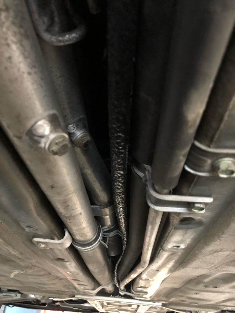
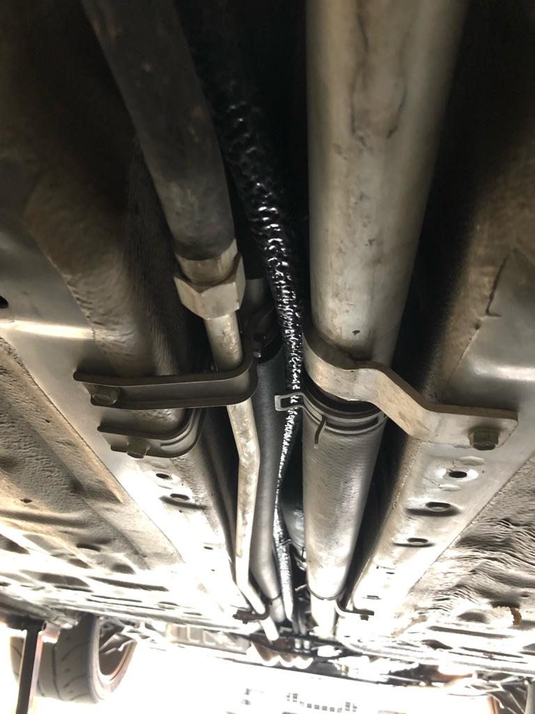
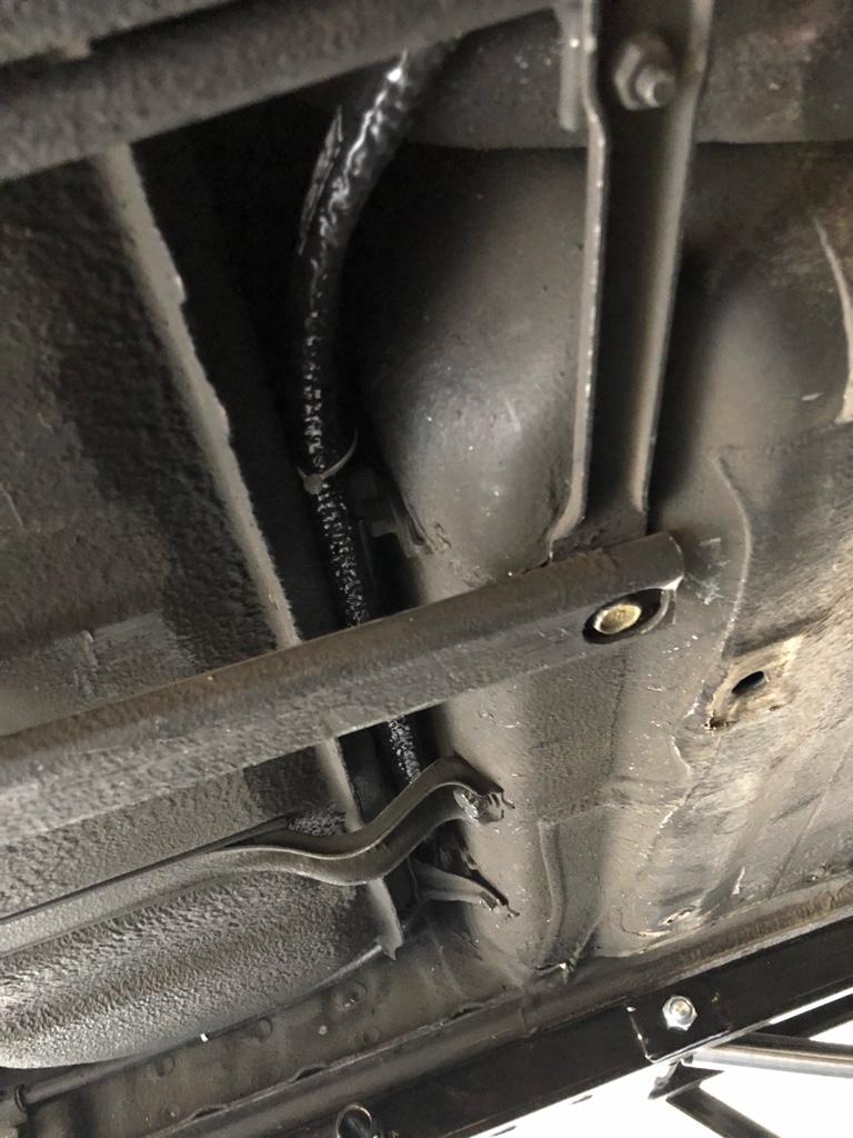
I'm currently in the process of installing a water / meth kit.


Water / meth kit

Before I bought anything, I did a ton of research. Really hoping the feds don't show up to the house for all those 'meth' google searches. I guess I should put a hold on any sudafed purchases for now...

There are a million kits, the option to piece together your own kit, and generally a ton of considerations, so it took a while to get a hold on what I wanted. The main things I was looking for were: simple and reliable once installed. This is a whole new system, which means opportunity for bugs and maintenance.


Spray n pray

Okay, where to start? There are basically 2 approaches companies take to controlling the spray:

PWM the pump. This is the most common approach. All companies other than Aquamist do this: AEM, snow performance, devils own, etc. This gist is that the nozzle is directly tied to the output of the pump, and the controller varies the pump speed to vary the spray. It's kind of a crude way to spray, but it obviously works; 99% of installs are using this approach. The benefits here are that the pump is only running when you are spraying. This makes sense for a street car which is rarely in boost. The downside is that the spray is not so precise, but based on my reading, it feels like super precision isn't really required with water injection.

Constant pump speed, PWM a solenoid at the nozzle. This is basically how your fuel injection works: keep a constant pressure, then vary the duty cycle of a solenoid to vary the spray. Aquamist uses this approach. There are probably some boutique controllers out there that do this as well, but I ignored anything that wasn't in a kit. The big benefits are that it's more precise, plus is generally 'safer' in that you wont have the nozzle leaking into the intake tract due to gravity, which is a common problem on the pump PWMing approach (e.g. read the AEM 30-3300 amazon reviews...). The downside to keeping a constant pressure in the lines is that you need to run the pump all the time, even when you're not spraying. Maybe not so practical for a street car.


Control

Beyond the actual pump & nozzle setup, what controller should I run? What parameters should I vary the spray on? Can I get away without a controller? e.g. Can I just deal with it in the ECU?

I really wanted to skip using a controller if I didn't need it. Say I had the eventual Haltech 2500, which has a built in water/meth function, would I need a controller? If not how do people set that up? The short answer: they (most people?) still use a controller by sending the ECU's water/meth PWM out to the controller. I didn't find anyone with a simple setup running from the ECU only. Maybe it exists, if you have seen it, let me know.

In any case, PWM out from the ECU into a controller was The Move, ideally such that I could vary the output from the ECU based on RPM and boost. You know, like a fuel map.

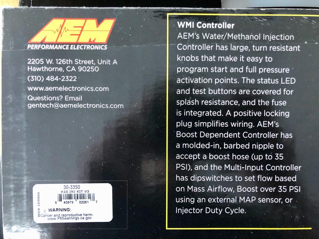
This narrowed it down to basically 2 options: Aquamist or AEM 30-3350. Both of them take one of the ECU's injector outputs as an input, and can be progressive based on injector duty cycle.

For a while I was sold on the Aquamist. The internet at large pretty unanimously regards it as the "best" WMI option. There are no reports of it hydrolocking any engines, it's controlled by injector duty by default, and the benefits of PWMing a solenoid at the nozzle were obvious. All good things. Buuut in the end I wound up with the AEM unit, despite AEM being right up there with Comcast on my list of top 5 least-favorite companies. The reasons:

* I didn't want to run the pump all the time. It was unclear if the Aquamist had a switch to turn the pump off when I wasn't using it, or if it was automatic. I dunno, seemed like some cognitive load there if I were switching it on and off.
* Aquamist requires that you run a gauge. I don't want no more gauges.
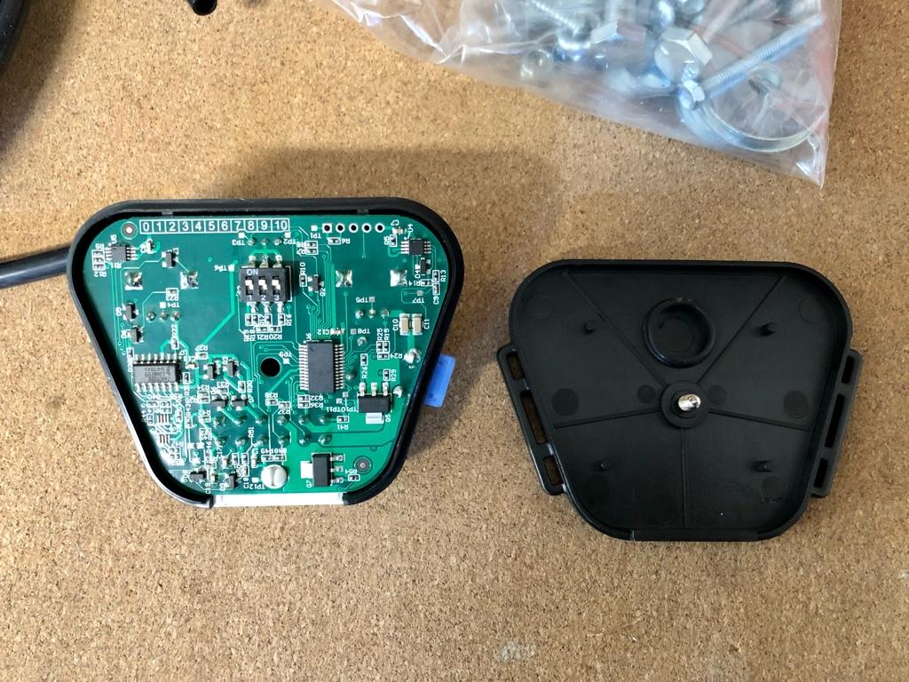
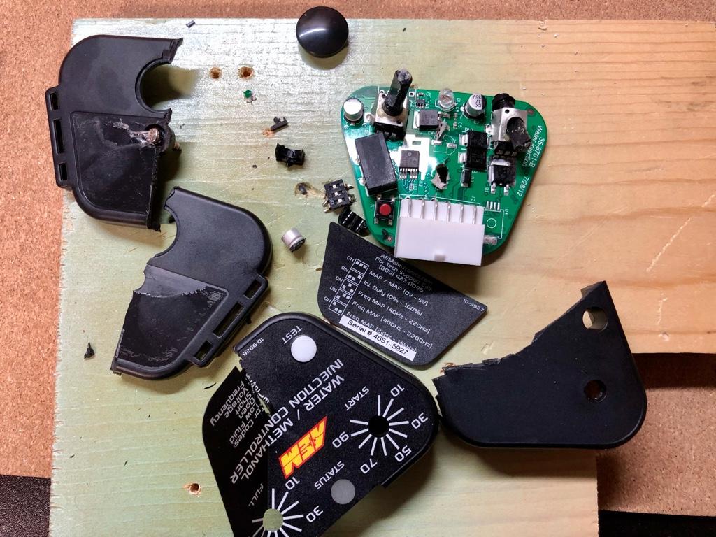
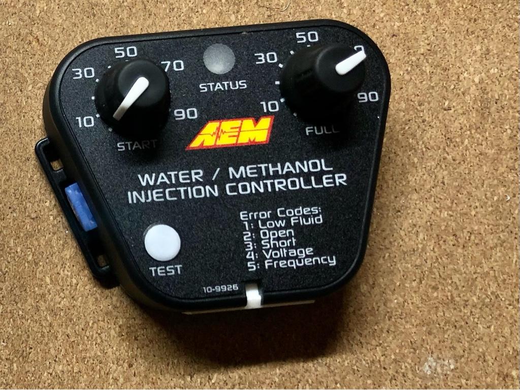
* Aquamist has built in 'maps' based on injector duty cycle. My plan is to control the WMI with staged injection from my AEM ECU, so I'd have total control over the map, and these built in maps would be annoying. The AEM controller is way dumber, which is nice. There is a knob for start duty cycle, and another for full spray duty. Easy, linear, and then I tune it in the ECU.
* Aquamist is like 1 guy, which made me nervous for availability and support reasons.
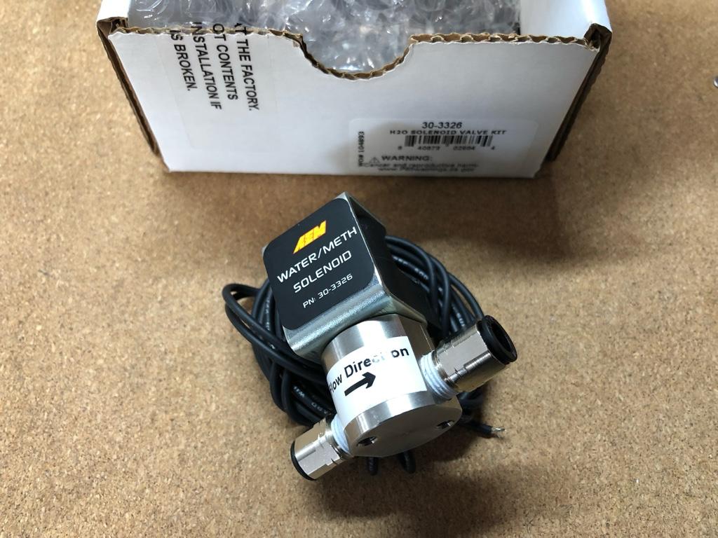
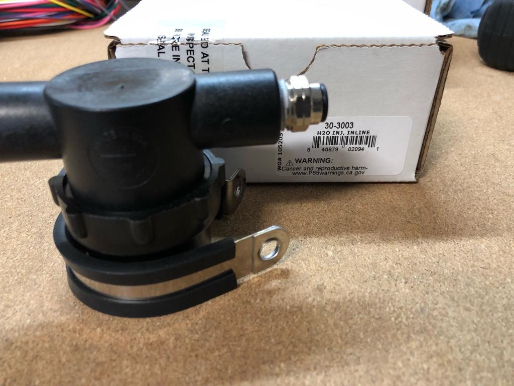
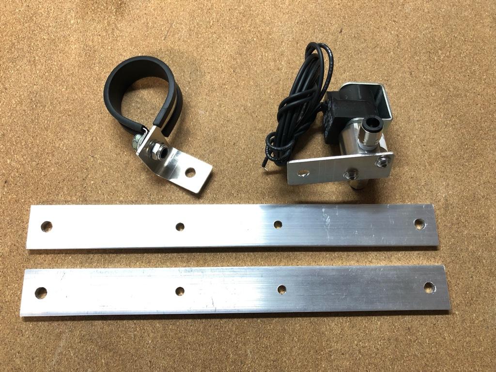
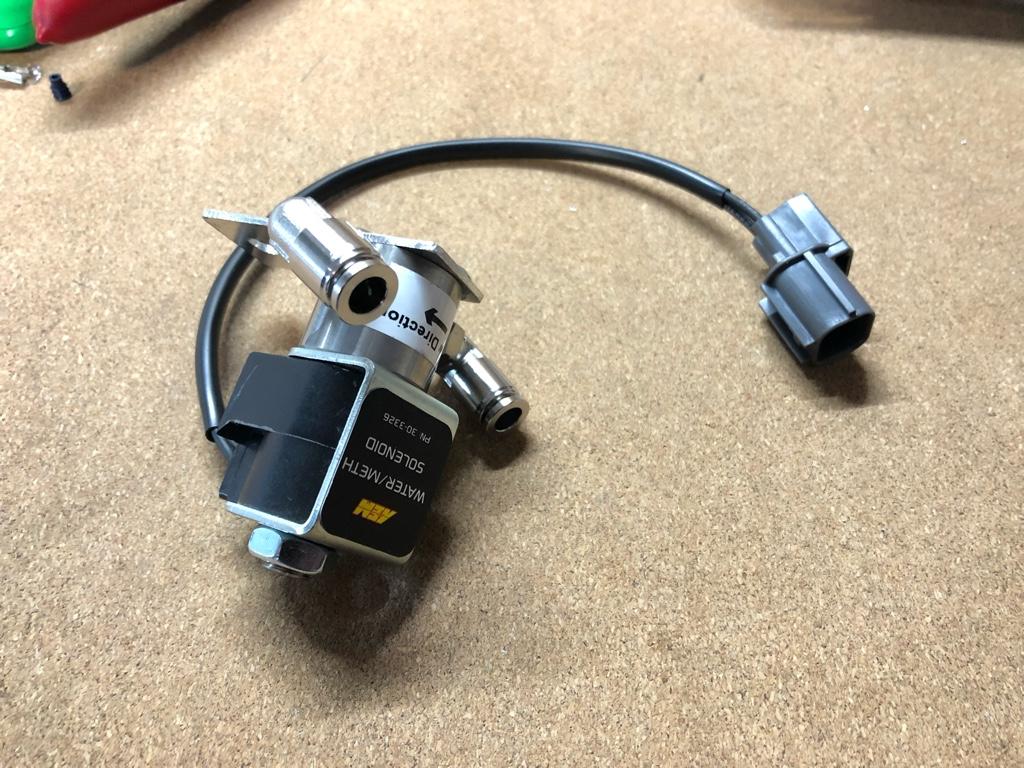
* AEM sells an optional solenoid to run at the nozzle that solves the leakage issue. It's cheap enough where it should just be included in the kit, I bet the amazon reviews would be a lot better if it were.
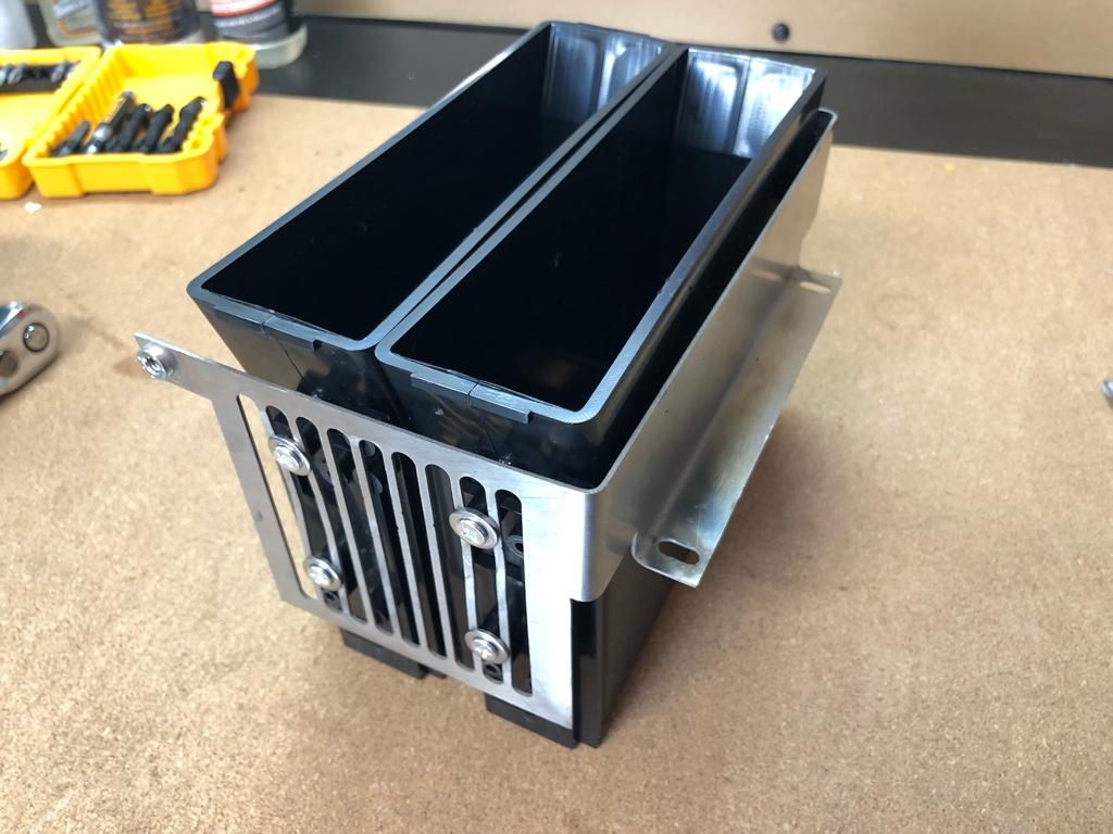
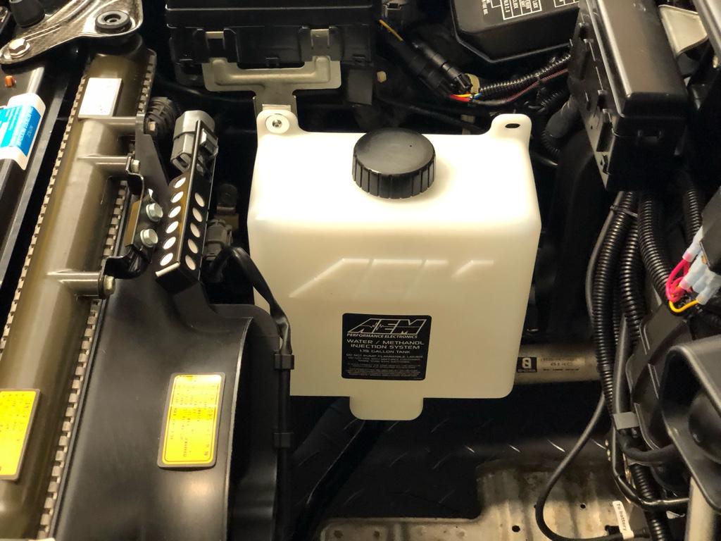
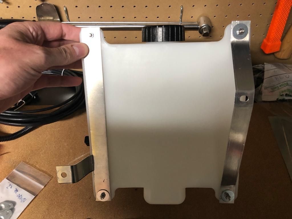
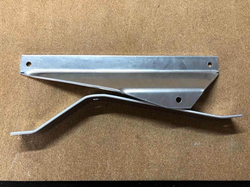
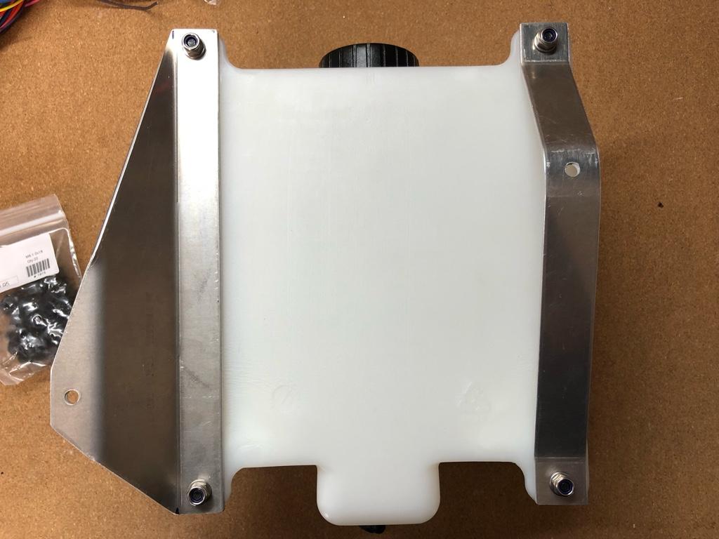
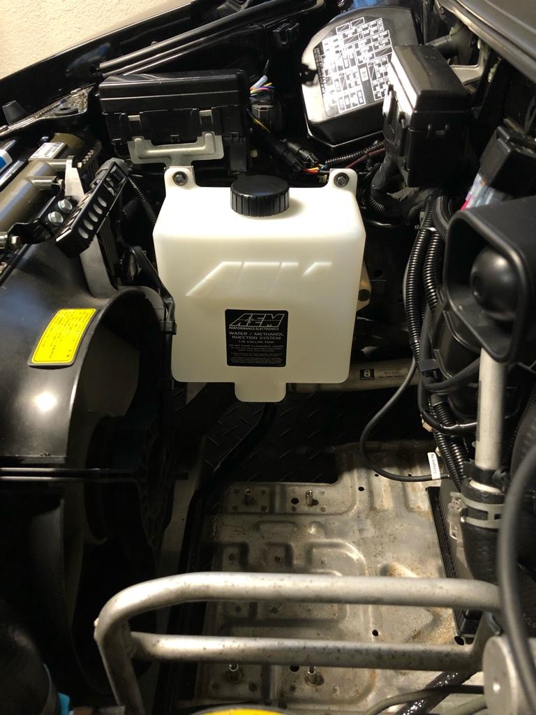
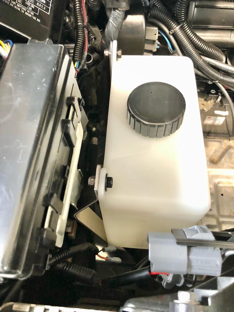
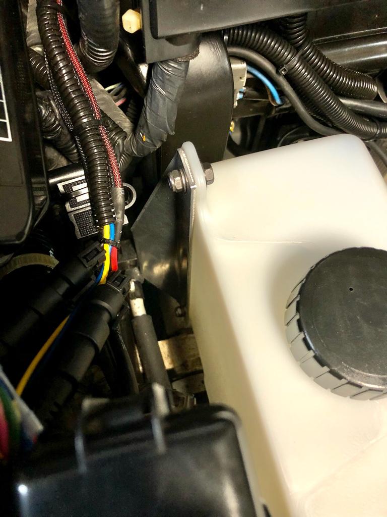
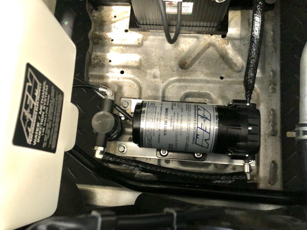
* The AEM tank actually fit in the space I wanted. I was planning on running the Aquamist baffled tank no matter what, but it is too long (13" square).
* I have it in my head that AEM's latest V3 nozzle is actually better in atomization than other nozzles out there. But It's probably just marketing nonsense I've internalized because I watched more videos with AEM stuff.

The verdict:

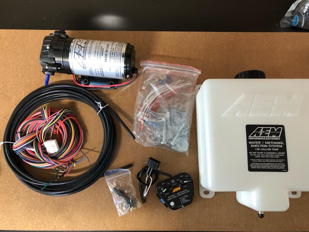
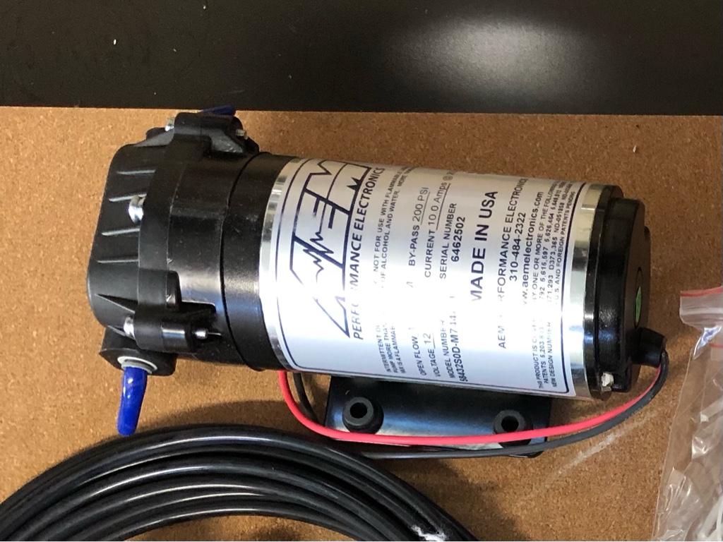
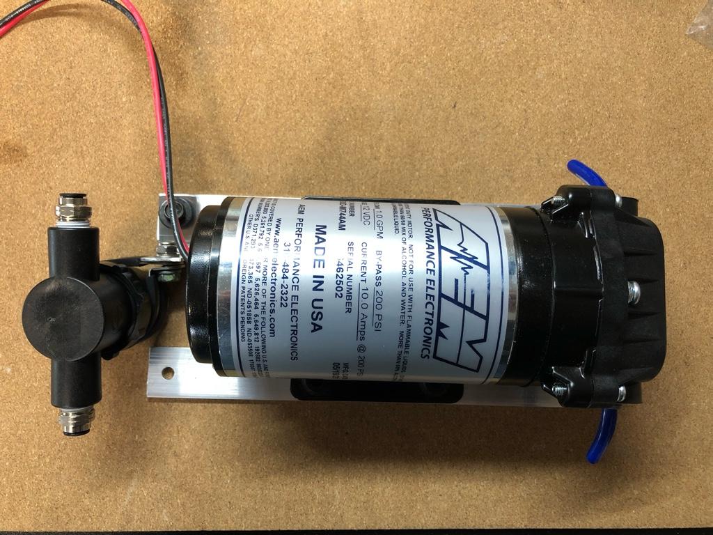
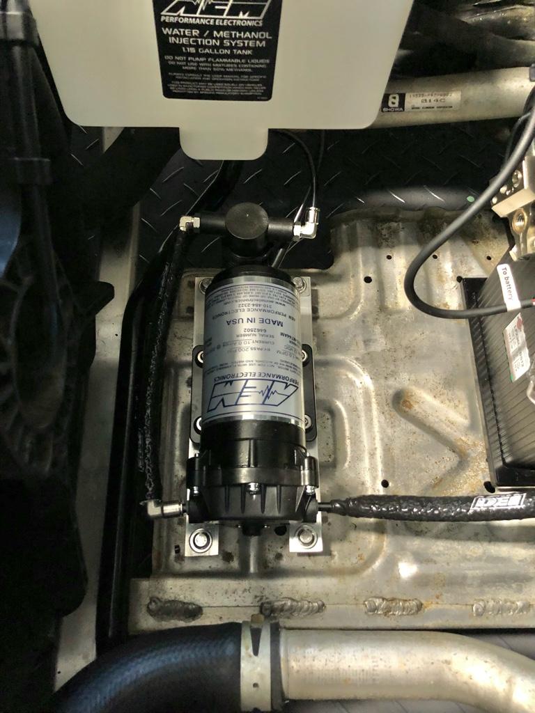
* AEM 30-3350, with optional solenoid and inline filter
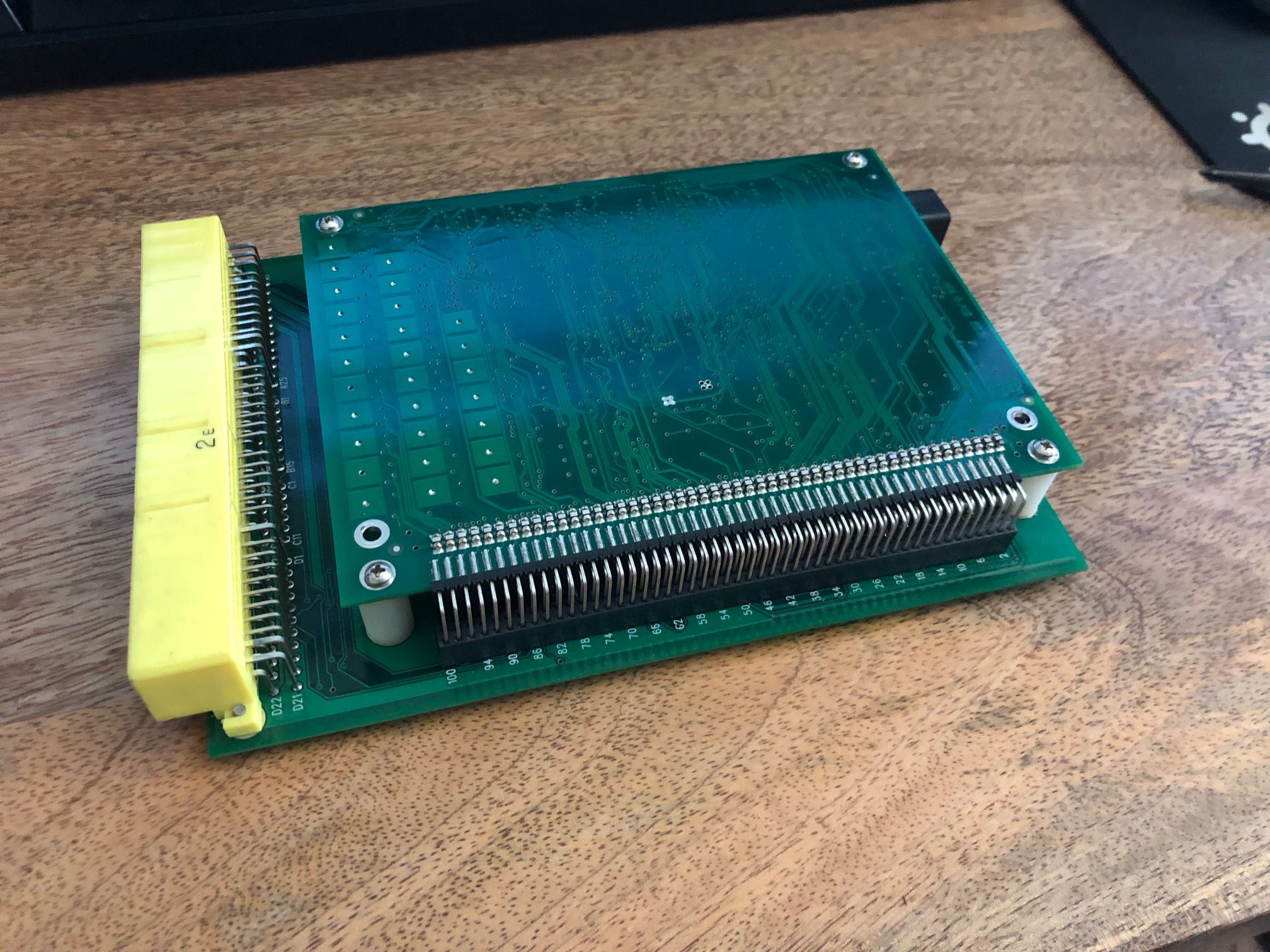
* Run it off the 7th injector output using the staged injection feature of the ECU


Where to spray??

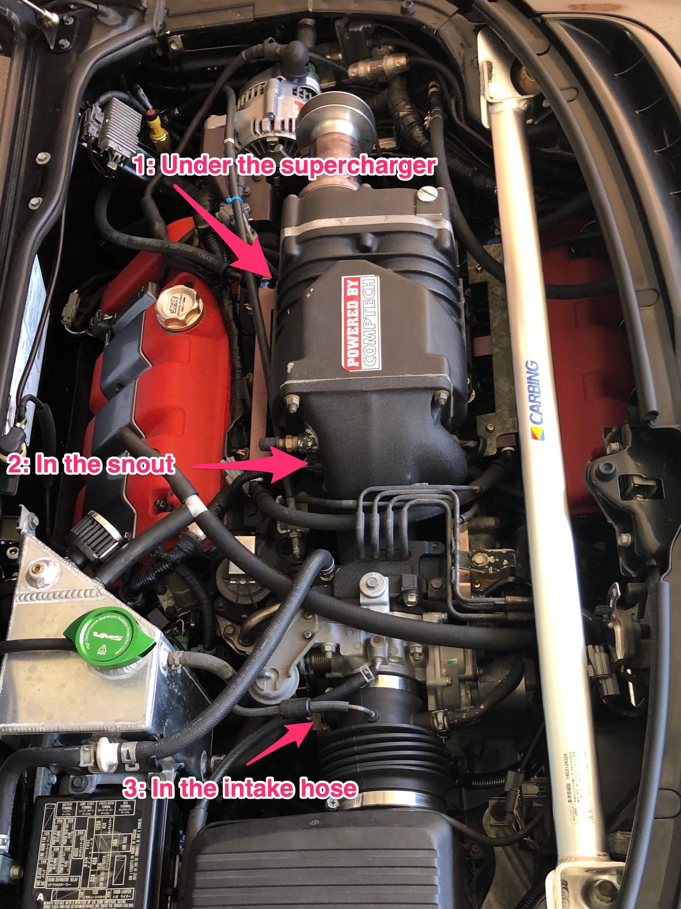
One of the many considerations is: where to put that dang nozzle? I wanted to sort this out before I bought anything. My location options in order of most desirable to least

1. After the supercharger. Install a sandwich plate between the SC and the manifold, put the nozzle in the sandwich plate. Mainlining the meth straight into the engine, it shouldn't waste any juice cooling down the metal bits like the SC itself or intake tract.
2. In the SC snout. Get a bung welded in on the SC snout and run the nozzle after the throttle plate. It's a pretty straight shot into the SC.
3. Before throttle-body. Similar to the SC snout way, but probably absorbs more heat before it gets into the manifold.

140625140-15679b18-b1b1-4393-8c5d-7bf47e8dbfd6.jpg


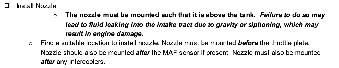
Unfortunately those options are also in order from hardest to easiest. I know the NSX community has a strong preference toward the post-SC sandwich plate. But the rest of the world tends to run the nozzle pre-TB. In fact the AEM instructions mention, in bold, to put it before the throttle plate.


140625082-5972ab4b-5ce1-4723-8414-72793e3245bc.png


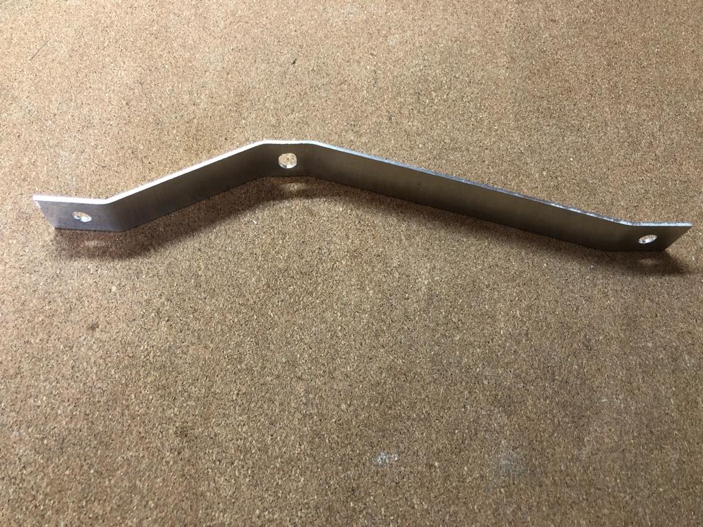
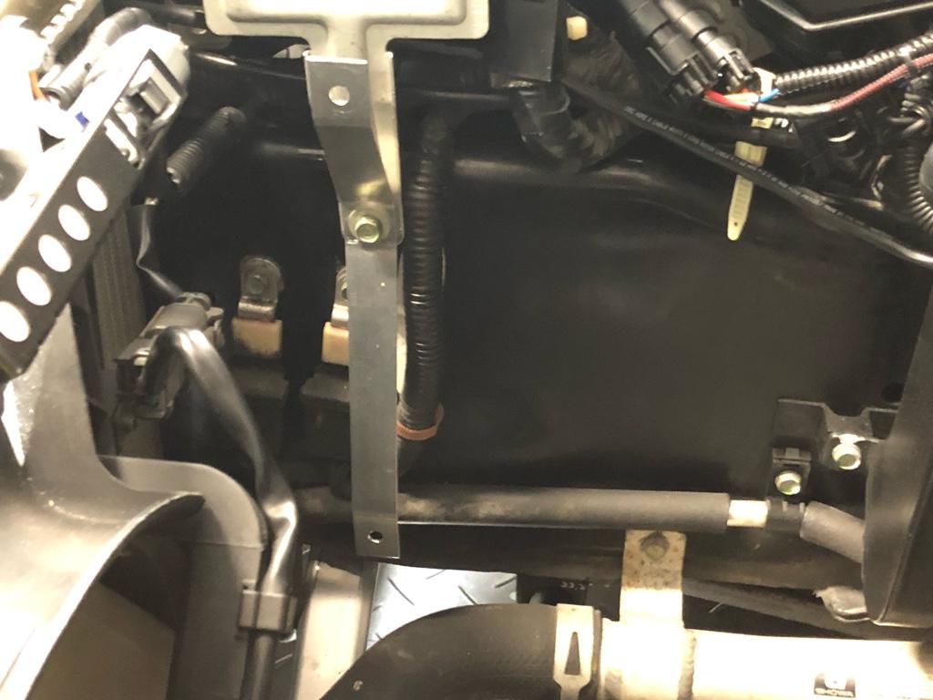
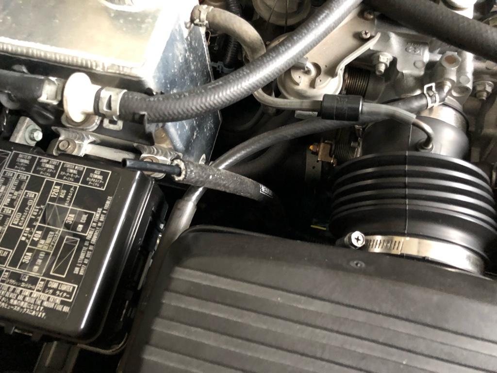
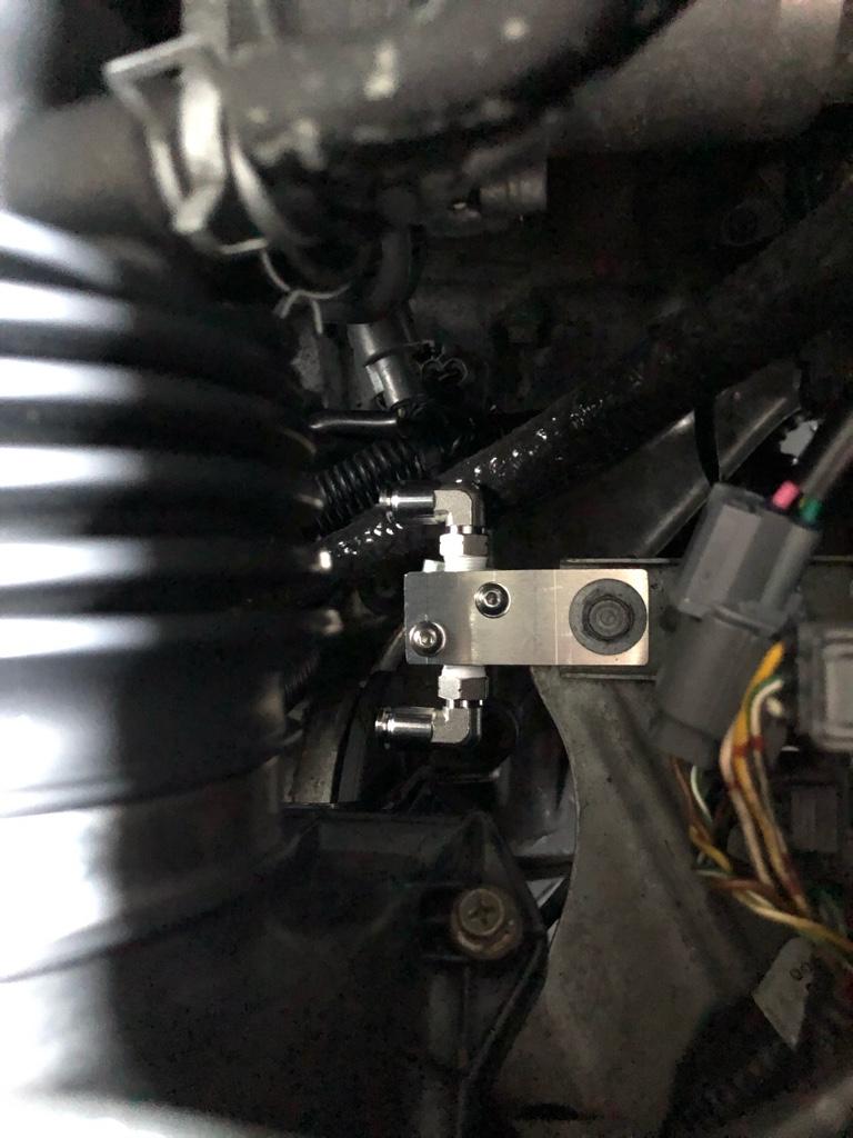
Because it will be so much easier, I'm going to run the nozzle in the silicone hose between the airbox and TB. The jury is still out on exactly how I'll mount it, but I have a couple ideas and some parts in the mail. If it sucks and I don't get great temp drop or stabilization, then I'll consider the harder options.

What about the rotors? Can you spray into the SC? After reading a bunch on the internet, I'm not super concerned with it. Nearly all SC setups with WMI injection spray into the supercharger, and there doesn't look to be any major drawbacks. The rotor coating may be stripped faster, but even that doesn't seem like a problem. I'll mostly be running water, so maybe less of an issue?
 
WMI Unboxing & Tank Mounting

I bought AEM 30-3350 V3, which has a controller accepting a MAP, injector, or MAF signal. They offer another one that requires you run a vacuum / boost line to it, but I want to have control from the ECU, so this was the one.

b09f94d0971e0a807acbb1d6697e6810.jpg


31aa8ec714f71f21cbe1f81fe6770bba.jpg


And the separate optional parts, solenoid (30-3326)

27354dab24fa5acb61597bb7e0fe3531.jpg


And inline filter (30-3003)

fdd249bc7a8f497600c796c95643ad54.jpg


It wouldn't be the full AEM experience without some back and forth with AEM support, though. The controller's back plate wasn't fastened; I took it out of the box and it just fell apart. Turns out the boss inside the case was broken, so the backplate's screw didn't catch any threads. Probably not their fault, I'm sure it was a shipping thing.

c18c12521a095fc9d9d25bc303cf25ee.jpg


They sent me a new one, but they made me destroy the old one. I honestly felt really bad. I'm sure the board was totally fine, I would have happily sent it back or accepted a new case. I asked a couple times, "umm, you sure?" They were sure. It was harder than expected, but a claw hammer and a screwdriver did the trick.

cc2c5eb8827d21e243a7899e85a976b5.jpg


And the new one. To their credit, it was quickly and painlessly handled:

60c56fcc8b5764751cb43aee4c00329b.jpg


Next up is tank mounting. I've been a bracket-making fool…
 
# WMI Tank mounting

First order of install business was figuring out where to mount the tank. I wanted to have the tank + pump under the hood. I'd looked at a bunch of pics of other water meth installs, and the cleanest setup to me was on the passenger side under the hood. So I went hunting for mounting locations.

There are 2 bosses on the frame rail that seemed pretty sturdy. The front one holds a relay bank, and the rearward one holds what looks like a drain pipe.

I made some measurements, made a quick bracket out of 1/16" aluminum:

0661a99fba801ec02517fc8e28356dc6.jpg


A test mounting. You can also see the other mounting point in this pic, it's the right-most bolt:

b561fbb324b0ffe42f8e003acc3771c9.jpg


Then with the tank on that first bracket to check clearance and things:

310a7a29c1b29ddfb30951dc647666d1.jpg


The second bracket was a more complicated and took a while to make as I have basically no metalworking tools. But I got it done. The tank with both brackets:

120d1ddc061146ed5f60b79533cf0d78.jpg


I bolted it up, but it was pretty flimsy. It probably would have been fine if it were just the tank, but it'll have 8lbs of water in it most of the time. The 1/16" aluminum was not enough, and the rearward bracket had a lot of flex.

I made some hasty drawings, sent them to my dad, and he made a set for me out of 1/8" aluminum. I wish the shop were closer.... I also changed the design a bit so the rear bracket would be gusseted af to combat the flex.

a2144c37a7daed8e78827fd468c99236.jpg


aadd8dd0ec1798d1067a3bef050ee1b7.jpg


And finally mounted!

a4fced1a746ec013d0c090aad9ced9d9.jpg


A closeup of the front bracket:

e578a9d53e25da5116ad77c2cfc922d7.jpg


And the rear bracket:

32cea0dfb67f00d6603de8fe99d3a48b.jpg


It's super sturdy now. One small thing I want to fix is the angles on the rearward bracket. They need to be bent a couple degrees more to put the bracket mounting holes in the center of the tank's slots. I notice it every time I look at the tank, but it is mounted! Some day (soon?) I'll have a vice in the garage, then I'll get a little brake attachment...
 
Water line install

The next thing I tackled was running the waterline from the frunk to the engine bay. I figured it would help inform how I mounted the pump on the battery tray. I wanted to use the tunnel as it seemed like the most obvious path from the front to the engine bay. The coolant runs through there, I’m sure if there were a world where the car had a factory WMI system, they’d have used the tunnel.

I was worried about the heat, though. Less so heat on the water line vinyl, but more so heating the water I’m trying to use to cool things down. I was semi considering running the line through the cabin just to keep it away from the coolant lines.

I reached out to [MENTION=28830]jwmelvin[/MENTION] and asked him a bunch of questions about his setup. He said he was using the tunnel and had no problems. The tunnel it is.

I was still worried about heat, though, so I did a little looking around at my options. Like can I wrap the line in heat tape? Do they make heat resistant tubing? Turns out yes. DEI makes this stuff called “fire sleeve” that is exactly what I was looking for.

I measured, added a couple feet as padding, and ended up buying 14 feet of 3/8” fire sleeve directly from DEI. I should have bought a 25 foot reel from Amazon as it was only like $10 more all in…. I also bought 3’ of 5/8, mostly cause it was the cheapest way to get some “fire tape” to finish the ends.

b5b065e10b61335134108594c012be88.jpg


a12d0c75b4ef7646d2fd57943ca174e1.jpg


I ended up running water line into the entire length of the fire sleeve before installing it. I debated back and forth cause I figured it’d be hard to trim the sleeve with the line in it. But I’m glad I did as it was pretty hard to run the line into the sleeve at about foot 10. It would have been impossible with the sleeve in the car and dealing with any curves.

f0d36d7eaffd28f9e7242a7f82028253.jpg


It’s a pretty straight shot on the drivers side of the battery, over the steering rack and into the tunnel.

From the front

3ab273a751a5a775e3c1a3d38711aacb.jpg


To the back

ba45b1007d98db5c542a6f92d7b21611.jpg


Then I ran it along side the driver’s side e-brake cable. Only 2 zip ties necessary!

53da0afc610a248f27048e138836278b.jpg


Then into the engine bay. I have a good bit extra in the engine bay so there are mounting options.

ad8d3c70dd53abc0af996a37bcc0e6ee.jpg


Next up: pump mounting!
 
Last edited:
Pump, filter, n solenoid

Alright. I got a tank, and I got a water line. Where does that pump go? What about that little leakage-blocking solenoid? Let me show you.

Pump

bc07ca842a96f7ccffe5b6c6b4d22025.jpg


Looking back at the pictures with the pump installed, it looks pretty straightforward and pretty obvious, but it took me a long time to figure out orientation and exactly how to bolt it down.

Turns out the pump can be mounted in any orientation. Sideways? Sure. Upside down? If I can build a sweet bracket, I guess the sky is the limit. I had a couple requirements

* The line routing should be pretty straight. No tight radii, no double backing, it should look reasonably clean
* I can build a decent bracket with minimal pain
* Away from coolant lines if possible

Ok, maybe a frame rail? No room, firewall? Bad idea. I mean, the battery tray is the obvious answer. But what should it bolt to?

One thing complicating this was that I needed to mount the filter between the tank and pump.

05043e25bd10b01b0433c35d213ba7f7.jpg


Where should that go? I wanted to mount it on the frame rail hidden by the tank, but there wasn’t an obvious place to mount it. The only way seemed to be building a bracket that held both the pump and the filter.

I did a lot of measuring, drew up some complicated brackets, but ultimately settled on a simple thing made from 2 pieces of 3/16”x1” flatbar I had laying around, plus some standoffs mounted to the spare tire studs on the battery tray. Then I made a quick 90 bracket to mount the filter

The brackets. It turns out the y distance between the battery tray studs are exactly the same measurement as the pump mounting holes. All the holes are in the center of the flatbar.

800793dd8feebad828f0c6d62e0062e1.jpg


Mocked up with the filter.

d86708626c6c9da0c91c226fbc53e35a.jpg


Then the standoffs. I used M6 x 20mm stainless standoffs. I got some stainless 16mm bolts as well

9d092c89460cc79c8d0d9f841f3a8dc7.jpg


Mounted standoffs

23b2f9a57f559eea7cef819c24a1e306.jpg


Ohkay, almost there. Cutting tube with my little tube cutter is super satisfying for some reason

daa44b473938118f780f9a8b046184a2.jpg


And mounted.

0c74fd39b30def1fb60342d91c0a9a6b.jpg


8e95975911522ee2593cf1c962c1745a.jpg


I have since shortened the front tube so things are more even, but that’s the gist.

Solenoid

This project a lot bigger than I anticipated. It has a ton of things to mount. Wheeeerrrree does this thing go? It needs to be in the engine bay close to the nozzle, but of course, where? I mocked it up in several different places. It made the most sense on a bolt behind the intake tube near the map sensor. I made a little bracket, replaced all the fittings with stainless elbows, and connectored it up so it feels semi OE

4e0cae9b64592440c138d3d883c42973.jpg


Mounted!

626228d9b9658fb6766a14db4e32dc49.jpg
 
Back
Top