Need diagnosis for my wacky tachometer

Joined
11 October 2016
Messages
168
Location
Ohio
Car is a 92 nsx manual with low miles. Tachometer works and appears to read appropriate at
idle but as i accelerate to redline the fuel cutoff and tachometer are not in sync. The tach upsweep is steady but slow and only gets to 5500 when the rev limiter is reached. I did change the igniter as i had an extra as i read it receives a signal. Should i send out for capacitors or is this something the calibration pods can compensate for. Very little on the forums when i search. Much appreciated
 
Please confirm that you feel the fuel cutoff is really happening at around 8k, and that the fuel is not cutting off at a real 5500, regardless of what the tach says. There are safeguards built in to prevent full 8k redline. If it's truly getting to 8k but the tach is not showing that, it's as you describe; something wrong with the tach or wherever it gets it input. If the tach is reading correctly and the fuel cutoff is occurring at a real 5500, then there's a different problem. You should be able to tell: 8k on a 92 manual in second gear is around 81 MPH. If you get fuel cutoff at 55 MPH in second gear, the tach is not off, there's a problem not letting the engine go to redline. Not sure from your post which is actually happening.

P.S. Apologies if this seems condescending and pretty basic; not my intent as it seems from your post you know what you're talking about.
 
Last edited:
Yes, my post was not very clear, fuel cut off is right at about 81-82 miles an hour in second gear, according to the gear ratios for the given speed for my 92 it's getting all the way to redline but just the tach doesn't seem to be reading correctly , this was never noticed on the pre-test sale drive as the engine was never taken to redline
 
Should i send out for capacitors or is this something the calibration pods can compensate for. Very little on the forums when i search. Much appreciated

Are you talking about the capacitors on the display cluster circuit board and the calibration pots on that board? If so, it might be drifting / failing capacitors causing your problem and if you do replace the capacitors, you almost definitely will need to recalibrate the tach using the calibration potentiometers. Typical capacitors come with quite large manufacturing tolerances (>> +/- 10%) so the replacement capacitor that you buy probably won't match the capacitor you replace - even if the numbers on the can match - hence the need for calibration pots.

I think Kaz posted on this subject about a year ago; however, it may have been in the context of speedometer calibration issues / problems rather than the tachometer. But, same issue with the re calibration for the tach. My memory is fuzzy; but, I seem to recall that Kaz discussed a recalibration service; but, I also seem to recall that the recalibration service was in Japan.

The tachometer is a pretty simple device. The electronics are just a pulse frequency to voltage converter and the meter displays the resulting voltage as RPM. In the service manual, Honda provides the pulse frequency / RPM reading calibration data. If you are moderately handy with a little coding, you can get an Arduino for less than $20 and program it to generate an adjustable pulse output which you can then use to check the calibration on the tach. Failing that, there are tach / speedo restoration services; but, my take is that they seem to be oriented to the vintage set, so I don't know whether they do electronic tachs & speedos. If they do the electronic tachs & speedos, then they will almost certainly be set up with a pulse generator for calibration purposes, so that may be an option.
 
Last edited:
OK, I should send in the cluster for capacitor replacement and I'll start searching for someone that can do the calibration
 
Perhaps start with Brian K - NSXErepair
 
Update. Cluster almost out but before i send it out i wanted to confirm its not a simple calibration issue that i can adjust with the pots on top of the tachometer. I was reading in an old thread that i could pick up a tach signal from a connector on the left side(drivers side) of the engine bay. Can someone point me towards the connector. I have a multimeter and based on tach signal output 100Hz was equivalent to 2000 rpm.
 
Check page 11-84 in the 1991 service manual for the location of the service loop or the tach connection in the engine compartment. However, a multimeter will not do the trick. You need a proper tach, and one with an inductive pick up if you are going to use the service loop.
 
Don't have a clue. The wiring diagram in the service manual does not show where the tach connection test point comes from, so I don't know whether it is switched 12v off the coil winding primary (which is what old school needs) or whether it is logic level directly out of the ECU.
 
It is a 12V square wave

Is it a conditioned (true) 12 v square wave or is it the switched 12 v that you get on the primary of an ignition coil (which has all sorts of nifty voltages in it)? If it is a true square wave, the old school tach may not work. If its the switched 12v signal off of one of the coils, the tach may or may not work. The OP might have to do some mental arithmetic depending on what the pulse/RPM rate is for at the test point.
 
Is it a conditioned (true) 12 v square wave or is it the switched 12 v that you get on the primary of an ignition coil (which has all sorts of nifty voltages in it)? If it is a true square wave, the old school tach may not work. If its the switched 12v signal off of one of the coils, the tach may or may not work. The OP might have to do some mental arithmetic depending on what the pulse/RPM rate is for at the test point.
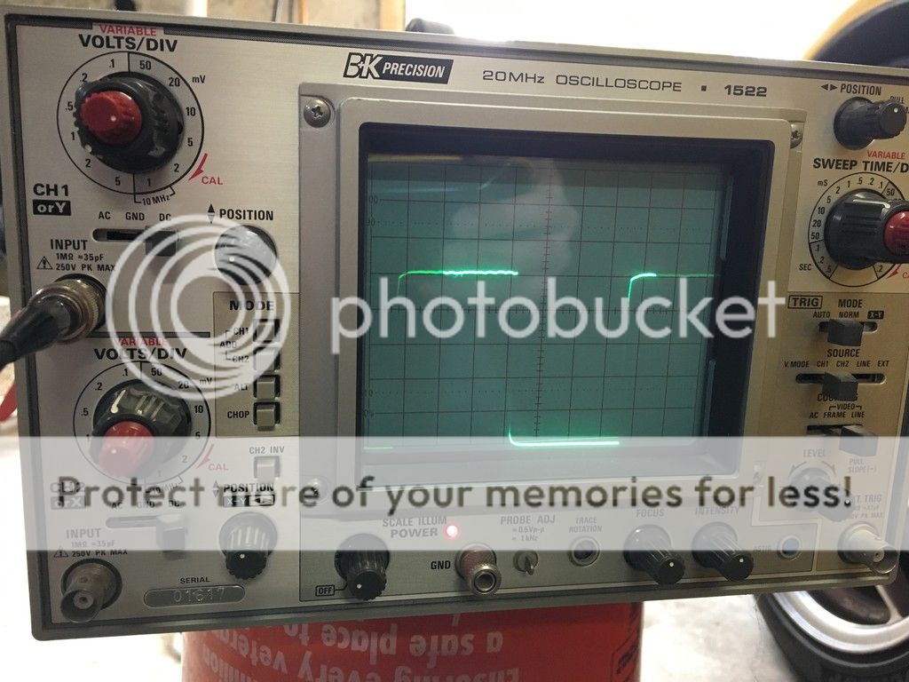
I figured I should go ahead and figure out the answer. It looks like the signal is actually a 10V square wave (not carefully calibrated or precise, but checked the oscilloscope against a DC voltage measured with a voltmeter first). It's a clean signal. Here's a picture:

IMG_1884_zpsrztsrge2.jpg
 
So my degree is in medicine, this is already over the top for me, could I get one of those cheap automotive multimeters that has a tachometer setting where you can select for six cylinders
 
So my degree is in medicine, this is already over the top for me, could I get one of those cheap automotive multimeters that has a tachometer setting where you can select for six cylinders
There's one easy way to find out. My guess is that yes, it will work. It does not take a complex circuit to interface with this signal.
 
The signal to the dashboard tach is calibrated at 300 pulses /minute at 100 RPM (jives perfectly with the 6 ignition events every 720 deg of crank rotation for a 6 cyl engine). If your multimeter / tach is set up for a distributor type ignition system, it will also be looking for 6 ignition events every 720 deg of crank rotation on the 6 cyl setting. So, if the tach test point in the engine bay is calibrated just like the dash tach signal, you are probably good to go with the 6 cyl setting on the tester..

In post #8 you made reference to someone discussing a tach connector on the left side of the engine bay. That would probably be the service loop on the igniter module which would require an inductive pick-up. If you know somebody who has a late model inductive pick up timing light, a lot of these timing lights now have a digital display on the back which provides, amongst other things, engine RPM. Could save yourself some hassle if you know anybody that can lend you one of these timing lights.
 
...if the tach test point in the engine bay is calibrated just like the dash tach signal, you are probably good to go with the 6 cyl setting on the tester..

The tach test point is the same signal as the dash tach signal.

In post #8 you made reference to someone discussing a tach connector on the left side of the engine bay. That would probably be the service loop on the igniter module which would require an inductive pick-up.

The connector is just behind the alternator and has a little rubber cap on it. Once you pull the cap off, you can insert a wire into the connector, which only has one pin populated. That's what I used to look at the signal earlier today. The rubber cap didn't want to come off but eventually it gave up.
 
I figured I should go ahead and figure out the answer. It looks like the signal is actually a 10V square wave (not carefully calibrated or precise, but checked the oscilloscope against a DC voltage measured with a voltmeter first). It's a clean signal. Here's a picture:

IMG_1884_zpsrztsrge2.jpg

B&K 1522! I have had a B&K 2120 in the basement for 20+ years. It looks like the same scope as the 1522, except slightly less maximum vertical sensitivity and they altered the control panel format to make it look more like a Tektronix. Finally upgraded to a 4 channel Rigol 50 Mhz digital storage scope last year just so I don't have to use a camera to take pictures of square waves! Still keep the 2120 around for emergencies because sometimes I can screw up the Rigol programing so badly that nothing works. Sometimes an on button that is just an on button is nice.
 
IMG_8911.jpg
I bought one of these on amazon. Around $30....I was able to pick up tach signal as described bythe gurus....idle is around 950-1000 but tach reads 1300. When true engine rpm is 2000 tach reads 1850, when true rpm 3000 tach reads 2700...true rpm 4000 tach reads around 3500.... you get the idea. Now how do the 2 pots work. Is there a low and high limit or is the tach toasted?
 
I think your initial inclination is likely good: replace the capacitors. We know that the capacitors go bad in nearly all of the electronics in these cars. So while you might be able to compensate for changed circuit behavior with the potentiometers, that would only allow the circuit to further degrade. I would replace the capacitors myself; I did the CCU caps recently. But I also wouldn't hesitate to play with the potentiometers.
 
One pot is for calibration of the speedo, the other for calibration of the tach. The electronic circuit in the tach is a moderately accurate pulse frequency to voltage converter (the tach meter being in effect a voltmeter). Because of the rather loose tolerances that go into the components, the circuit is provided with the calibration pot which is adjusted to provide a reasonable degree of accuracy. With the exception of the idle reading, your test results suggest that the dash tach is reading consistently low which you may be able to fix with the calibration pot. I really don't know what is up with the idle reading (other than the observation that your car seems to be idling really fast - normal warm idle on a manual shift is kind of 800- 900 RPM; but, that is a separate issue). So, you may be able to bring the tach into a reasonable degree of agreement with 'true' RPM with the calibration setting.

But, heed jwmelvin's advise. The tach's calibration has changed for a reason and that reason is likely drifting / failing capacitors. If you manage to get it back into calibration with the pot, you may find that in a few months or so that the calibration is changing again. At some point the capacitor problem may become bad enough that there is not enough adjustment available to compensate. I also notice that based upon your measurements, the tach does not have a consistent % error versus engine speed. It looks like the slope of the calibration line has changed. So, you may be able to calibrate the tach to give you an accurate reading at one RPM; but, the other RPM values may be in error. Go ahead and see if you can calibrate the tach; but, I have a feeling that you are going to be doing the capacitor thing at some point.

Final piece of advice. Before you mess up your cluster calibration, take your $30 tach and check its operation on another car. The fact that it is telling you that your car is idling at 950 - 1000 RPM makes me think that it may also be out of calibration.
 
Update. Capacitors done by Brian. Tach and cluster work perfectly. Much thanks to all of the gurus and I wanted to provide completion of this thread in case someone searched in the future. Btw. When warm idle is around 800 rpm and I confirmed this with my cheap tachometer It takes a while to warm up and I noticed that the engine tends to get much smoother when warm
 
Positive outcomes are nice. Did Brian calibrate the tach (and presumably the speedo) as part of the rebuild process or is that something you had to do?
 
Not sure. The speedo was near perfect based on a gps speed. The tach is about 50 rpm less than true which i kind of like. Allows me a buffer to stay off the limiter.
 
Back
Top