• Protip: Profile posts are public! Use Conversations to message other members privately. Everyone can see the content of a profile post.

***STICKY*** - Timing Belt & Transmission Rebuild Thread (2005 NSX 6MT)

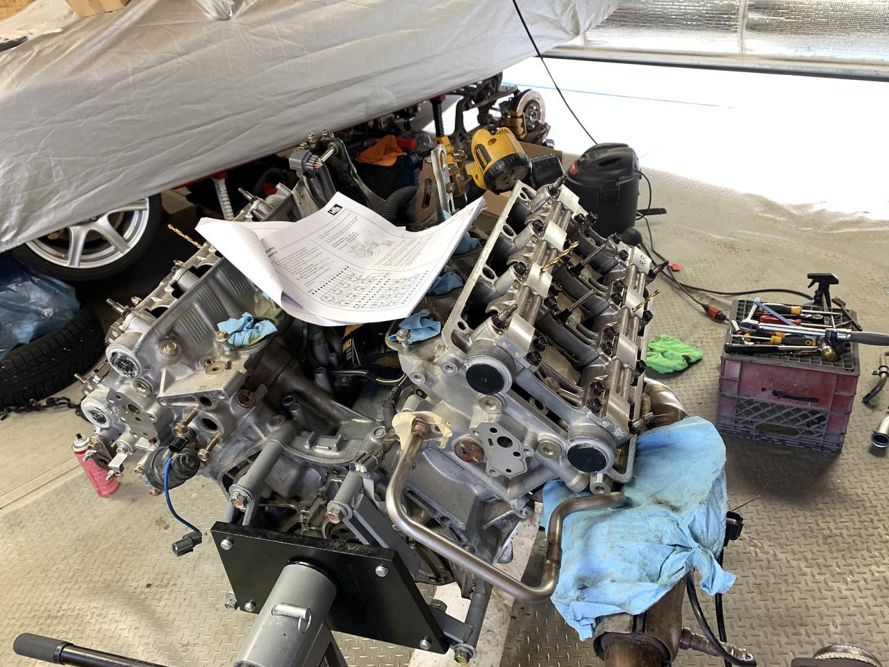
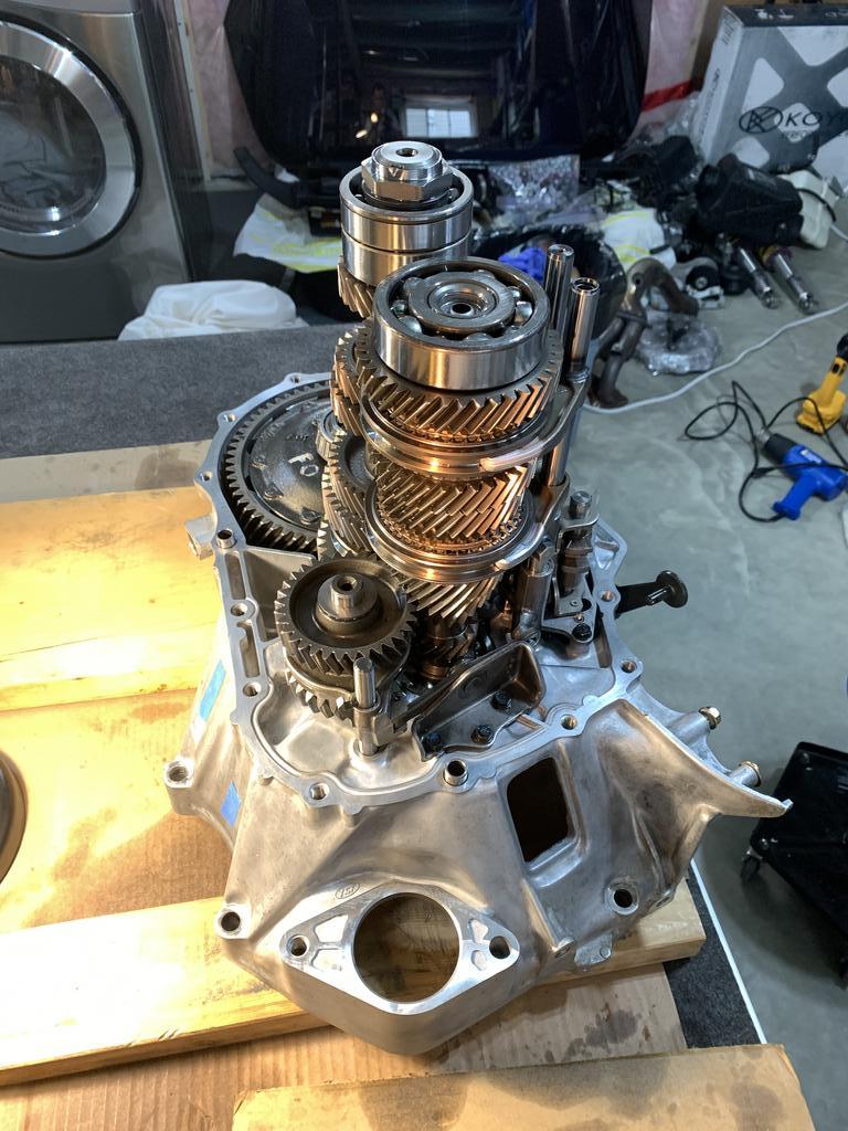
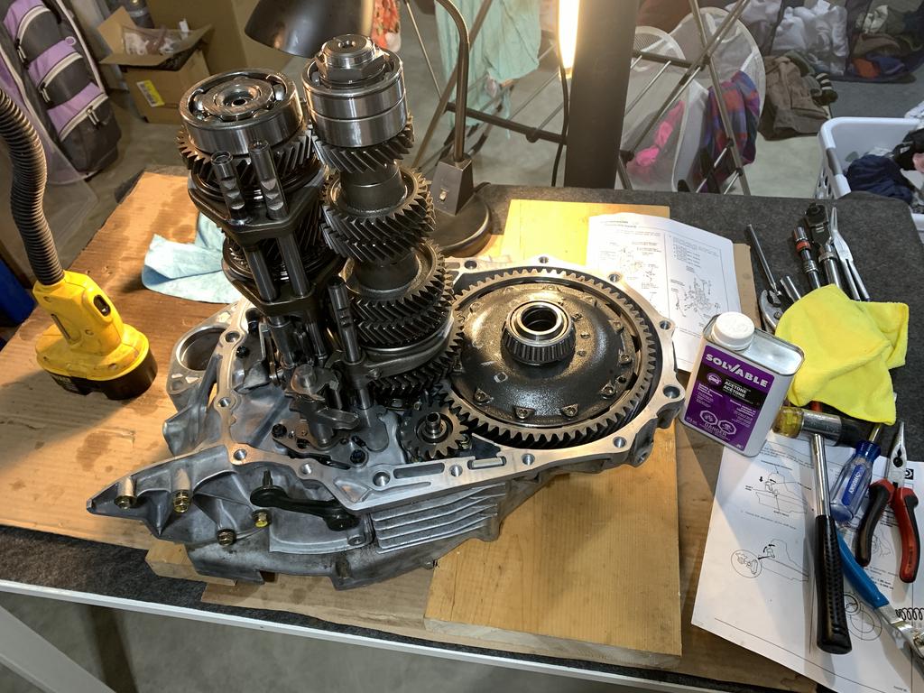
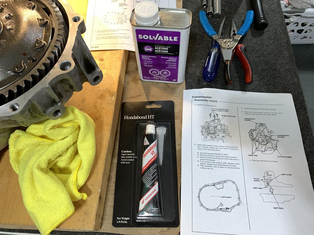
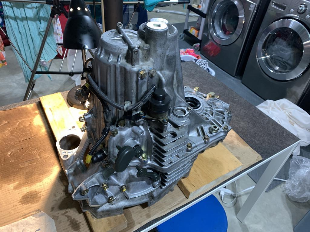
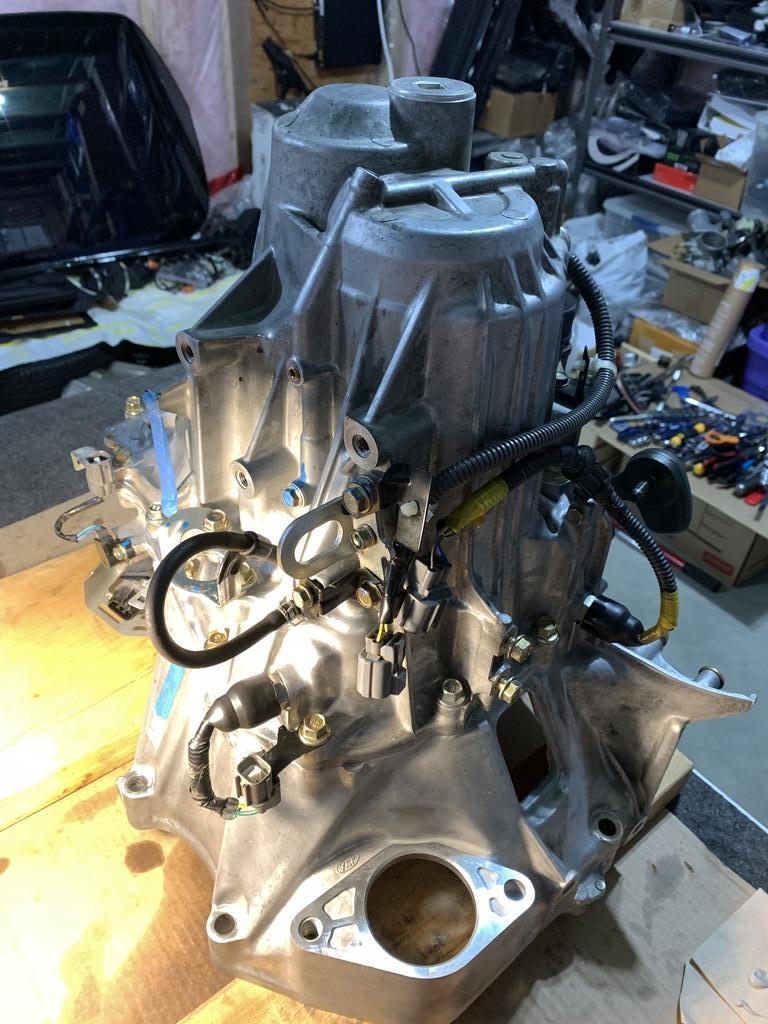
Now to start putting everything back together for the final time.

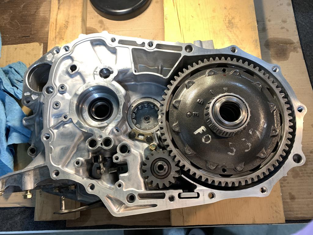
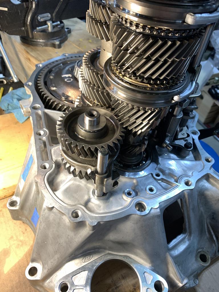
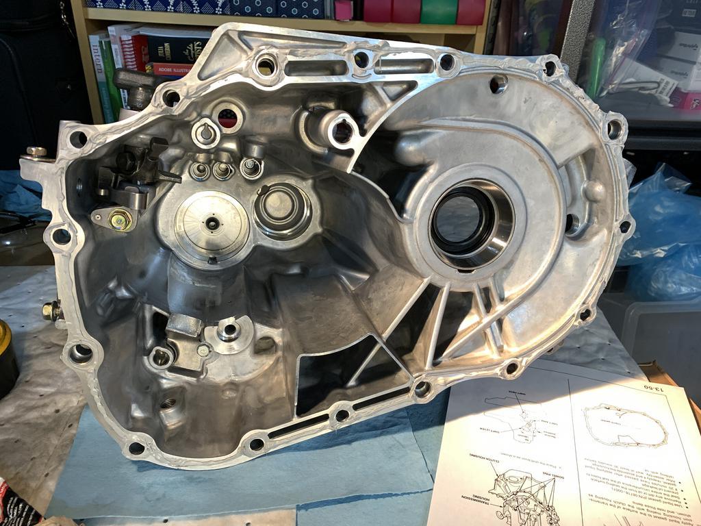
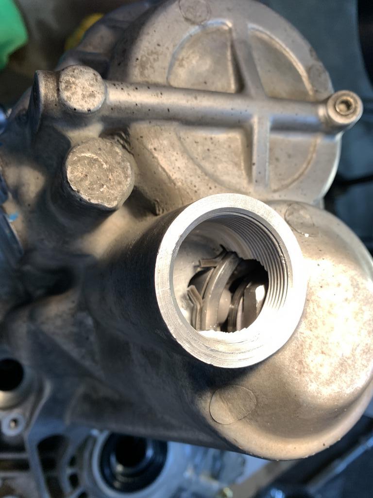
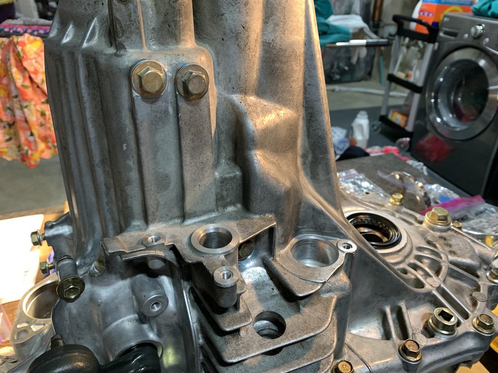
First the differential
O2sqeHF.jpg


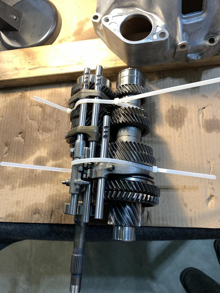
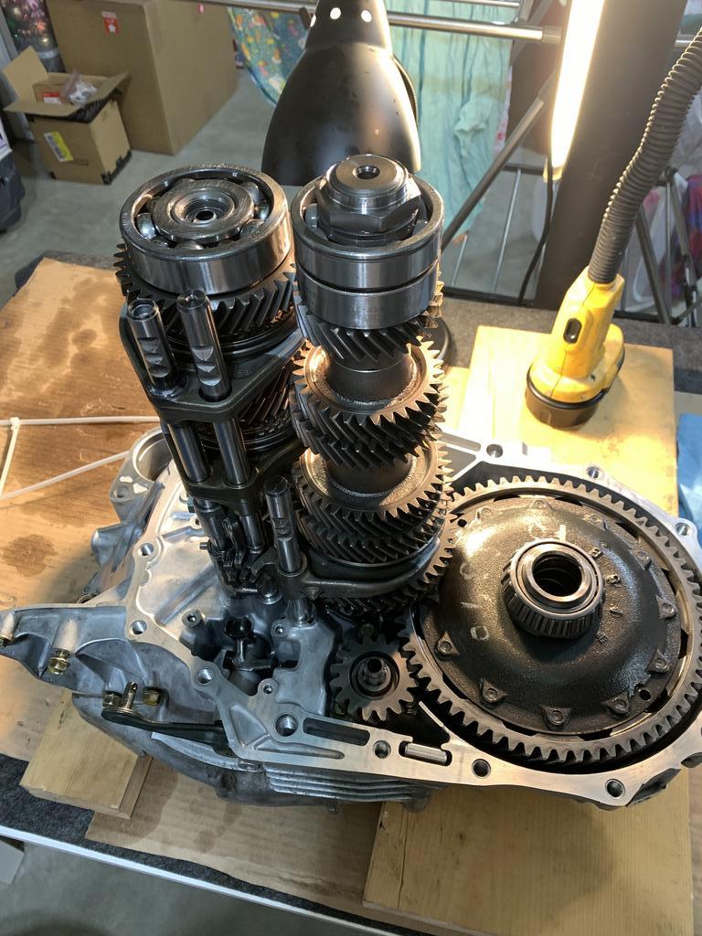
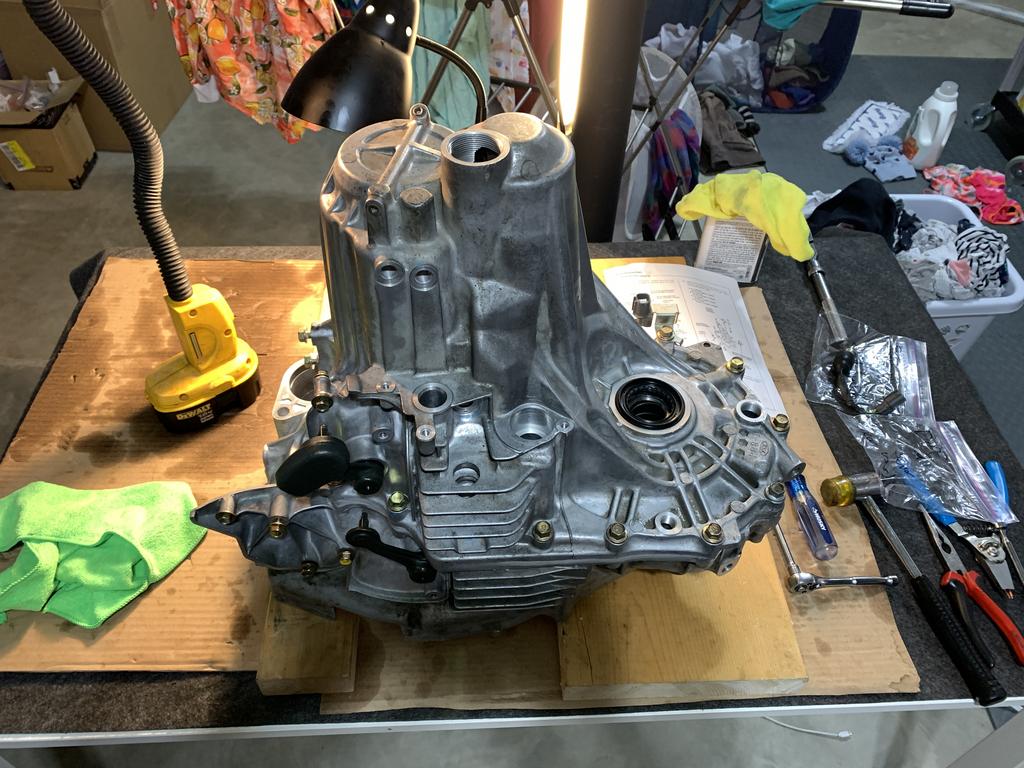
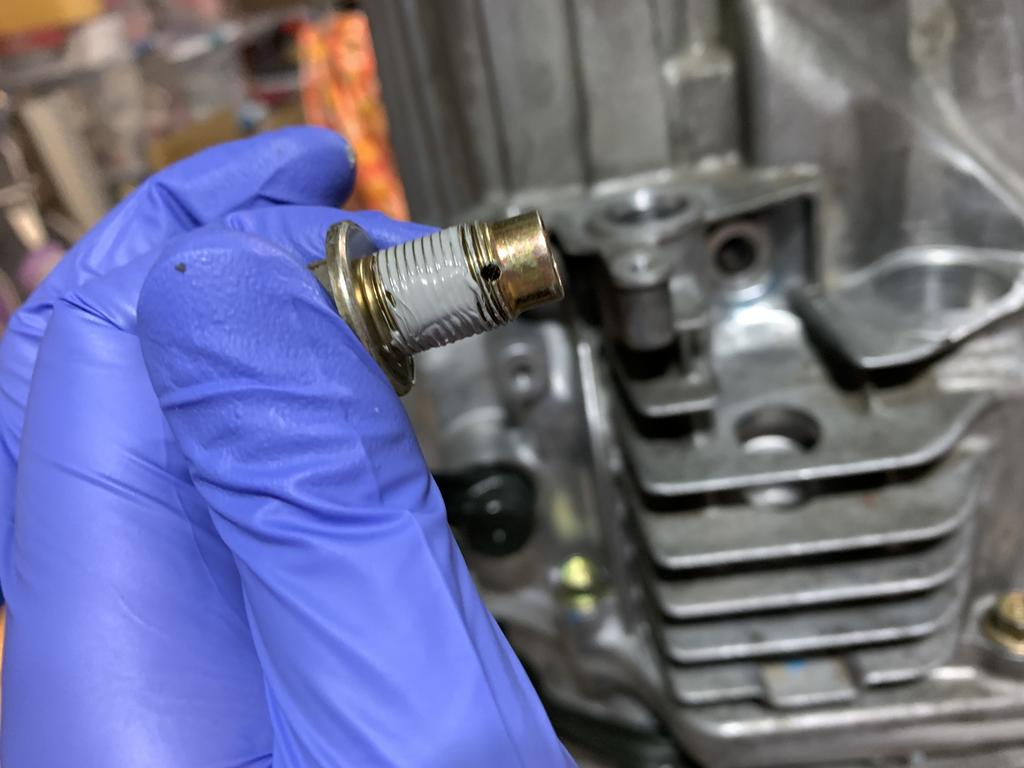
Then the forum approved zip tie method for the shafts and shift forks. I can honestly say it worked great.

WHgH854.jpg


XbCHSY4.jpg


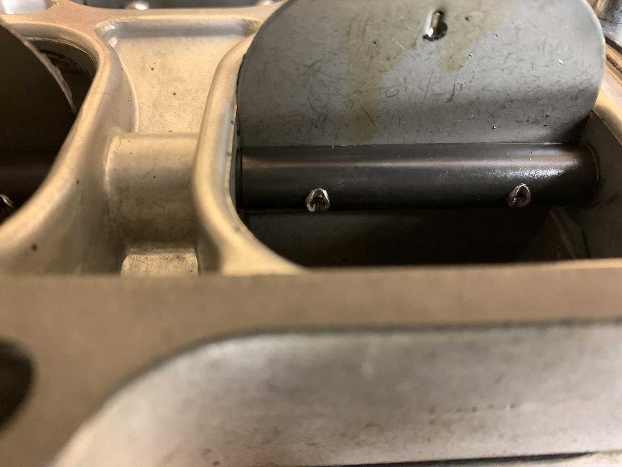
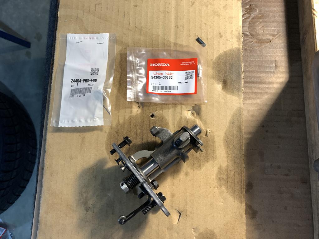
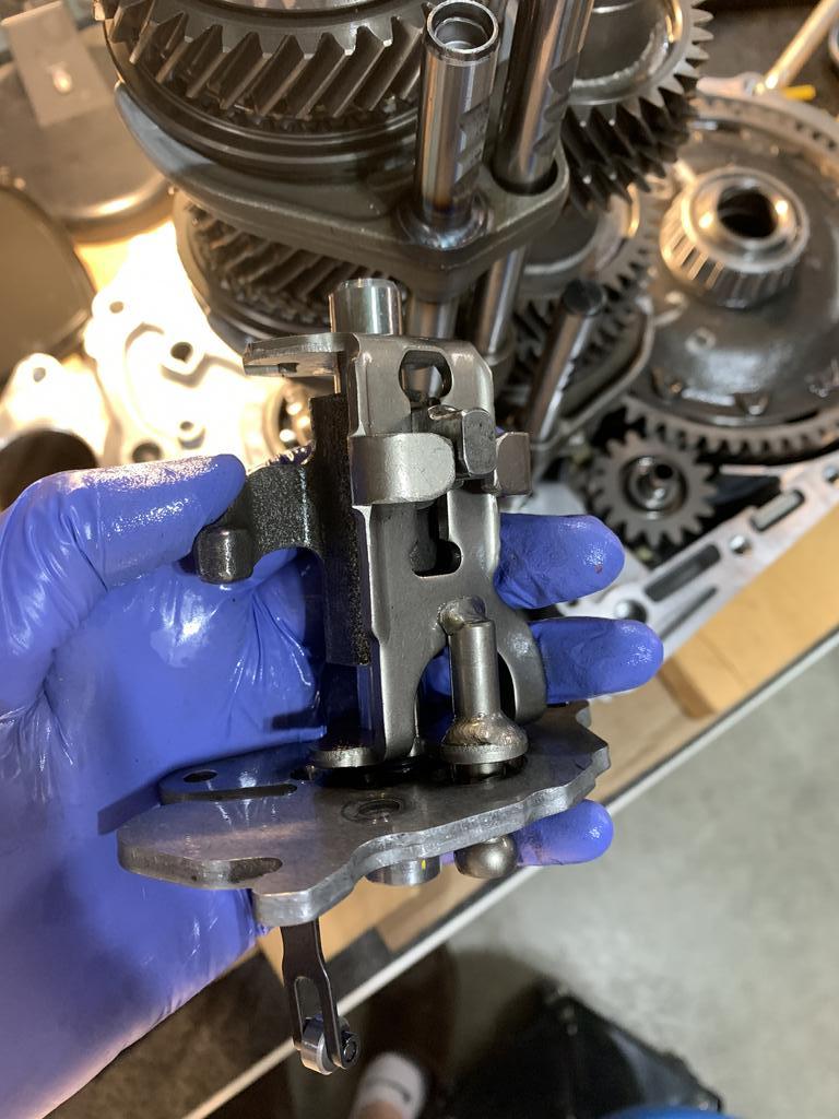
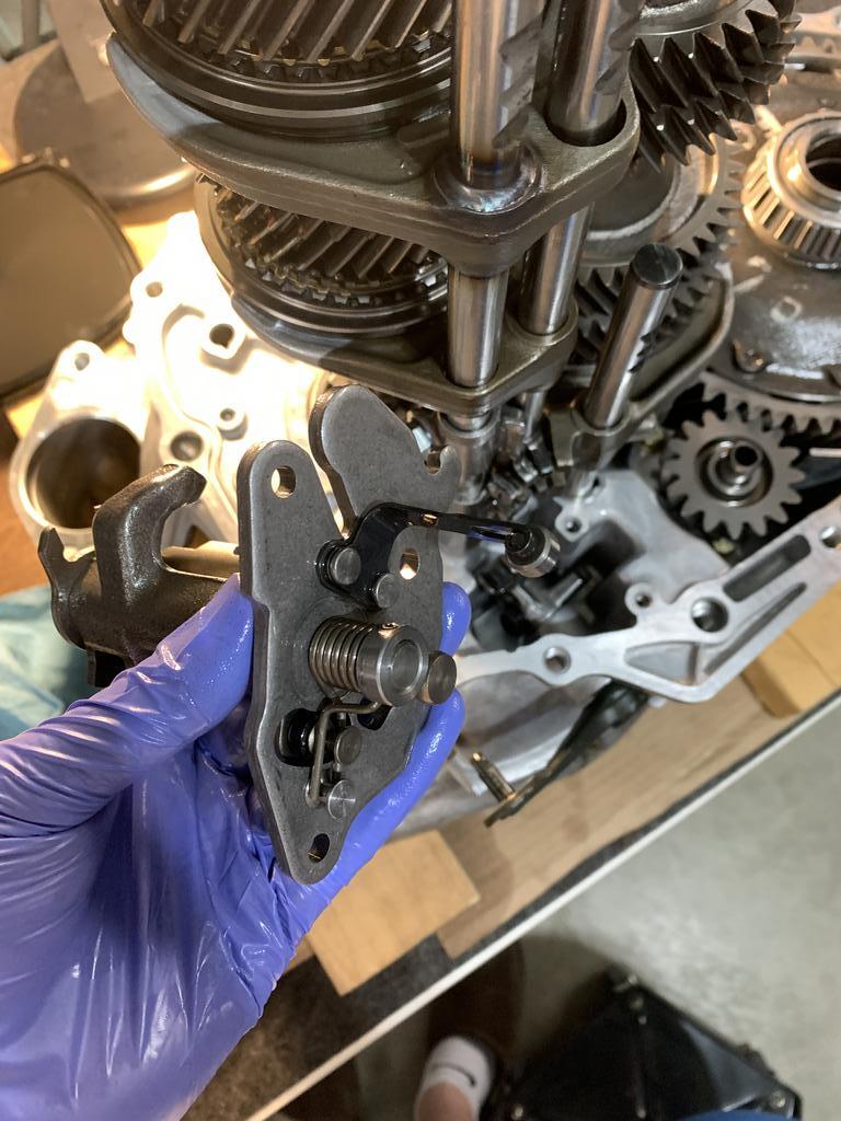
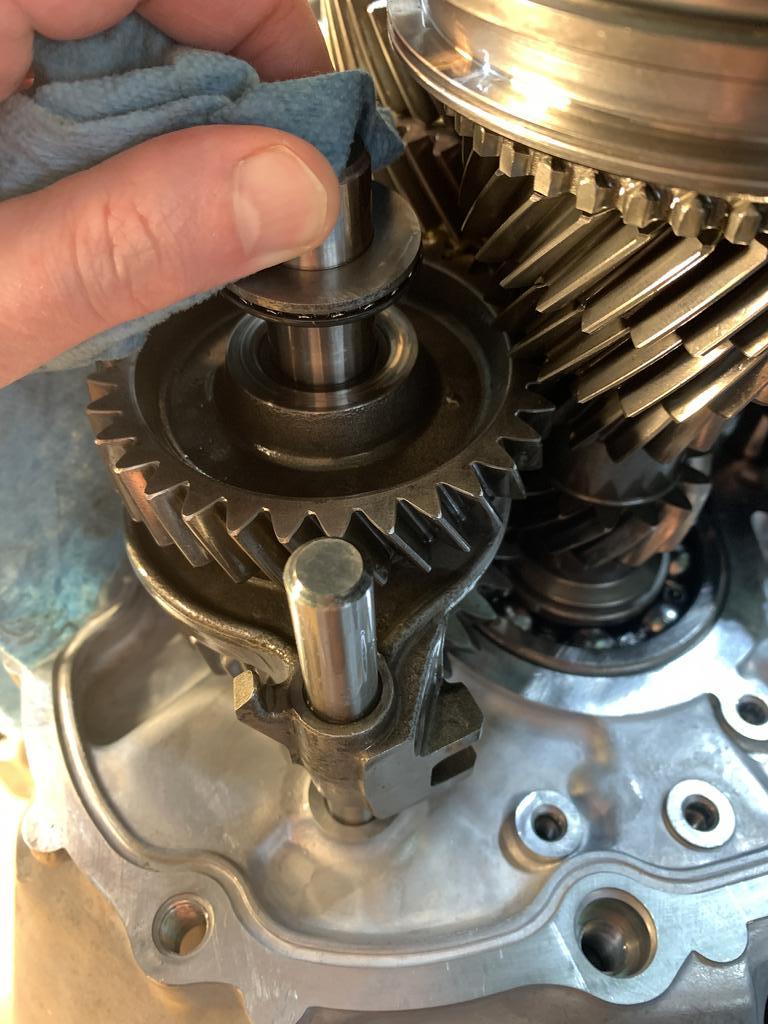
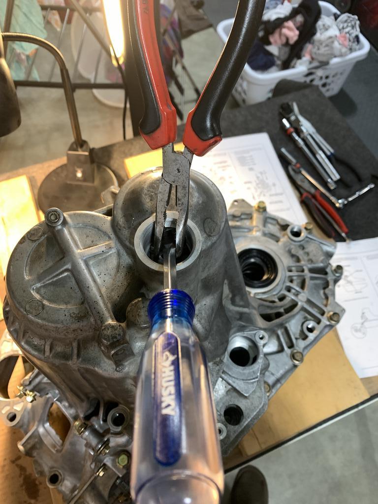
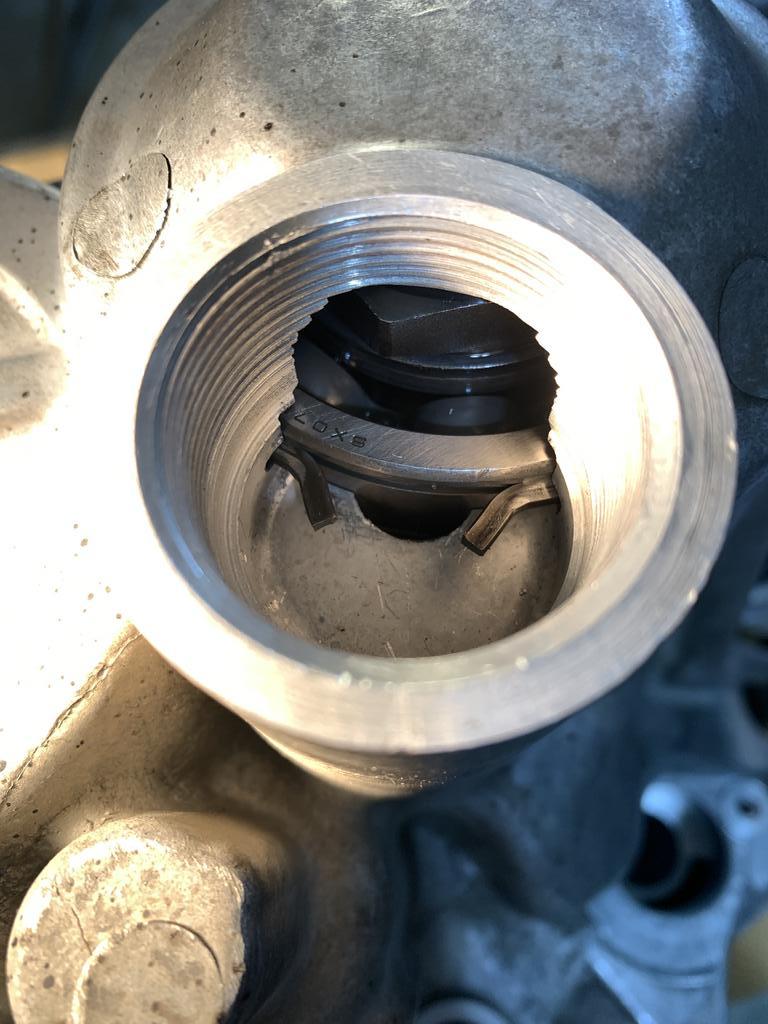
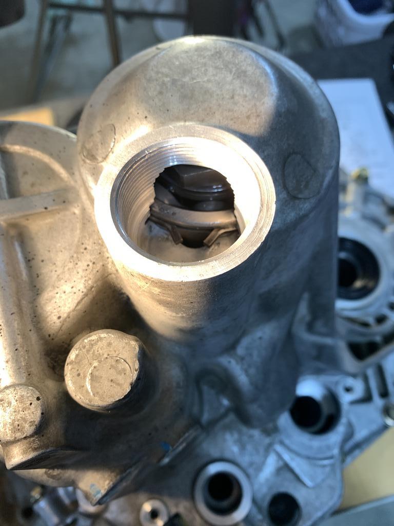
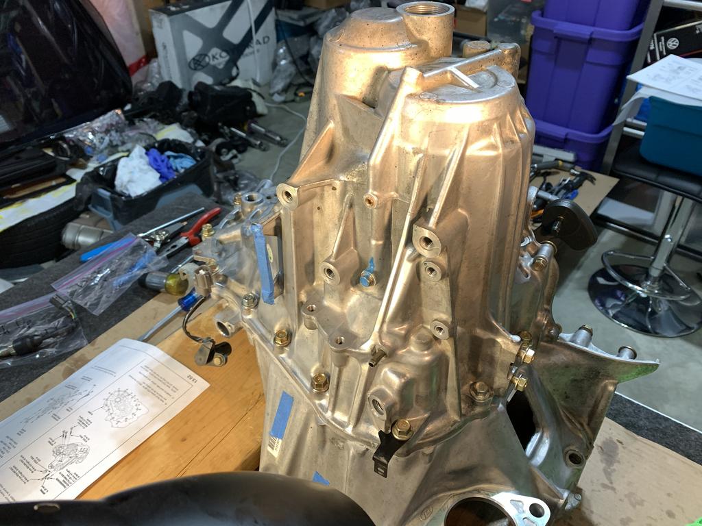
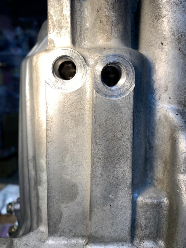
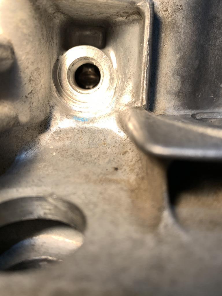
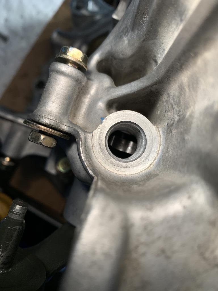
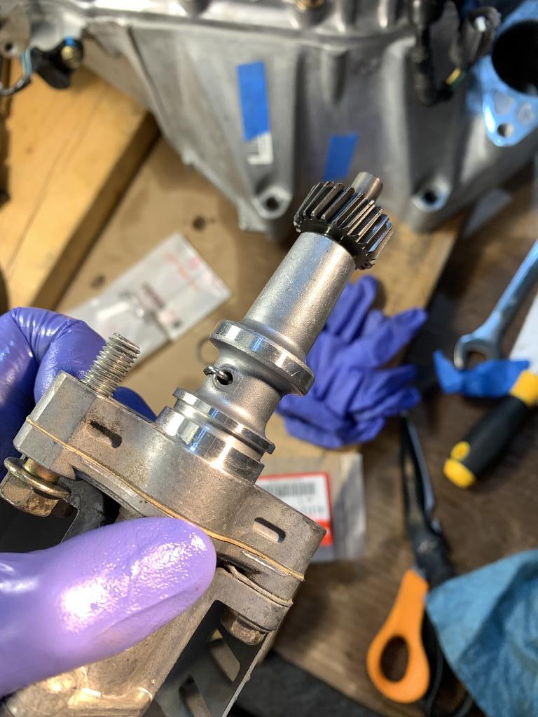
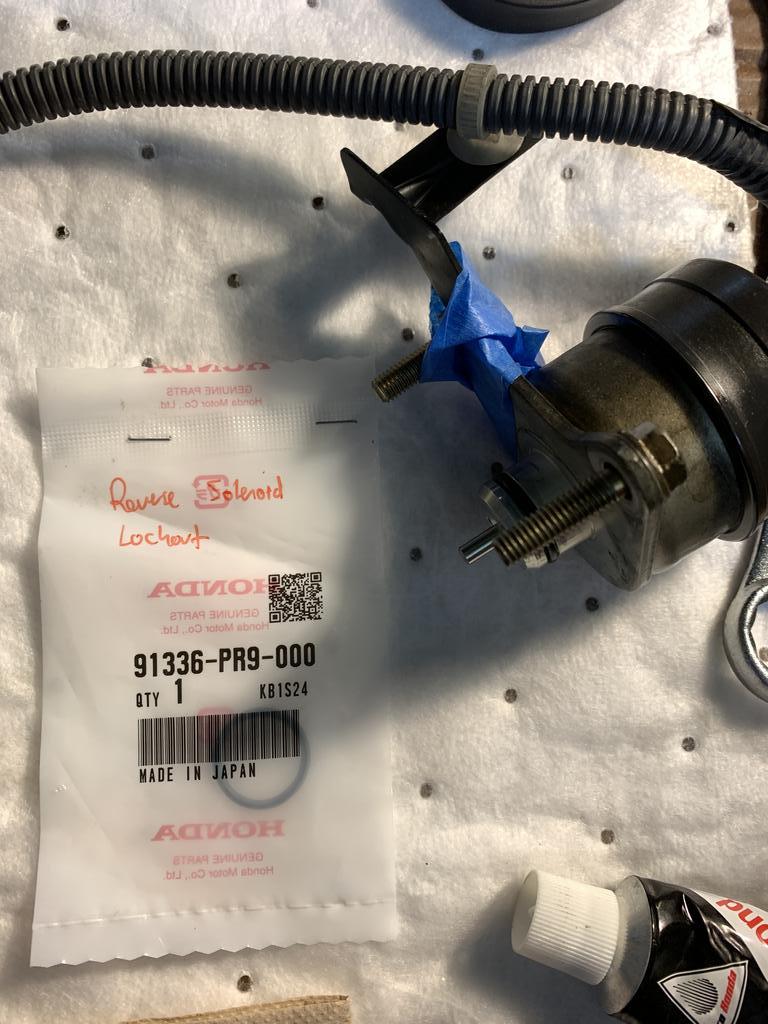
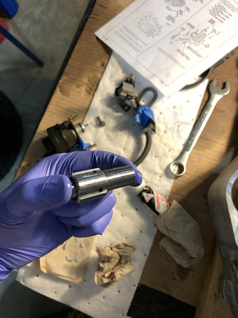
I chose to replace the spring that centers the shifter into the neutral position. All I can say is DO NOT do this if you don’t have to. That spring clip was a pain. Note the shift piece is backwards in the first photo. The second photo shows it correctly.
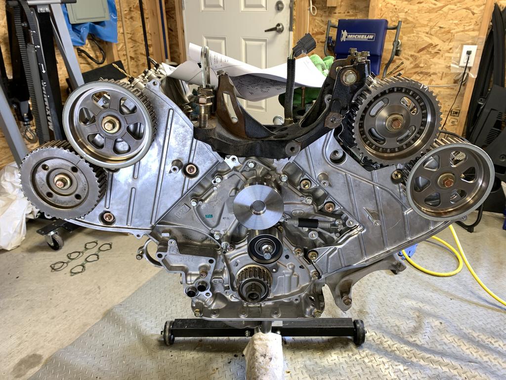
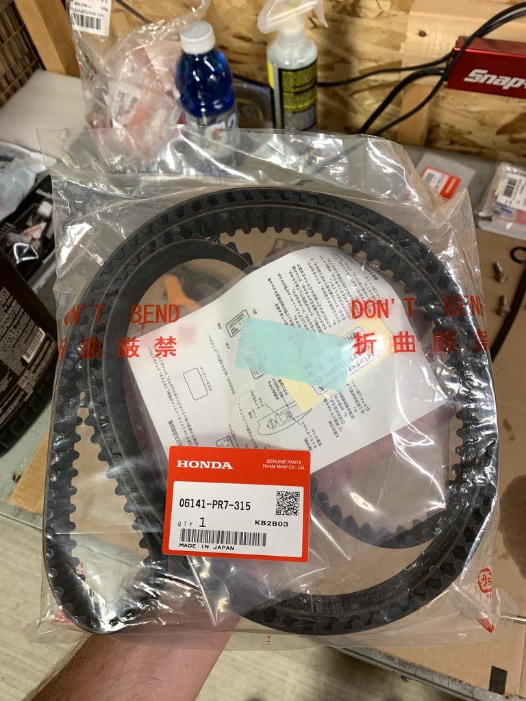
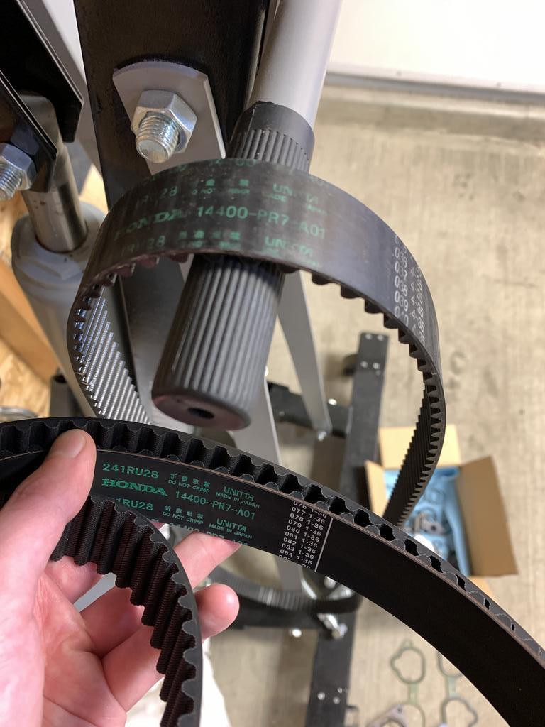
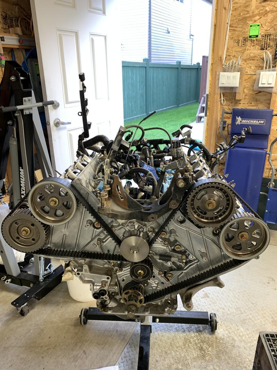
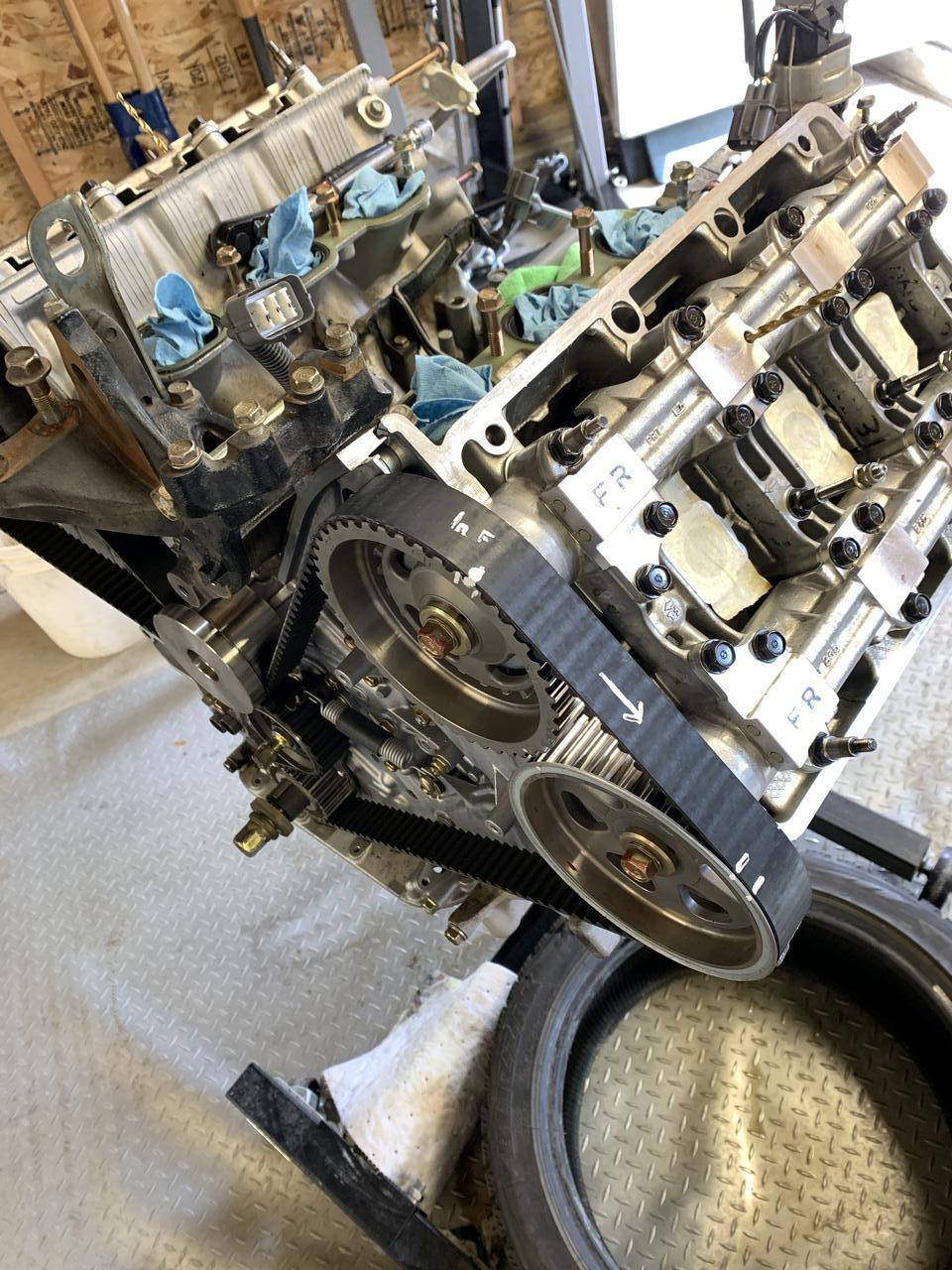
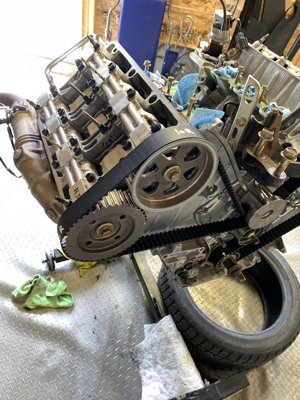
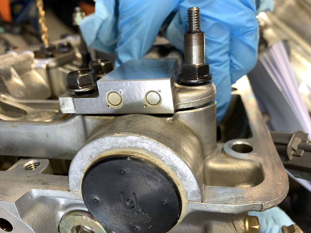
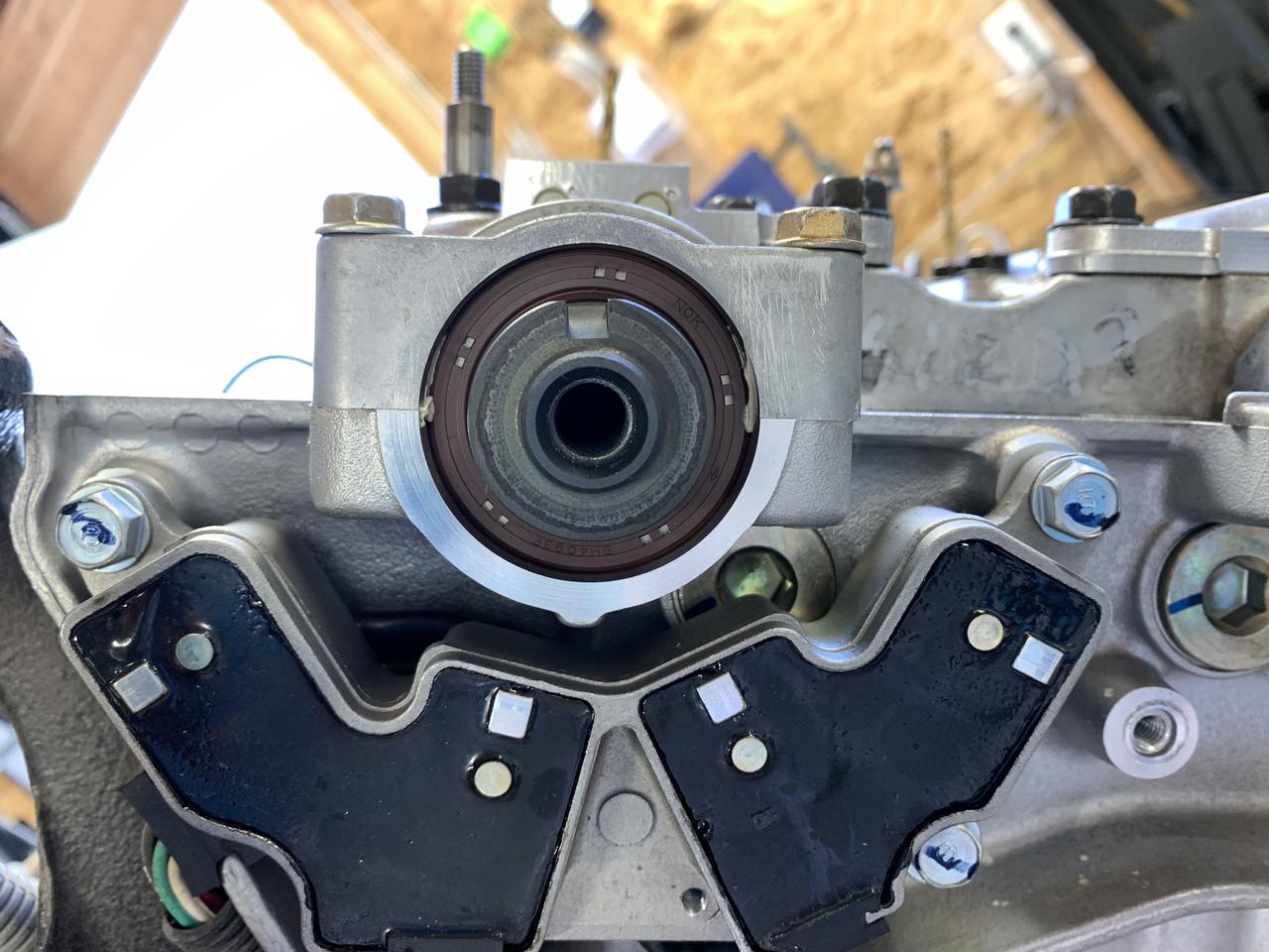
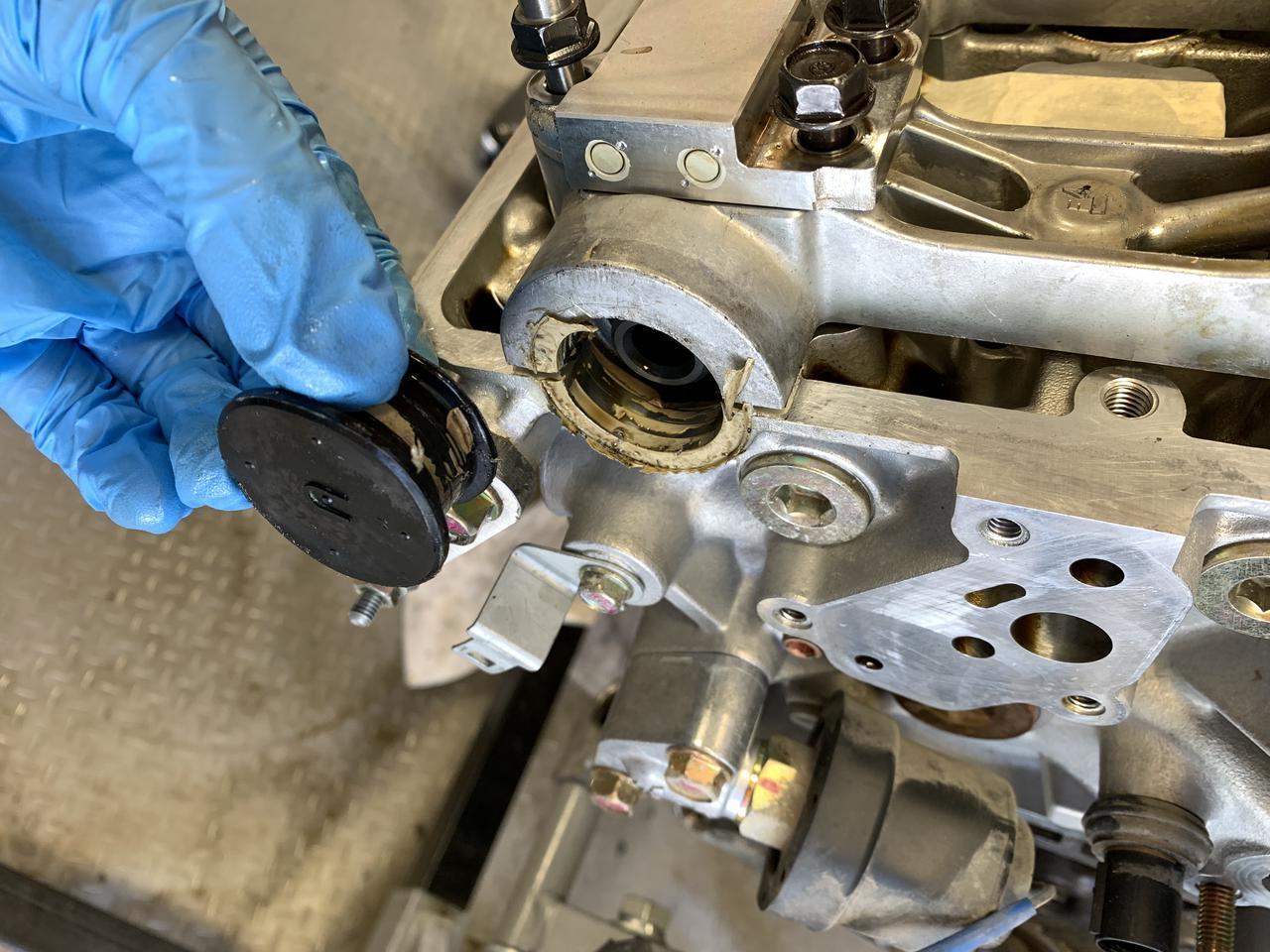
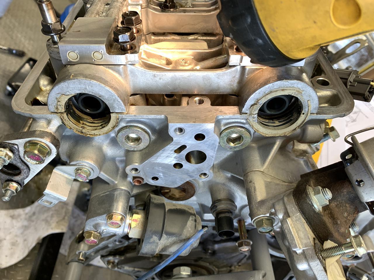
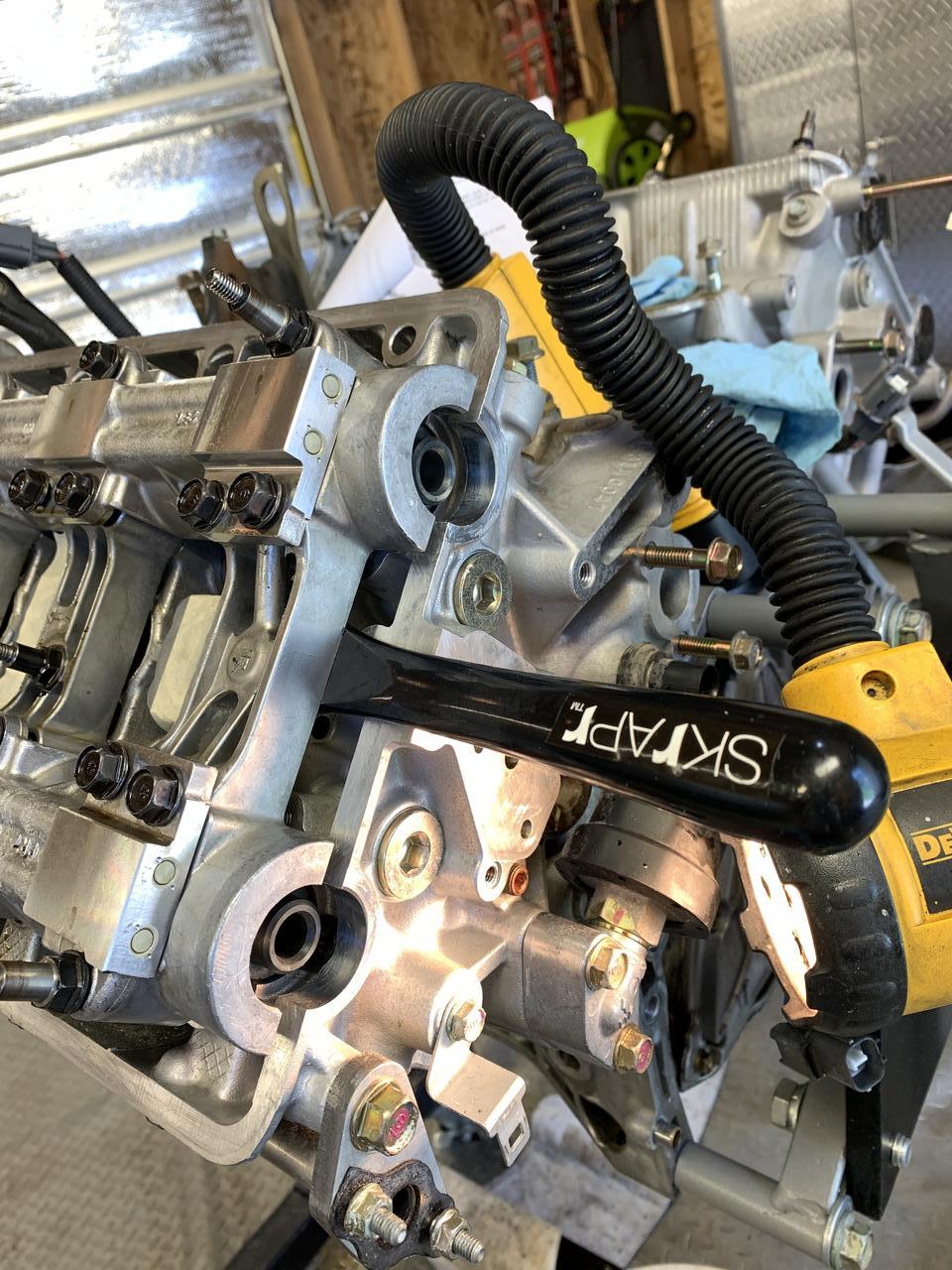
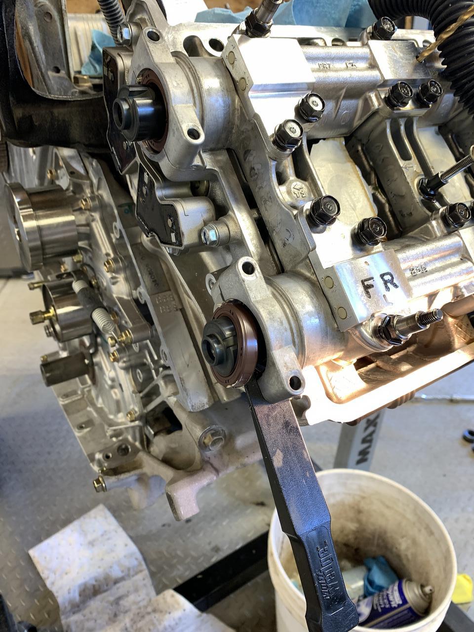
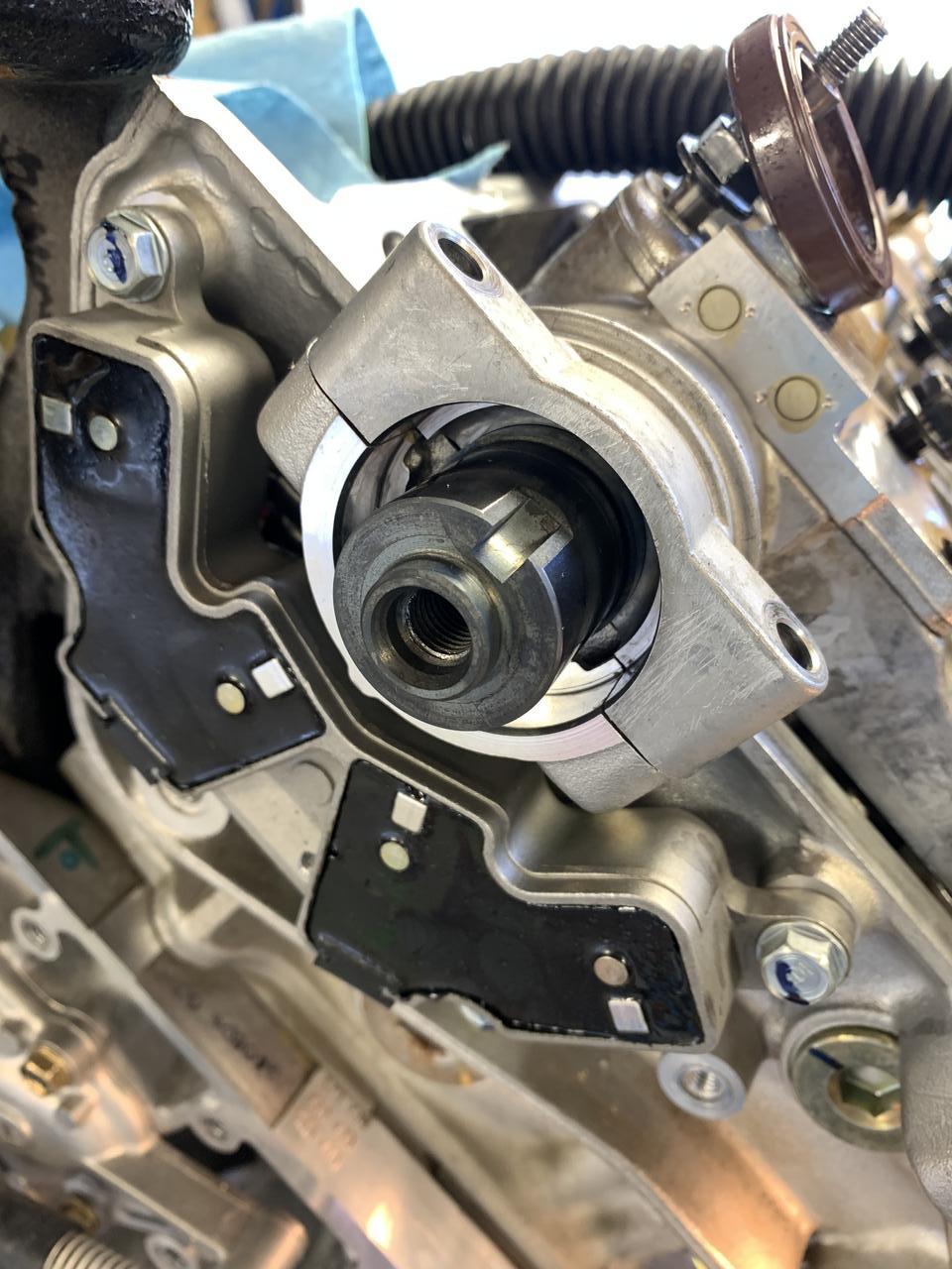
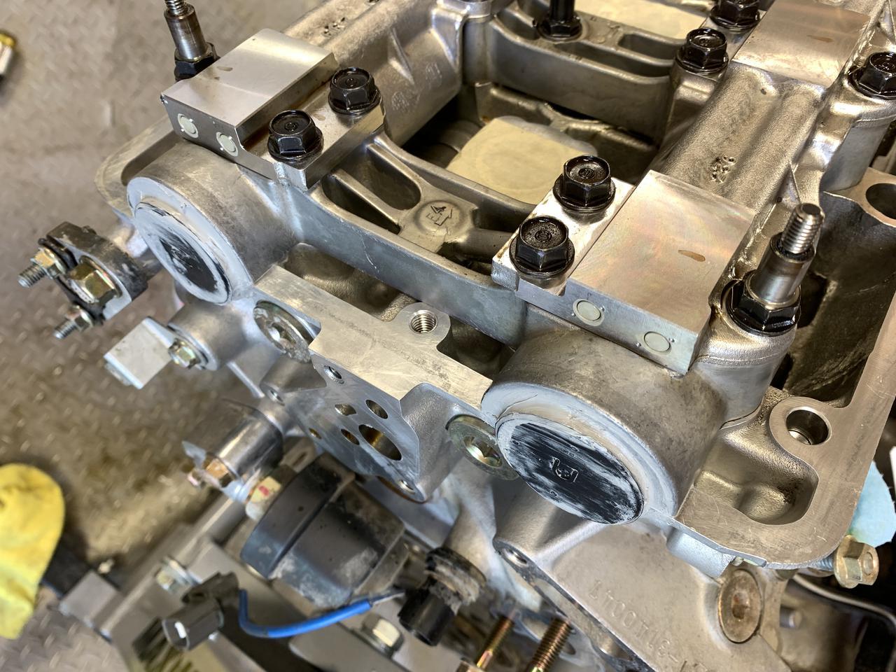
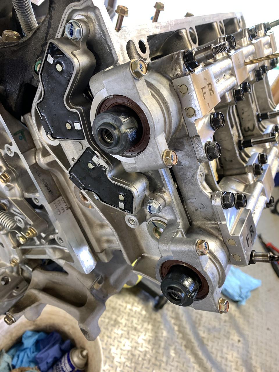
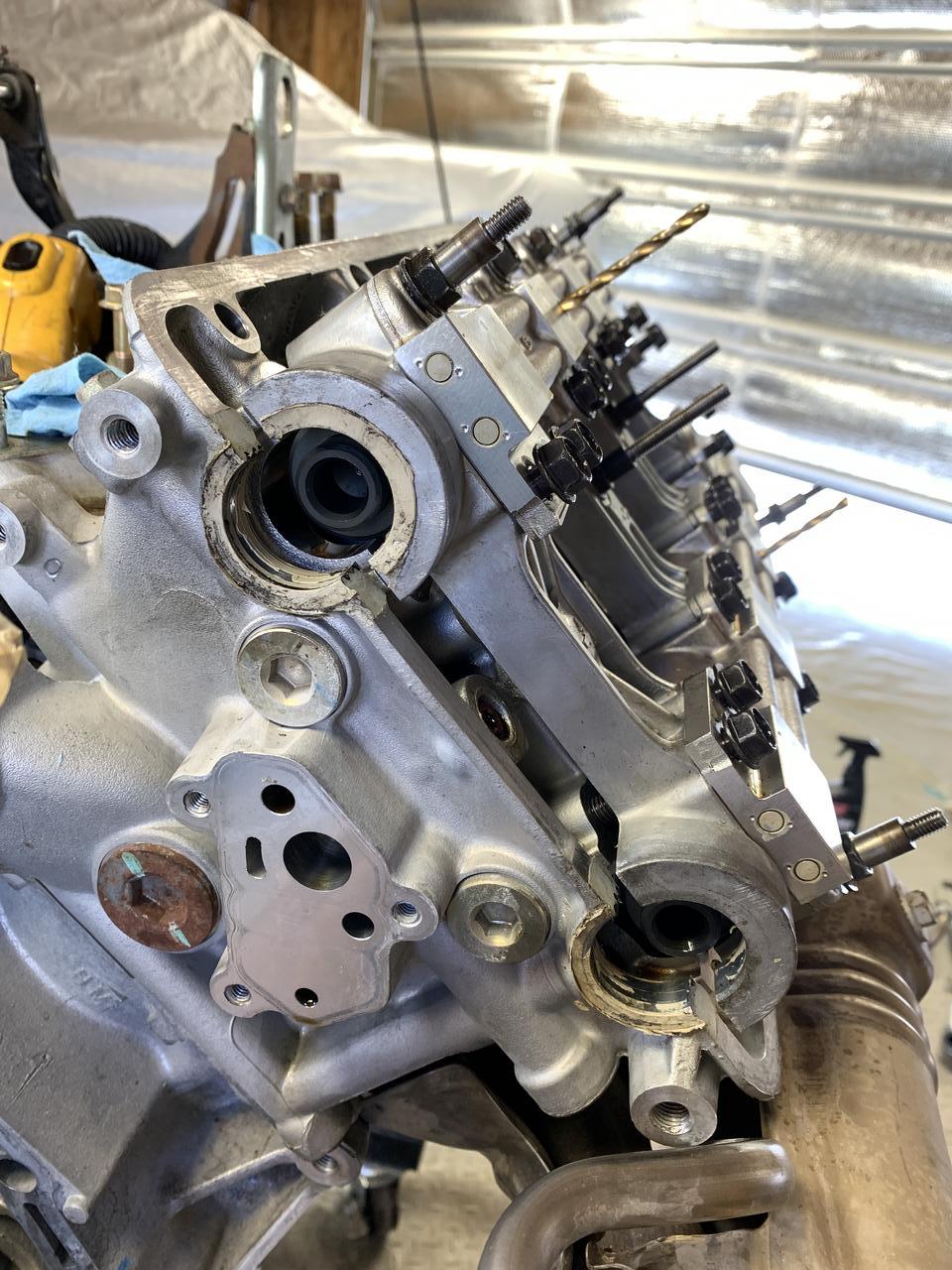
uIuRb8m.jpg


zYZO2D7.jpg


8Oi1Jk4.jpg
 
Then onto the reverse shaft assembly. This was a cake walk relatively speaking to the main and counter shafts.

itJW940.jpg


3QnQsh2.jpg


For me to get the reverse shaft in I had to move the gears into position and then lift the shaft up until they slid in. Then I lowered the shaft. Remember to line up your synchro hub as it has teeth that are deeper 120 degrees apart. You won’t be able to shift into reverse otherwise but everything will seem all good at the stage I have pictured below.

N5iDeY6.jpg


QYEhcJa.jpg


Then only the reverse lever is left and the tranny internals are done!

juPQskR.jpg


TNj8HEr.jpg
 
Now to start marrying the 2 halves together. I took my sweet time practicing how it goes together. The shift lever was a bit tricky but if you move it into position as you lower the case down it seems to work. The snap ring I was worried about too. I had to spread the ring with pliers as I lifted the counter shaft with a flat head. I’m not sure if the 6 speeds have stronger snap rings but there is no way you can lift it up with the snap ring putting pressure on (or at least way more force than I wanted to exert on the aluminum housing).

OvmFvoq.jpg


The picture below looks like it’s in position but it isn’t.
bvyzgbu.jpg


Now it’s in. Notice the gap between the open ends.
keVJaAG.jpg


After that take it all apart again and begin to clean it really really well. I used acetone. You use what you’re comfortable with.

2sWLXRU.jpg


Then get the Hondabond out and start the final home stretch. Be sure to get the 2 brackets ready that the tranny bolts hold. One of them is the reverse light switch and the other is the diff speed sensor bracket.

bcnQoix.jpg
 
Service manual says to put the goo on the tranny case side and do the circumference of each bolt hole. I’ve never worked with Hondabond before but it was a bit of a pain. I cut the funnel to a small bead and as I was squeezing the back end of the tube broke open. So I cut more of the funnel off but it was still hard to squeeze out. I ended up just making a mess out of everything and butchered the bead. There is probably way more on there than should be but meh…whatever. There was surprisingly not too much that splooged out. There is a relief built into the tranny case side so maybe that’s where the excess went.

uOxabY2.jpg


n3fChDo.jpg


fzNlN1l.jpg


I’m happy I tested the snap ring setting. This went very smoothly.

Fe0WLnx.jpg
 
With that the tranny is now together. Start on auxiliaries.

I bought new o-rings for everything
iw94m0b.jpg


cFvL50V.jpg


First up are the sealing detent bolts. I will say without these bolts the shifter mechanism feels very sloppy. I really didn’t think these did that much but it feels really really good with the 4 of these in. In the pictures below I’m trying to show the detents of the shift fork shafts in the holes.

uKjggb3.jpg


0XWwj0W.jpg


ahs4fXn.jpg


Manual says to put Hondabond on the threads
G5sXCGo.jpg


4X4aTIL.jpg
 
Diff speed o-ring
z7Xzbxi.jpg


Reverse lockout o-ring
SPnQlei.jpg


The actual piston that drives down and locks reverse out
iHsDasQ.jpg


And with that now installed the tranny is fully complete and dressed! I put the old oil filter back in for now as I’m only going to run the new fluid briefly before I change it out. At that point I’ll put the new strainer in.

Ready to go back to the garage. My wife will be happy when “this stupid thing is out of the basement” so she can have her laundry table back.

zGpDjIC.jpg


Vn5RcjC.jpg


m5nJeww.jpg
 
I don't think your math was wrong on the mainshaft clearance, the method listed in the service manual is just terrible. The best way I found to do the initial measurement was to bolt the case halves together with the mainshaft installed but no spring washer then measure the movement at the tip of the shaft pushing in and pulling out. Compounding errors with multiple feeler gauge measurements just can't give accurate results, that factory method is more to establish a base line from which to adjust the shims.

Edit: You inspired me to fabricate a tool to pull on the mainshaft and check it that way, and turns out I was way off. Without the washer I was measuring 0.0400" on the dot which seemed perfect, but with the spring washer and puller tool I was seeing 0.012" movement which is way above spec. (0.0055-0.0083" for 5spd)
 
Last edited:
[MENTION=33247]MotorMouth93[/MENTION] , glad you got yours sorted out and honestly great job on that "make shift" tool that looks actually pretty decent. I spent $150 on mine from a place and if I'd known I'd commission you to build 2 haha!
 
Does anyone know where part number 91318-PT0-003 is supposed to go? The diagram shows it as going behind the main water pump timing cover but I can't see where it goes. I also didn't see any o-ring come out unless it dropped out without me noticing (I have a story about the water pump dowels.....turns out they're in there quite loose and the new pump doesn't come with them).

The o-ring measures 10 mm ID by 13 mm OD.

Krv8eqp.jpg


The part is shown as #23 in the picture below.
dvTU70i.jpg


YB8msCv.jpg
 
That's for the original TB lower cover + original WP design.
The original design spec is no longer manufactured for both of them so the o-ring in question is not required.

Not sure what parts # you used for the WP but if you use 19200-PR7-305, it consists of 3 parts - latest design WP + latest design TB Lower cover + small grommet for the WP seeping tube.

In your photo, you already have the latest WP design.
Be careful using the drill bit as the cam locking pin.


Kaz
 
[MENTION=25737]Kaz-kzukNA1[/MENTION] , thank you! That helps immensely. Weird how the 2005 parts diagram still has that o-ring on there. But definitely better to know where it goes (or doesn't go) so I can strike it from my mental worries.

um....how did you know about the drill bit issue??? :) It's like you can see into my computer! The warning should be heeded by all. Case and point but thankfully I had the belt on. Side note putting in the new rear plugs and cam seals is a terrible job. If the engine was in the car there would be some foul language that's for sure.

Ju3QNOq.jpg


p7pCkKN.jpg


For the timing belt itself I did buy the kit with the new water pump cover in it (I ended up using my original 2005 cover though). The timing belt package is also a different part number but the belt itself is the same.

GHB6Q2b.jpg


1lNfQi5.jpg


o2EiA39.jpg


For my original 16-17 year old belt you can start to see the wear flat spots on the edges. That dull spot isn't "camera flash". I think there was some life in it still but doesn't hurt to change it.
wo3XPIh.jpg


mBurG1x.jpg


dWoidSV.jpg


For the original belt I was thinking of doing some sort of destructive test on it and measure the force it takes to break it. If someone can think of a way that will be useful to any future people I'm all ears. I don't think the belts actually snap but the teeth sheer off instead (from a failed pulley)...which then leads to the belt breaking.
 
[MENTION=25016]The King[/MENTION] , mileage is 23,476 miles at the last gas station before my house few minutes away and the belt had 16 years on it. 90% city driving and odd road trip here and there. At least once taken to the redline each drive. And I do truly mean that; there is a freeway near my house with a 100 speed limit so I pin 1st gear on the onramp then just ease it into 2nd and by then I'm right around the flow of traffic. I wouldn't say it's "hard" miles but just normal-ish use.

Warning alert to everyone to get your pitch forks and flame torches ready....if it wasn't for my tranny, I'd have run this belt for another 3-4 years. We don't really get dry rot here too much from my experience or at least no where near the hot climates. I would be curious to somehow do a destructive test on my original belt and see what force it takes to break it. Then repeat with a new one (but of course the $$$ is wasted).
 
For the engine side I’ve read stories on the forums that oil starvation and the intake butterfly screws are a problem. So figured I would address everything now while it’s all accessible.

Start off with pulling the oil pan and the intake manifold.

W5Q0jFS.jpg


Surprised face:
WAPfvHs.jpg


r9s48Fu.jpg


Intake manifold is a bit more involved.
iyEqkQP.jpg


qip1t7c.jpg


iMgpHUs.jpg
 
Deep down in the intake manifold you can see my flappers. Those screws are the problem.

pUpwDOc.jpg


UWBAFsm.jpg


Honda put some emissions stuff right in the way of the actuator. So have to take the air delivery pipes off. Earlier model cars don’t have this problem.
XFVU28I.jpg


Uy63fje.jpg


6xk4UkU.jpg


Flip the intake manifold over and start unbolting.
tXD91rr.jpg


kBplXMs.jpg
 
The later model cars have some sort of sensors missing here; these are factory welds.

qaUEmzV.jpg


S5nFXOt.jpg


My screws in particular were flared. I don’t see how these could come out but none-the-less; I’ll still comply and weld them up.

FW7o9jZ.jpg


I test fitted the baffle then scrapped off a few centimeters of paint above and below the baffle.

AeJx4vS.jpg


FY50qEC.jpg
 
Then go visit your friendly neighborhood welder. Note that apparently, I didn’t clean the area around the temperature sensor bung well enough and 1 spot blew through on him. I think I forgot the threads of the oil drain plug and some oil seeped out from the heat.

NkkADXV.jpg


68g05b4.jpg


CtNxkhW.jpg


jP3Omgk.jpg


EjRNkfV.jpg
 
He had an awesome original Willy’s Jeep that his dad owned from new. Still running and driving (but only around the farm).

0Xbpqyf.jpg


ake2eqo.jpg


uxgTEmf.jpg


He said it’s normally way easier to do work without somebody standing a foot away from him and taking pictures. I say that’s fair dinkham haha

T2MUPFR.jpg


JWJNEHd.jpg
 
I bet him $5 that instead of one of the screws backing out that the weld will flake off instead and work its way through my engine. Truthfully, I would say don’t bother doing this “fix”. It’s a bit of a faff and with the flared screws it seems unlikely to come out.

QS9oUMB.jpg


Head back to the garage and get cracking on the engine. Start with this:

VjCBcKz.jpg


End up with this a few minutes later:
XLetOQt.jpg
 
My belt looked okay but was shiny
uX77MnU.jpg


Eo4oZs1.jpg


I’m changing the valley pan pipe o-rings too. The guy from M539Restorations always does it …but on BMW’s.
42GyGdX.jpg


Bwnc3Jx.jpg


Vtec ports below
lQeiV8e.jpg
 
I always mark the belts themselves instead of relying on only the timing marks. Subaru belts for example already come pre-marked and I don’t understand why all of the manufacturers don’t do this. The marks can be anything you want. Here I just wrote Intake cam, front cylinder head.

7RgMV0G.jpg


A7Io1Nd.jpg


While I was in there any reasonable person would do the crank seals and caps right??? Holy fook me I wouldn’t have done them if I understood what a pain these would be. Honda glued/sealed them in for the later model years. All of the pictures below are how it came from Honda, this engine was never pulled apart before. They used a tube of Hondabond on the rear plugs! You also have to unbolt all of the cam bolts and lift the holders by ~1.5 centimeters which is a bit unnerving since the timing belt isn’t installed at this stage. I left the drill bits in as cam holders but I’m not sure if I was supposed to since one of the drill bits came out bent.

Eaop07N.jpg


Ju3QNOq.jpg


p7pCkKN.jpg
 
I’ve never seen cam seals with RTV on them before from factory
fZO1HOj.jpg


v3nM2a9.jpg


Once again what you see below is how it came from Honda. Note I’m secretly a “more is better” kind of guy. I don’t mind a bit of extra sealant splooging out and I don’t quite understand why people lose their minds over it.

QCEraIG.jpg


Now came the part that pictures can’t tell. The amount of time this took to clean was hours. I can’t see a shop sitting down and doing this especially if the engine is in the car. I took the plastic scraper and got every last bit of sealant off. Then acetone’d it and got it clean. In the car this would be a nightmare as you’d have to use mirrors and be bent over the quarter panel. If your plugs aren’t leaking then do not touch them would be my recommendation.

HTkETdc.jpg


KXnUXcN.jpg


JC4XmRg.jpg
 
I did attempt to make it look good but failed hard. The Hondabond is sticky and I accidentally touched the black plug. I then tried to wipe it off (with my said sticky finger) and made it worse. It looks nasty but it’s not far off from the same quantity that Honda used (at least for the sealing portion).

CNHxRuc.jpg


The cam seals went a touch better.
MwvL8ui.jpg


Then rinse and repeat on the other side. Note that the intake cam on the rear bank is in tension so it was trying to lift up the entire time. Very unnerving.

The below picture is how Honda had it
LYgGm0L.jpg


Be honest..for the cam plugs can you tell I did far left, 2nd from far left, far right, then second from far right in that order???? �� An experienced shop better do a nicer job than the 4th one haha.

Cf8wu87.jpg
 
Back
Top