

Whats the shop in Texas? A localish suspension guru would be good to know about.
-
Protip: Profile posts are public! Use Conversations to message other members privately. Everyone can see the content of a profile post.
You are using an out of date browser. It may not display this or other websites correctly.
You should upgrade or use an alternative browser.
You should upgrade or use an alternative browser.
bogle's 1991 mild build thread
- Thread starter bogle
- Start date
Curious what your thoughts are on the coilovers you want to go with? I ended up with used JRZ I got a good deal on and got rebuilt, but I know what I would pick now. I can talk for hours on suspension and engines haha. I have a friend that owns a high end suspension shop back in TX where I moved from. He has an in house shock dyno and has tried tonsssss of shocks, so great to pick his brain. Where are you at in California? I just moved to Reno from TX, so not too far from Northern CA.
I ended up deciding on an MCS 1WNR setup, but it will be a ways out before I get them. What would you pick now over the JRZ? I’m sure the JRZ setup is super nice.
I’m in Sonoma county near Santa Rosa. If you’ll ever be in the area, definitely let me know. A lot of great driving roads around here and around the Bay Area in general.
- Joined
- 22 November 2014
- Messages
- 77
The shop is called Inertia Lab, Chris is the owner. Great guy.Whats the shop in Texas? A localish suspension guru would be good to know about.
Oh man the MCS are very nice, great pick. Terry over at Vorshlag uses them all the time, another friend of mine. So after picking Chris's brain for a long time, it would be Nitron. They arent that popular here except on motorcycles, but they are very popular in Europe. However their pricing is actually really good, about on par with Ohlins R&T or KW V3 I would say, sometimes even less. However according to him they are really as good as MCS or Moton or AST but for less money. The 1WNR are close in price, but the Nitron are slightly cheaper and on strut cars come with camber plates included. I want to put them on something really bad to try them out! But I just got the JRZ for the NSX and got Ohlins R&T for the E90 M3 wagon before I had talked to him.I ended up deciding on an MCS 1WNR setup, but it will be a ways out before I get them. What would you pick now over the JRZ? I’m sure the JRZ setup is super nice. I’m in Sonoma county near Santa Rosa. If you’ll ever be in the area, definitely let me know. A lot of great driving roads around here and around the Bay Area in general.
Interesting, I’ve never heard of Nitron! Looks like there is an off the shelf nsx kit with integrated remote reservoirs, it’s 2k+ more than the MCS 1WNR (on par with their 2WR). But I’m sure he can do a totally custom thing like with the MCS.
I just went with the AR motorsports “go to” MCS/swift setup which was similar damping curves to the NA1 NSX-R. Sounded like they’ve done a number of cars with this setup and all rave reviews. We’ll see in like 6 weeks…
I just went with the AR motorsports “go to” MCS/swift setup which was similar damping curves to the NA1 NSX-R. Sounded like they’ve done a number of cars with this setup and all rave reviews. We’ll see in like 6 weeks…
- Joined
- 22 November 2014
- Messages
- 77
Yah from talking to Chris there is a 2WNR version you can buy from them no problem. Also, I dont know where you were seeing prices, but he said the few guys who do list in the US have very high prices. He said true retail from Nitron is usually quite a bit cheaper then what the few US resellers list. But ya your setup is going to be awesome, no doubt about it! Curious to see what you think.
Good to know on the price on the Nitrons. I just did a quick search on the internet, there is a part number for an off the shelf NSX kit from them, and everywhere it was in the 6k ish range. But these were def random websites. I’m sure a more direct route is significantly cheaper.
On the MCS 2WNR side, the internet consensus on all the forums I looked at (here, Porsche, bmw) was to either go 1WNR or 2WR. Something about how it’s tough to build both adjustments into the shock body, so they are sort of a compromised design. Not really sure how that translates into performance, usability, or longevity. I probably should have asked AR when I talked to him. In any case, the internet lore made the choice a little easier. Part of me reaaally wanted to do the 2WR, but the extra cost and complexity in mounting the reservoirs didn’t seem worth it for my 99% street use.
On the MCS 2WNR side, the internet consensus on all the forums I looked at (here, Porsche, bmw) was to either go 1WNR or 2WR. Something about how it’s tough to build both adjustments into the shock body, so they are sort of a compromised design. Not really sure how that translates into performance, usability, or longevity. I probably should have asked AR when I talked to him. In any case, the internet lore made the choice a little easier. Part of me reaaally wanted to do the 2WR, but the extra cost and complexity in mounting the reservoirs didn’t seem worth it for my 99% street use.
- Joined
- 22 November 2014
- Messages
- 77
Yes I would agree, I think you made the good choice! What rates did you go with?
I went with 9k front 7k rear. So in between the 92 R’s 8/6 and the later R’s 10/8 rates. I figured it would give me a good stating point. If I feel things are too stiff, I can go to 8k/6k, or if too soft, I can move up. I told him I wanted to be able to experiment with spring rates and he said they are valved such that they can easily handle that range.
I also read (both about the MCS dampers and swift springs) that even with higher rates the ride quality is still really great. We will see, def can’t wait.
I also read (both about the MCS dampers and swift springs) that even with higher rates the ride quality is still really great. We will see, def can’t wait.
ABS upgrade overview
The ABS job is in the bag, the car has been upgraded to a 2000+ ABS unit. I am so happy to be able to say that!
The brakes feel fantastic. Pedal feel before the work was a little spongy. No more! I replaced a number of things in this pass: ABS, MC, brake lines to the calipers, and obviously a full fluid flush. The brake pedal is now just below the gas when super hard on the brakes, making it easier to heel-toe. It'd sink pretty low when really on them prior. I actually bled them again hot after the initial drive and managed to get a decent amount of little bubbles out of the rears, maybe they'll be better still?!
The ABS itself feels a lot more subtle than I was expecting. Hard to describe, but it feels quite fast-acting, both to kick on and to stop, with nice, light feedback. I had low expectations TBH. I figured it'd be slightly better than my old DA Integra which had crazy pedal vibration, it would push the pedal back at you like an inch, and once on, it'd run for a couple seconds minimum. Happy to report that this new one is miles better.
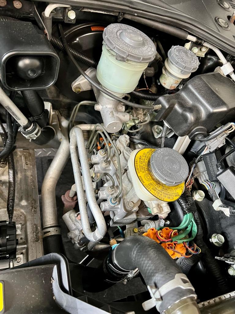
Before
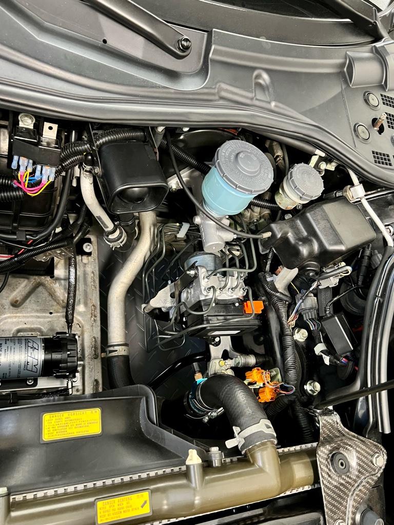
After
Work, work, work, work, work
The ABS did not work when I bought the car. I've had the new parts for a few months, but I have not been looking forward to doing the work. Mostly because of the time commitment, but also because it was likely to be super gooey. If only I could work on the car and not get dirty...
I considered taking all the parts somewhere and having it done so as not to burn a weekend. Though, all the shops I would trust with this are 2-3 hours away, which means 8-12 hours of driving all in. Might as well spend that time doing it myself, eh?
The job was very time consuming, likely the biggest job I’ve done on the car in one go. It took me 2.75 full days working like 9-6. Definitely a lot more time than I negotiated with the girl, and about half way through I was in the doghouse. She's over it now tho!
There was nothing nightmarishly hard, just 4,278 steps. I mostly followed warrenw’s guide, with supplemental docs from the MITA kit, and JP language docs from the KSP harness. I had to email Mita to get them to give me the English instructions for the kit, the good news is that English instructions do exist.
I’ll go into each day in more detail, but this post is kind of the tl;dr.
Hardest things in order
* Routing the FR and FL hard lines.
* Bleeding the MC and getting it in the car with minimal mess.
* Getting the blower motor out: I needed to remove the WMI tank. Then once the blower bolts were out, still didn’t want to come out.
* The harness required some problem solving and modification.
* OMFG so many steps.
Special tools
Beyond the standard 10/12/14/17 fare, I picked up a couple special tools.
* 10mm flare nut wrench
* 10mm crows foot socket which I used a lot more than expected
* Square socket for old ABS unit PN: 07HAA-SG00100 (I relieved ABS pressure out of the car)
* Oil spill mats; I love these things
* Crimper for the ABS power connector and jumper wire
* Speedbleeder bleeder bag + hose, very helpful
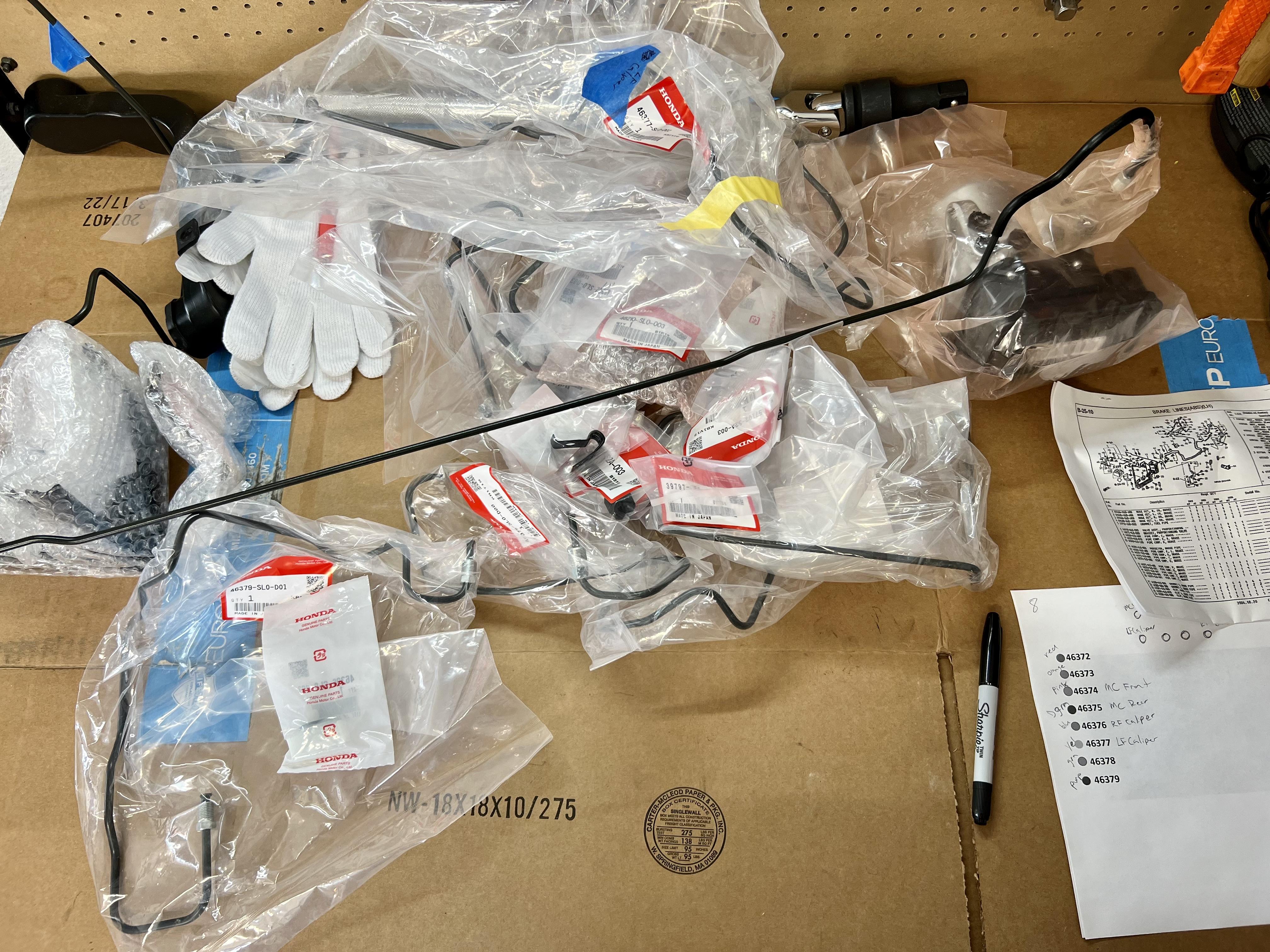
Parts
In addition to the ABS unit and alllll the hard lines, I also replaced the master cylinder, brake lines to the calipers, and some hardware
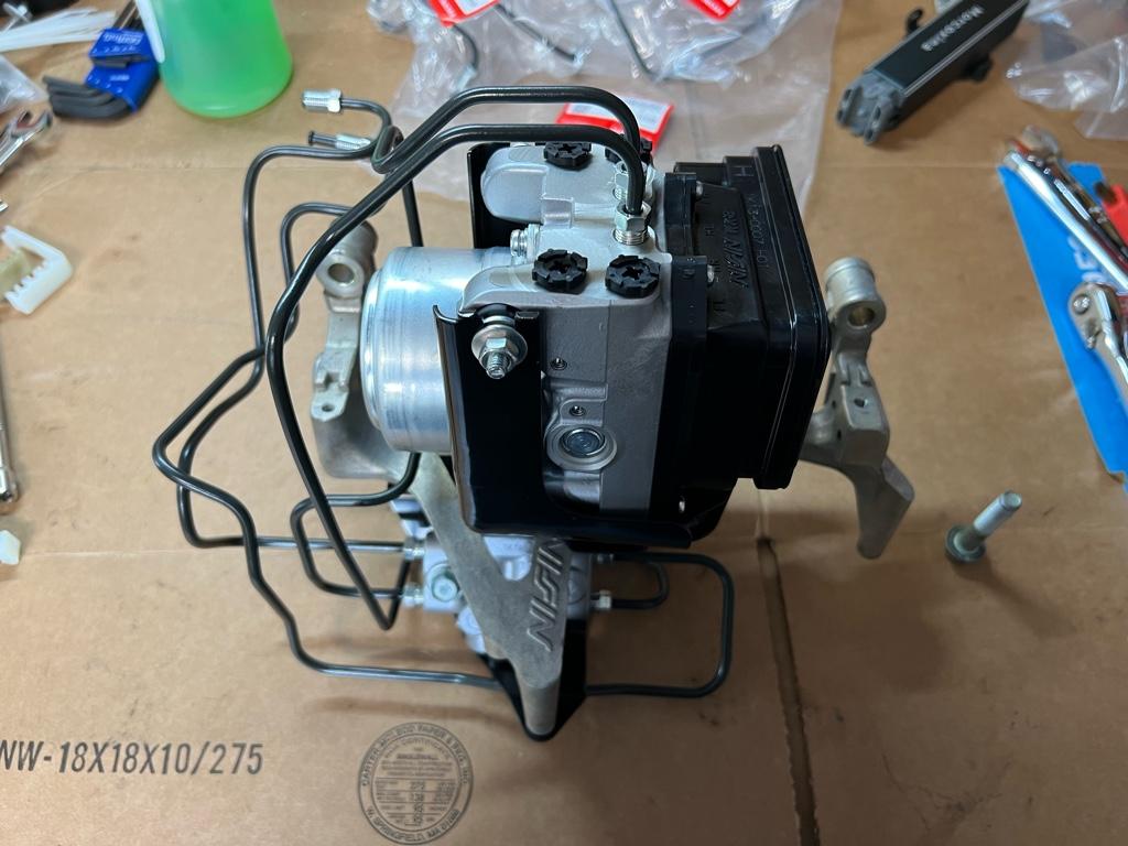
* MITA 00+ ABS upgrade kit with normal-guy, non-expert, non-R 00+ modulator. The kit came with the KSP harness and hard lines from the modulator to the front wheel wells.
* Male 2 pin Yazaki 58 Connector X Type for ABS power
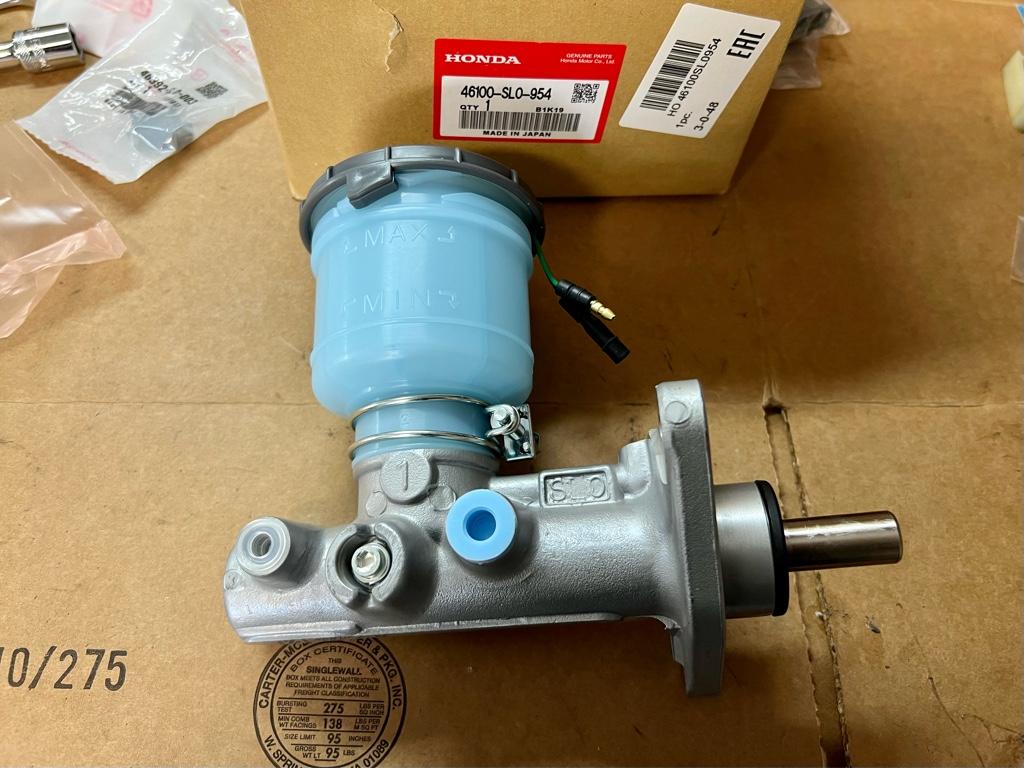
* Master cylinder PN: 46100-SL0-954
* Master cylinder nuts (PN: 94001-080-800S) and washers (PN: 94111-08800)
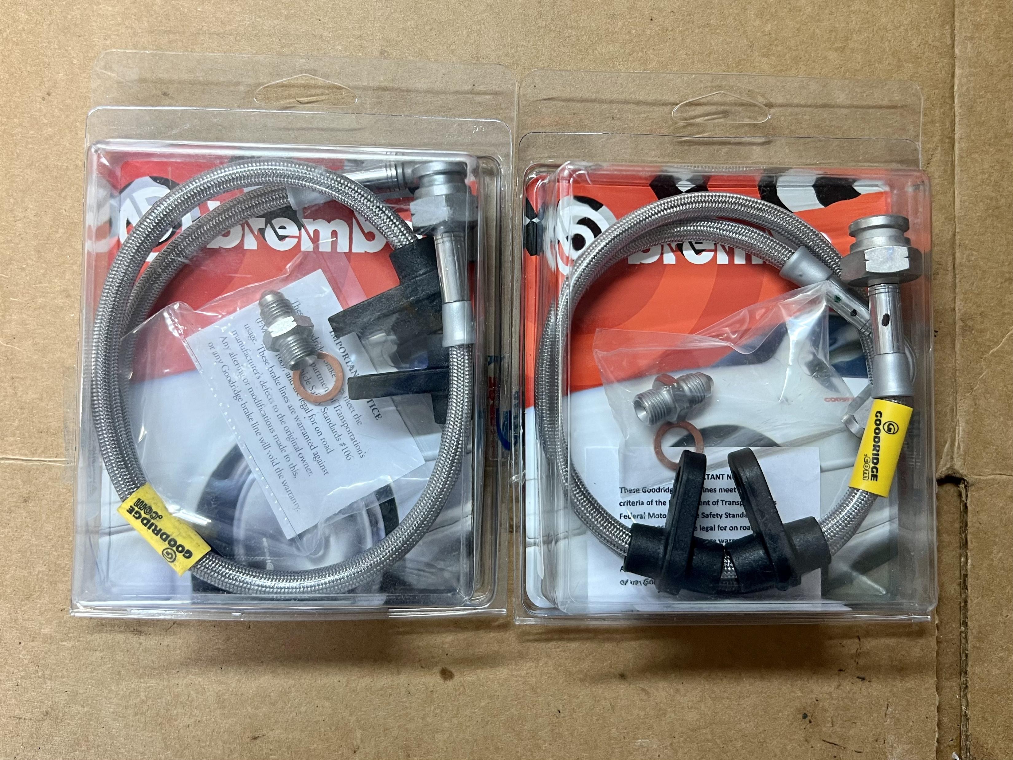
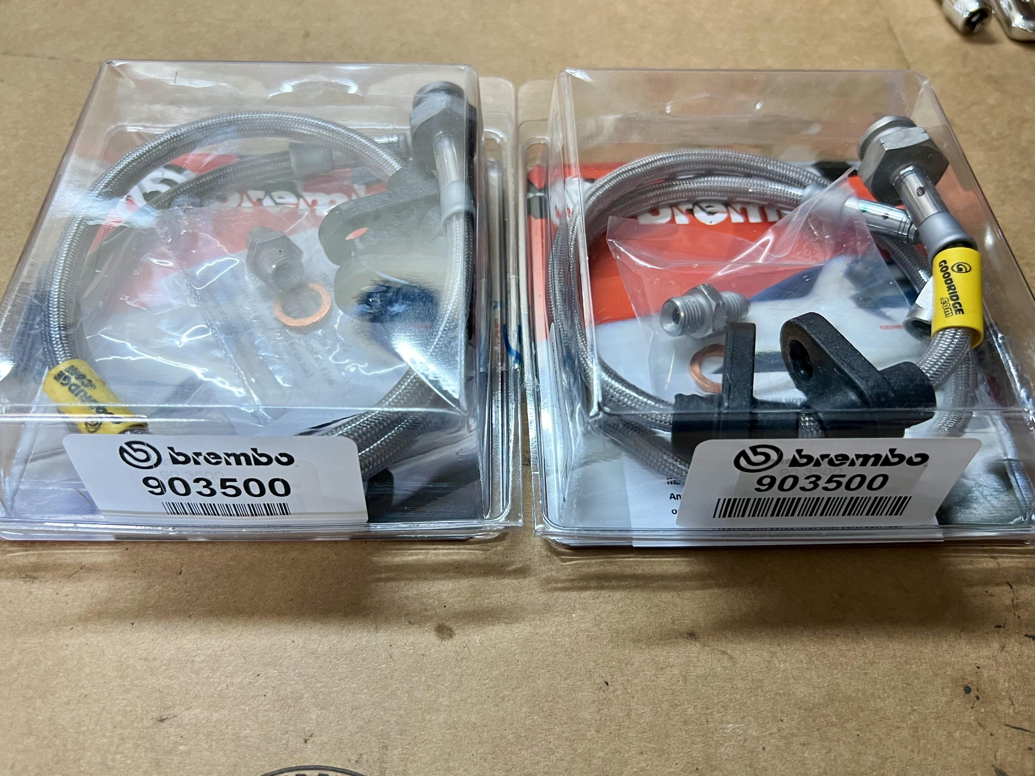
* Goodridge stainless lines (rear) PN: 20091
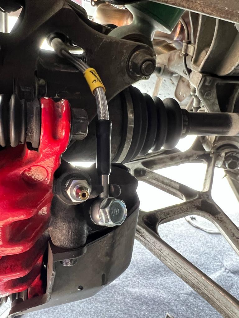
* Goodridge / Brembo stainless lines for Brembo GT BBK (front) PN: 903500
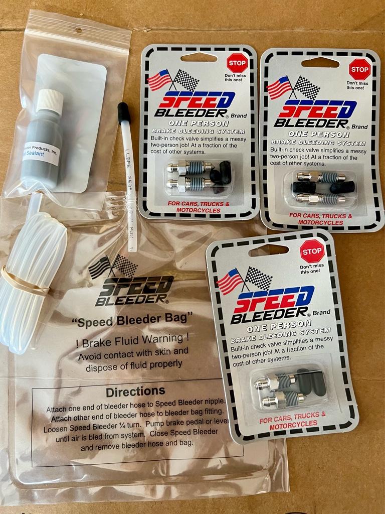
* 2x Speedbleeders M10x1.25 (for stock calipers PN: SB10125-SS / H9421)
* 2x Speedbleeders M10x1 (for Brembo calipers PN: SB1010S-SS / H9407 / H9497-2)
* 2x New Honda banjo bolts PN: 46462-SE0-000
* 4x New Honda crush washers PN: 46472-568-000
* HVAC Foam. I got 3/8" x 3/16", but stock foam is closer to 1/2" x 1/4"
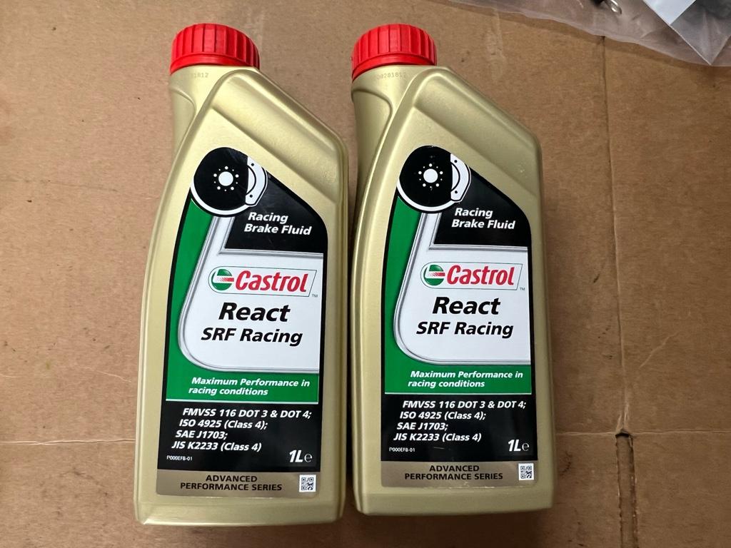
* 2 liters of brake fluid. 1.5L would have been enough, but I went with Castrol SRF and they don't sell 0.5L containers of it.
I went with the Mita 2000+ kit basically for ease of use, minimal fight. I know the S2k modulator setup is cheaper, but I didn't want to source anything extra. There were enough unknowns for me on this project, I just wanted it to be as easy as I could make it. I considered paying extra for the SoS kit just cause I knew they would have legit full instructions, but decided all the forum threads on the subject would be sufficient.

The Mita 2000+ kit also comes with new lines from the modulator to the wheel wells (pipe X: left; pipe Y: right), which the S2000 kit does not. No bending of the old lines!
Why the non-R modulator? I'm sure everyone reading this knows the R modulator is best with the R MC, which requires a new booster _and_ replacing one of the flare nuts. Also the R modulator programming is apparently setup for "pro" drivers, of which I am not.
The MC is new as I was unsure of the state of my current MC. They all end up leaking anyway, eh? The slightly spongy brakes indicated that I should probably replace it. Shooting for that new car feel, you know?
I'm replacing the brake lines to the calipers on all four corners cause it feels right while I'm in there. The existing fronts are of unknown age probably from the BBK upgrade. The rears are stock. It seemed like the Goodridge lines were the move over new OE lines as you get the benefits of an SS line with reliability. I have been afraid of SS lines in the past as they are hard to keep clean and inspect. I know some people here have had issues with SS lines failing. These are coated with some sheath to keep the gnar out. Maybe I'll replace them every couple years anyway as they are cheap.
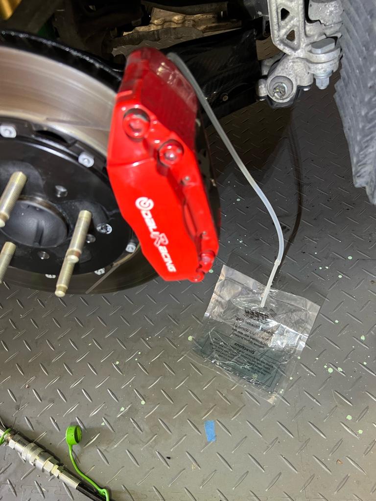
Here's the BBK units only cause I didn't take a pic of the rears before installing them:
Speed bleeders cause they are easy to use. I had to get two different thread pitches because of the BBK. I also bought their bleeder bag (huge help, no mess), a tube of sealant, and clutch-sized (M8) speed bleeders for the future.
PS: Sorry for some huge pics. Tapatalk is totally blowing it uploading today
The ABS job is in the bag, the car has been upgraded to a 2000+ ABS unit. I am so happy to be able to say that!
The brakes feel fantastic. Pedal feel before the work was a little spongy. No more! I replaced a number of things in this pass: ABS, MC, brake lines to the calipers, and obviously a full fluid flush. The brake pedal is now just below the gas when super hard on the brakes, making it easier to heel-toe. It'd sink pretty low when really on them prior. I actually bled them again hot after the initial drive and managed to get a decent amount of little bubbles out of the rears, maybe they'll be better still?!
The ABS itself feels a lot more subtle than I was expecting. Hard to describe, but it feels quite fast-acting, both to kick on and to stop, with nice, light feedback. I had low expectations TBH. I figured it'd be slightly better than my old DA Integra which had crazy pedal vibration, it would push the pedal back at you like an inch, and once on, it'd run for a couple seconds minimum. Happy to report that this new one is miles better.
Before
After
Work, work, work, work, work
The ABS did not work when I bought the car. I've had the new parts for a few months, but I have not been looking forward to doing the work. Mostly because of the time commitment, but also because it was likely to be super gooey. If only I could work on the car and not get dirty...
I considered taking all the parts somewhere and having it done so as not to burn a weekend. Though, all the shops I would trust with this are 2-3 hours away, which means 8-12 hours of driving all in. Might as well spend that time doing it myself, eh?
The job was very time consuming, likely the biggest job I’ve done on the car in one go. It took me 2.75 full days working like 9-6. Definitely a lot more time than I negotiated with the girl, and about half way through I was in the doghouse. She's over it now tho!
There was nothing nightmarishly hard, just 4,278 steps. I mostly followed warrenw’s guide, with supplemental docs from the MITA kit, and JP language docs from the KSP harness. I had to email Mita to get them to give me the English instructions for the kit, the good news is that English instructions do exist.
I’ll go into each day in more detail, but this post is kind of the tl;dr.
Hardest things in order
* Routing the FR and FL hard lines.
* Bleeding the MC and getting it in the car with minimal mess.
* Getting the blower motor out: I needed to remove the WMI tank. Then once the blower bolts were out, still didn’t want to come out.
* The harness required some problem solving and modification.
* OMFG so many steps.
Special tools
Beyond the standard 10/12/14/17 fare, I picked up a couple special tools.
* 10mm flare nut wrench
* 10mm crows foot socket which I used a lot more than expected
* Square socket for old ABS unit PN: 07HAA-SG00100 (I relieved ABS pressure out of the car)
* Oil spill mats; I love these things
* Crimper for the ABS power connector and jumper wire
* Speedbleeder bleeder bag + hose, very helpful
Parts
In addition to the ABS unit and alllll the hard lines, I also replaced the master cylinder, brake lines to the calipers, and some hardware
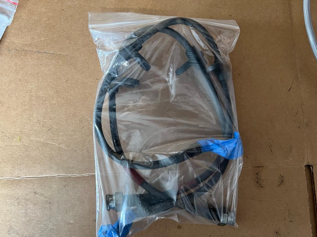
* MITA 00+ ABS upgrade kit with normal-guy, non-expert, non-R 00+ modulator. The kit came with the KSP harness and hard lines from the modulator to the front wheel wells.
* Male 2 pin Yazaki 58 Connector X Type for ABS power
* Master cylinder PN: 46100-SL0-954
* Master cylinder nuts (PN: 94001-080-800S) and washers (PN: 94111-08800)
* Goodridge stainless lines (rear) PN: 20091
* Goodridge / Brembo stainless lines for Brembo GT BBK (front) PN: 903500
* 2x Speedbleeders M10x1.25 (for stock calipers PN: SB10125-SS / H9421)
* 2x Speedbleeders M10x1 (for Brembo calipers PN: SB1010S-SS / H9407 / H9497-2)
* 2x New Honda banjo bolts PN: 46462-SE0-000
* 4x New Honda crush washers PN: 46472-568-000
* HVAC Foam. I got 3/8" x 3/16", but stock foam is closer to 1/2" x 1/4"
* 2 liters of brake fluid. 1.5L would have been enough, but I went with Castrol SRF and they don't sell 0.5L containers of it.
I went with the Mita 2000+ kit basically for ease of use, minimal fight. I know the S2k modulator setup is cheaper, but I didn't want to source anything extra. There were enough unknowns for me on this project, I just wanted it to be as easy as I could make it. I considered paying extra for the SoS kit just cause I knew they would have legit full instructions, but decided all the forum threads on the subject would be sufficient.
The Mita 2000+ kit also comes with new lines from the modulator to the wheel wells (pipe X: left; pipe Y: right), which the S2000 kit does not. No bending of the old lines!
Why the non-R modulator? I'm sure everyone reading this knows the R modulator is best with the R MC, which requires a new booster _and_ replacing one of the flare nuts. Also the R modulator programming is apparently setup for "pro" drivers, of which I am not.
The MC is new as I was unsure of the state of my current MC. They all end up leaking anyway, eh? The slightly spongy brakes indicated that I should probably replace it. Shooting for that new car feel, you know?
I'm replacing the brake lines to the calipers on all four corners cause it feels right while I'm in there. The existing fronts are of unknown age probably from the BBK upgrade. The rears are stock. It seemed like the Goodridge lines were the move over new OE lines as you get the benefits of an SS line with reliability. I have been afraid of SS lines in the past as they are hard to keep clean and inspect. I know some people here have had issues with SS lines failing. These are coated with some sheath to keep the gnar out. Maybe I'll replace them every couple years anyway as they are cheap.
Here's the BBK units only cause I didn't take a pic of the rears before installing them:
Speed bleeders cause they are easy to use. I had to get two different thread pitches because of the BBK. I also bought their bleeder bag (huge help, no mess), a tube of sealant, and clutch-sized (M8) speed bleeders for the future.
PS: Sorry for some huge pics. Tapatalk is totally blowing it uploading today
ABS Day 1: Removal
Day 1 was removal day. I got everything out of the car and managed to do a little cleaning.
The steps:
* Remove glovebox
* Remove ABS computer: not as bad as I was expecting
* Remove battery: mine is small, but still in the way
* Remove WMI tank
* Remove blower motor
* Unbolt cruise box at the bottom bracket, lay on cowl
* Turkey baster all the fluid I could
* Drain brakes fluid at the front calipers
* Remove front brake lines
* Remove old master cylinder
* Remove old ABS unit
* Remove old front wheel hard lines, I bent the F out of them to get them out
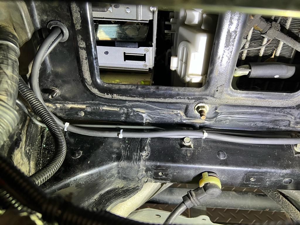
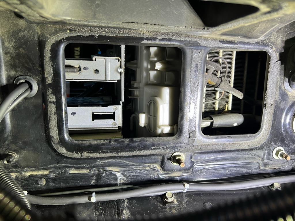
* Clean the chassis behind the abs and blower motor
* Assess harness situation, where should it go?
I didn't take a ton of removal photos, but a couple
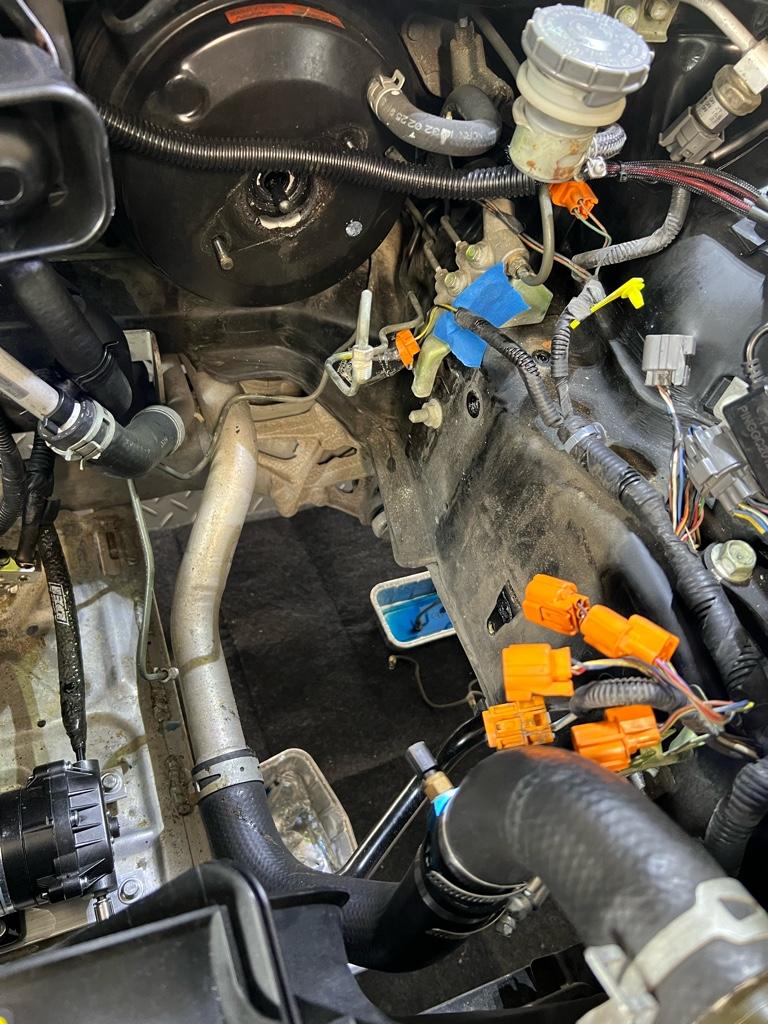
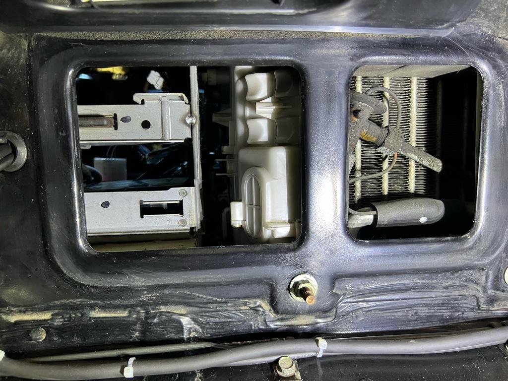
ABS computer
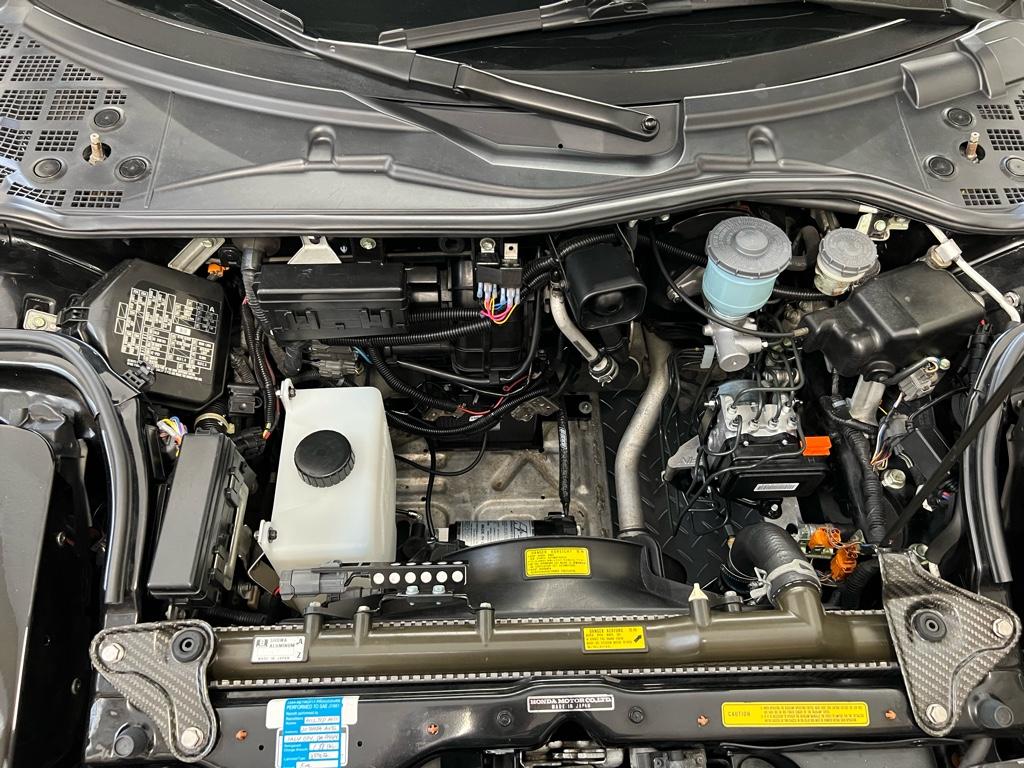
I thought this was going to be a total pain to remove based on Big McLargeHuge's build thread + the manual, but it came out with minimal fight. For context, it's the box on the top here with the orange sockets:
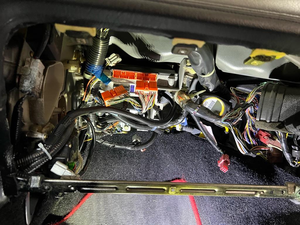
3 of the 4 bolts for the ABS computer are easy to get to without removing anything. For the 4th, I took out the cruise computer below the ABS computer, then used a ratchet way back on the left side of the ABS computer.
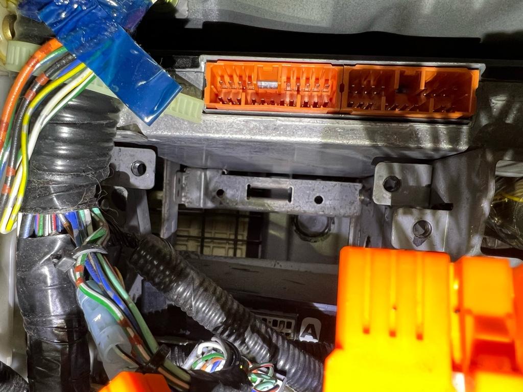
I loosened the top left bolt on the cage and was able to wiggle the ABS computer out. This is probably a lot easier if you dont have EPS, which has a computer (IIRC) below the cruise controller. And it's out:
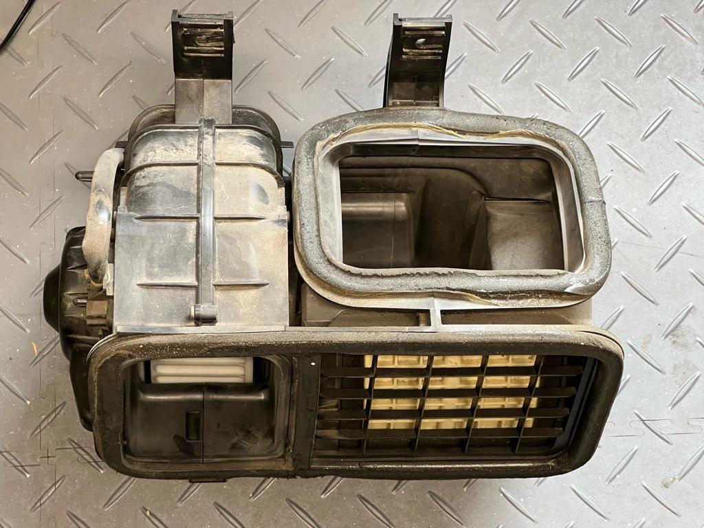
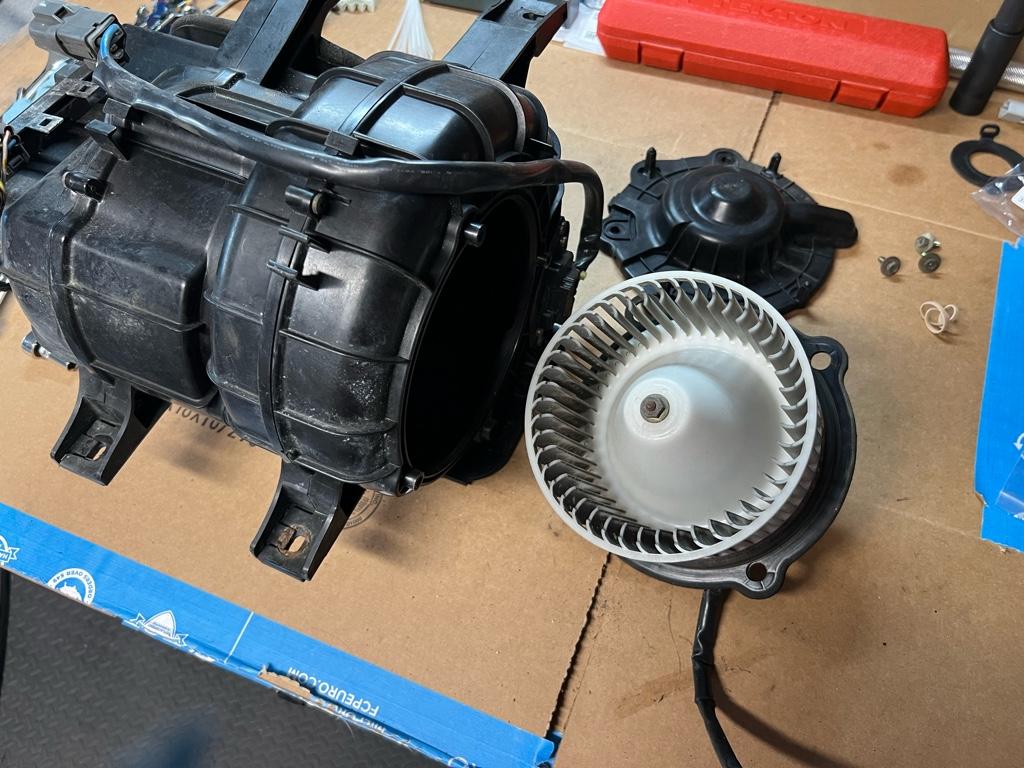
Blower motor
After removing the 4 bolts for the blower motor, it was still hard to get out for me for 2 reasons: the weather strip had adhered to the body, and there is a plastic stud on the drivers side of the blower motor in a rubber grommet. It looked like the rubber grommet pulled out of the bracket, but I was ultimately able to just maneuver the blower motor out without removing the grommet.
Very dirty inside and out
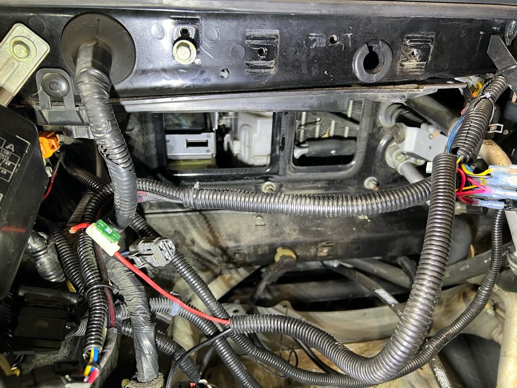
Then cleaned up back there
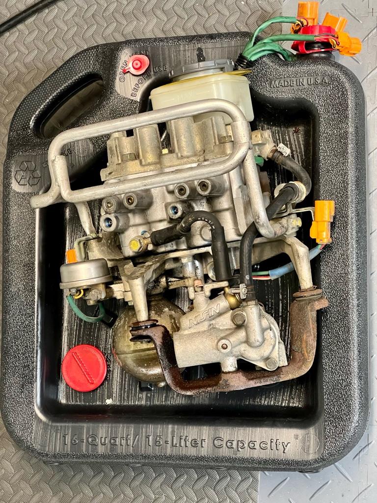
ABS unit
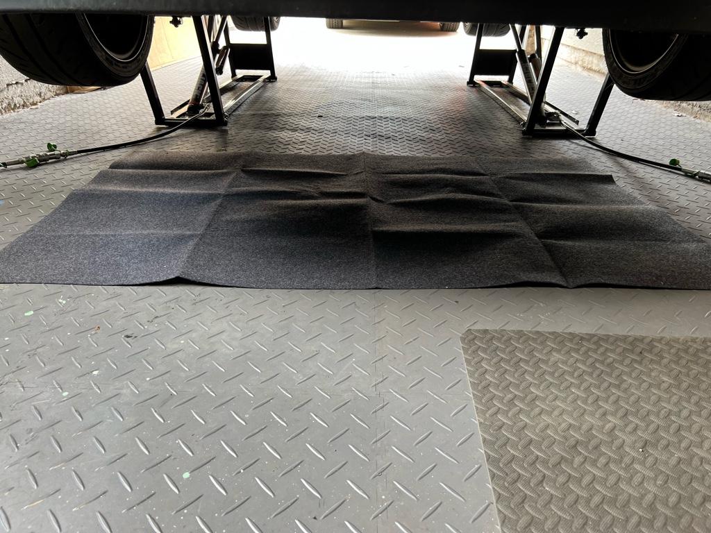
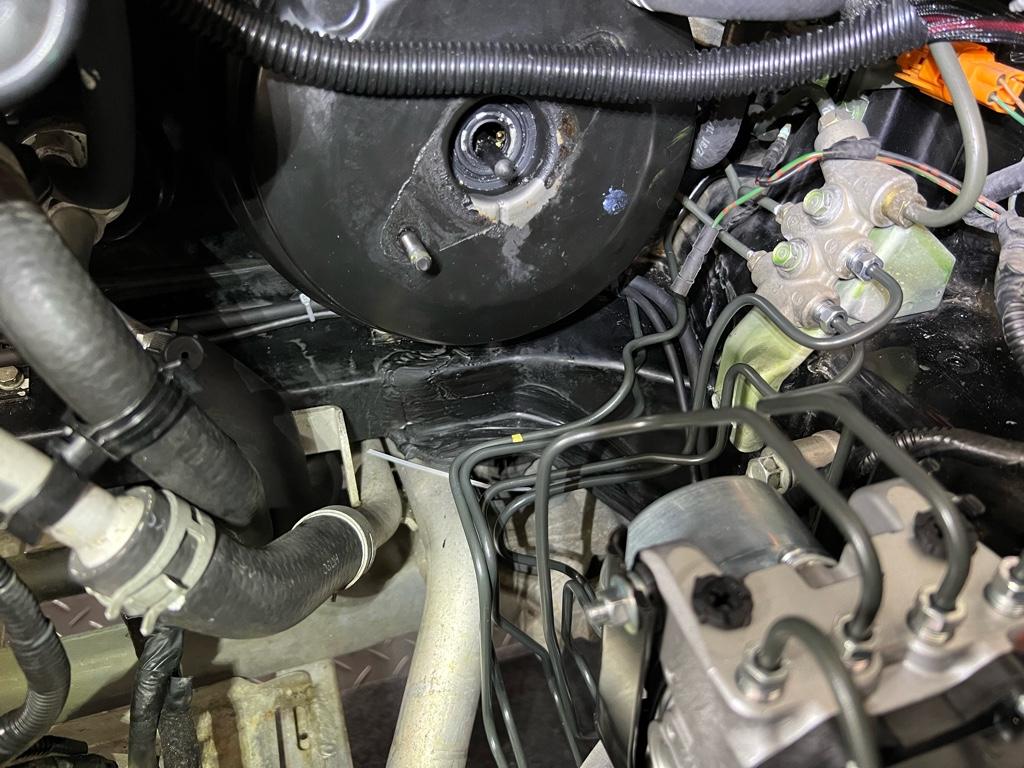
This sucka. I was incredibly paranoid about getting brake fluid on anything while removing the ABS unit. I went slow and did a lot of cleaning during the process
I had a couple oil spill mats that helped a lot
Front brake lines out
Unit out!
Day 1 was removal day. I got everything out of the car and managed to do a little cleaning.
The steps:
* Remove glovebox
* Remove ABS computer: not as bad as I was expecting
* Remove battery: mine is small, but still in the way
* Remove WMI tank
* Remove blower motor
* Unbolt cruise box at the bottom bracket, lay on cowl
* Turkey baster all the fluid I could
* Drain brakes fluid at the front calipers
* Remove front brake lines
* Remove old master cylinder
* Remove old ABS unit
* Remove old front wheel hard lines, I bent the F out of them to get them out
* Clean the chassis behind the abs and blower motor
* Assess harness situation, where should it go?
I didn't take a ton of removal photos, but a couple
ABS computer
I thought this was going to be a total pain to remove based on Big McLargeHuge's build thread + the manual, but it came out with minimal fight. For context, it's the box on the top here with the orange sockets:
3 of the 4 bolts for the ABS computer are easy to get to without removing anything. For the 4th, I took out the cruise computer below the ABS computer, then used a ratchet way back on the left side of the ABS computer.
I loosened the top left bolt on the cage and was able to wiggle the ABS computer out. This is probably a lot easier if you dont have EPS, which has a computer (IIRC) below the cruise controller. And it's out:
Blower motor
After removing the 4 bolts for the blower motor, it was still hard to get out for me for 2 reasons: the weather strip had adhered to the body, and there is a plastic stud on the drivers side of the blower motor in a rubber grommet. It looked like the rubber grommet pulled out of the bracket, but I was ultimately able to just maneuver the blower motor out without removing the grommet.
Very dirty inside and out
Then cleaned up back there
ABS unit
This sucka. I was incredibly paranoid about getting brake fluid on anything while removing the ABS unit. I went slow and did a lot of cleaning during the process
I had a couple oil spill mats that helped a lot
Front brake lines out
Unit out!
ABS Day 2: Install
The steps:
* Relieve pressure in old unit, mine had no foam or pressure!
* Take old unit apart to get to the old bracket
* Clean the old bracket: a lot of brake cleaner and a wire brush
* Assemble the new abs modulator with old bracket outside the car. New prop valve, etc.
* Install all hard lines to the new modulator hand tight except 4: MC front and rear, both front wheel lines
* Install new RF and LF hard lines into the wheel wells. Total pain. RF was harder, but I bent the LF one more to make it fit
* Install new ABS modulator and lines onto chassis
* Hook up all lines hand tight except master cylinder
* Get wiring harness into the cabin
* Figure out routing of harness, remove and install ABS unit like 3 times
* Add power plug for modulator to harness
* Zip tie the harness in its final location
* Torque the 2 rear prop valve lines with master cylinder out
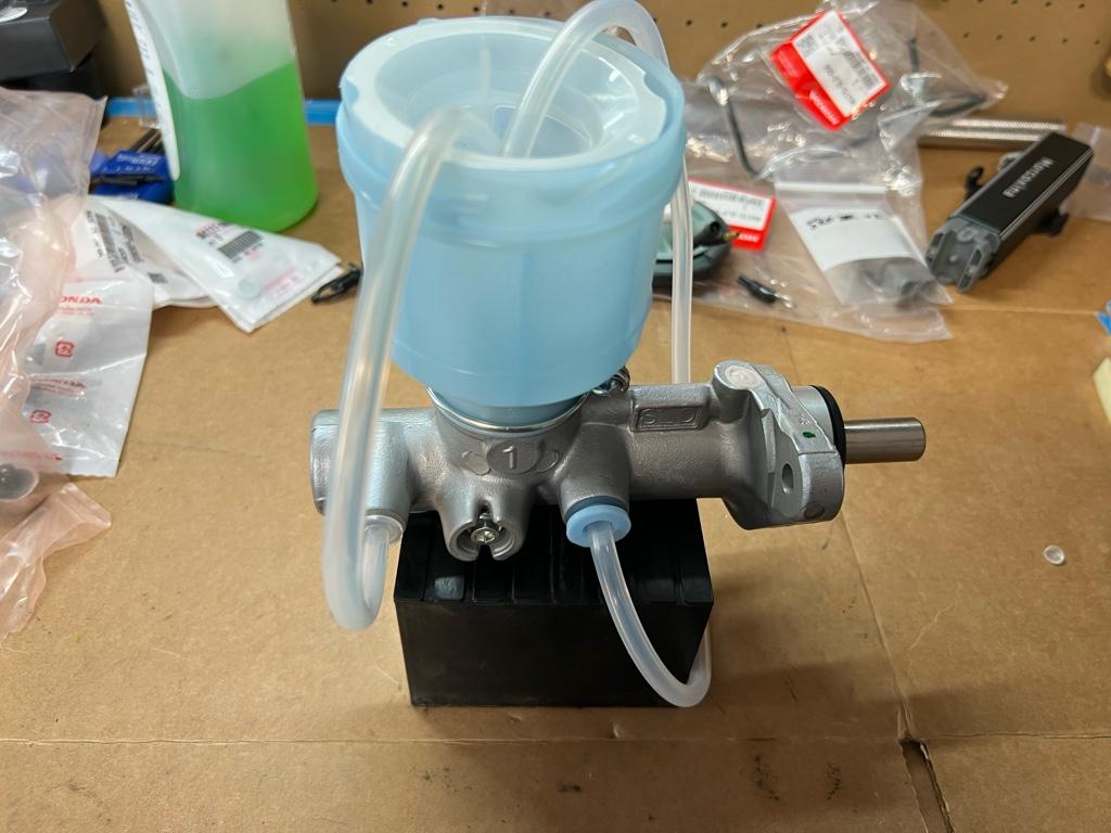
* Bench bleed new master cylinder
* Attempt to install the MC with silicone hoses
* Take out MC and hook up some old hard lines to it for less leakage
* Install new master cylinder
* Install new master cylinder rear line
* Install new master cylinder front line
* Torque remaining lines in the frunk
* Install new front SS lines. Kind of a production getting the hard lines in the right place
* Remove old stock rear lines
* Install new Goodridge SS lines
* Install Speedbleeders all around
* Bleed brakes 2x
* Wheels back on, clean up, car on the ground
Install new ABS unit
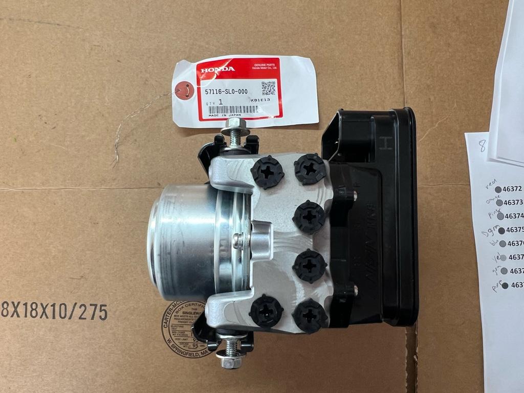
First thing here was to tear apart the old unit to get this aluminum bracket. It was crazy dirty, but a lot of brake cleaner and a wire brush had it looking pretty good:
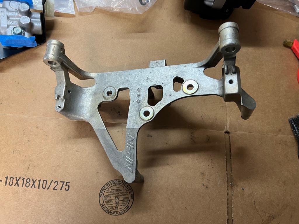
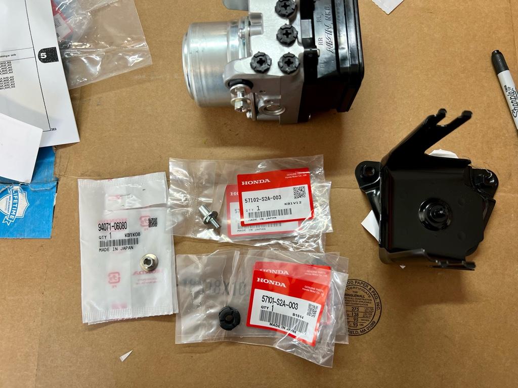
Next was assembling the new unit with the bracket plus all the bits from the Mita kit
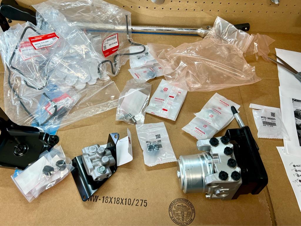
At first the modulator mounting parts were confusing, but there are three grommets and little standoffs that fit in the grommets.
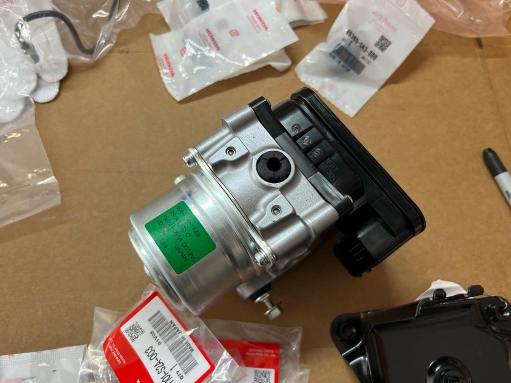
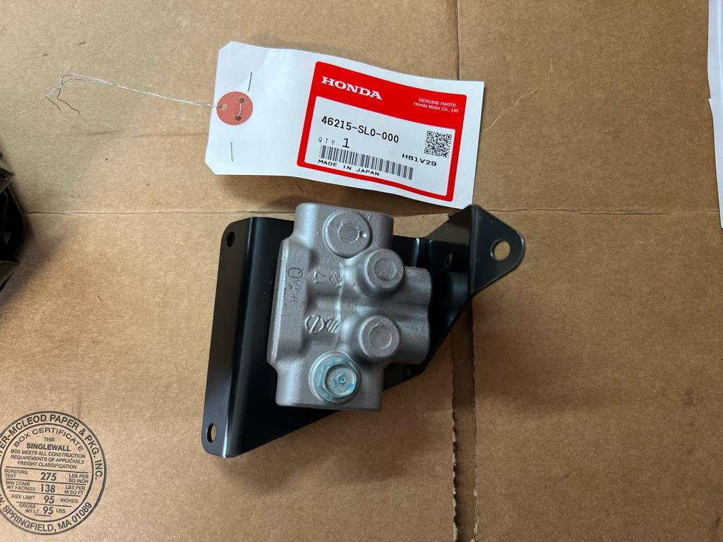
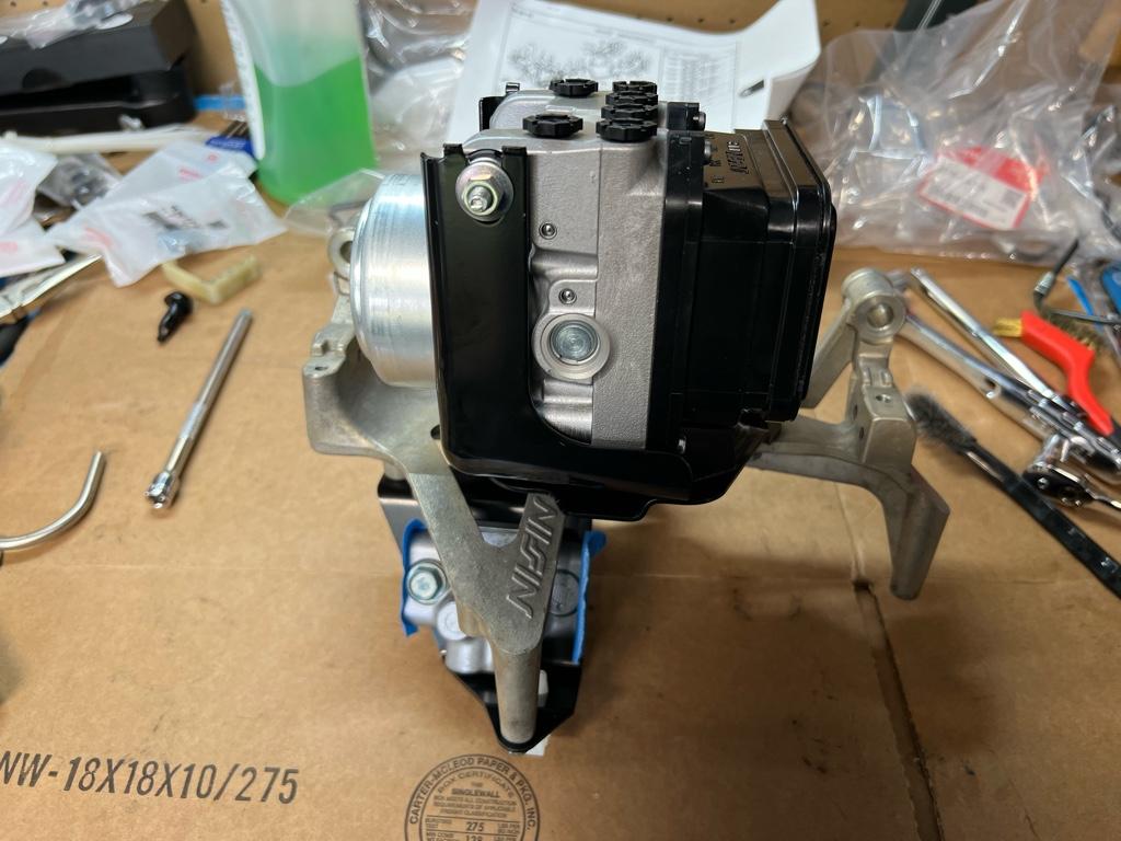
Once the modulator + proportioning valve are all on the old bracket, you can install like 4 lines hand tight before bolting the whole thing in the car. Note, I did not install the MC lines hand tight here cause they would be in the way. The Mita instructions were really only helpful here as they had pics of which lines via PN go where
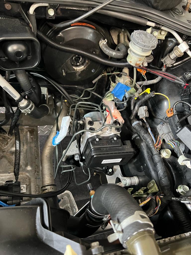
Then the unit bolted up in the car.
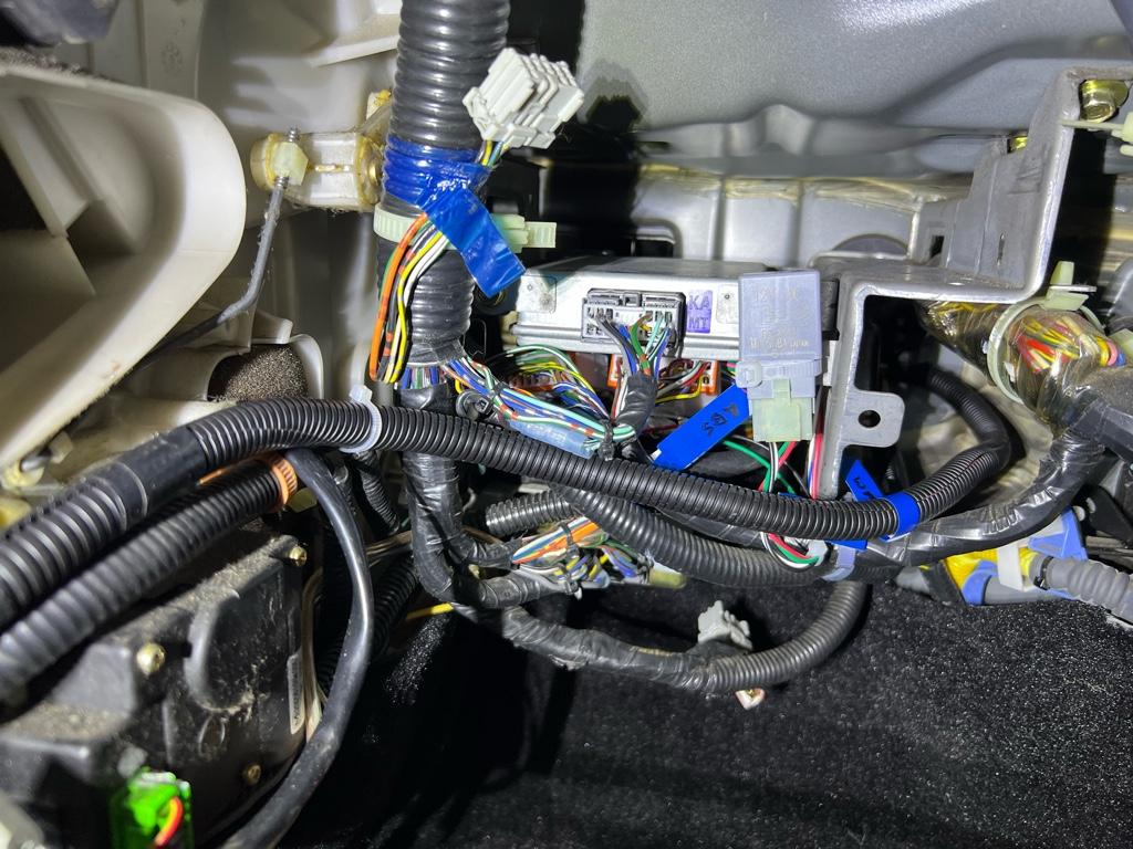
Install KSP harness
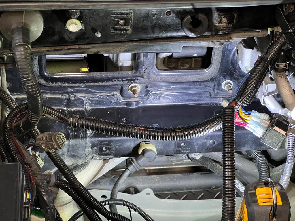
Then with the modulator bolted up in the car, it was time to route the KSP harness. I decided to send it through a little grommet that put the harness right where the EPS computer would be behind the glovebox. It was unclear how much of the harness would end up in the cabin. Turns out a lot. Like at least a 18".
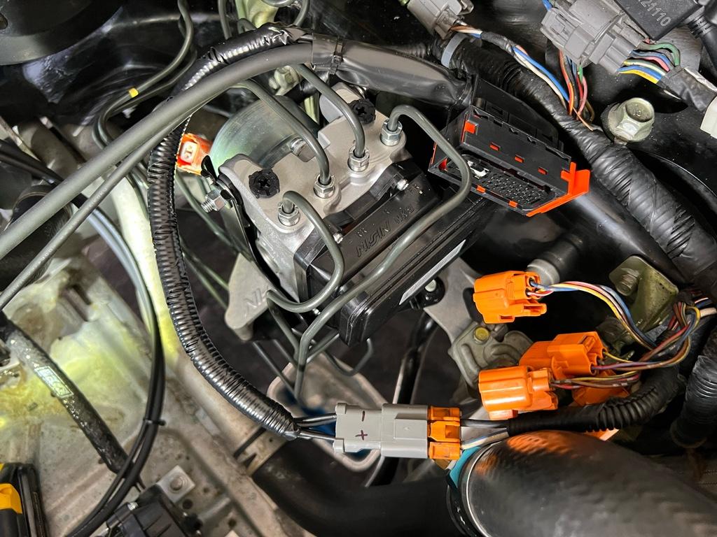
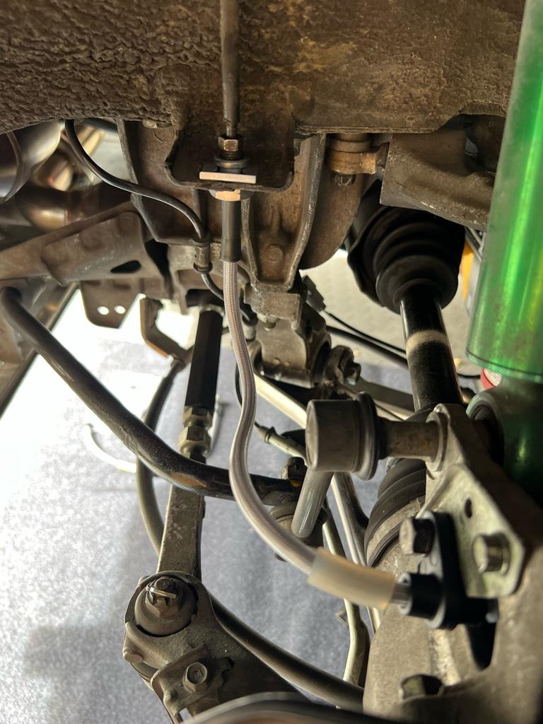
One thing to note is that I zip-tied the harness to the brake lines. After getting everything together, I realized that the hard lines lines can get crazy hot. I'm not glowing the brakes on the regular, I guess, and they are covered in what looks like high temp sheath, but it's possible. Maybe a mistake? Any thoughts? I'm considering going back in there and like putting some heat shield around them, moving them, or something else?
Anyway, I routed the harness above the right side hard line, and below the left side hardline. I experimented with different routing here, and this felt like the best deal. It required me to remove and install the ABS unit at least 3 times. not ideal, but I wanted it to feel good. Again, it touches the hard line here
Now to get power to the thing. The KSP harness comes with a couple eyelets for power and ground. The instructions say to run them into the main fusebox, but that is jank. The Mita instructions say that you can reuse the old ABS unit's power plug. This is where the "2 pin Yazaki 58 Connector X Type" plug comes in. I got 2 from cycleterminal
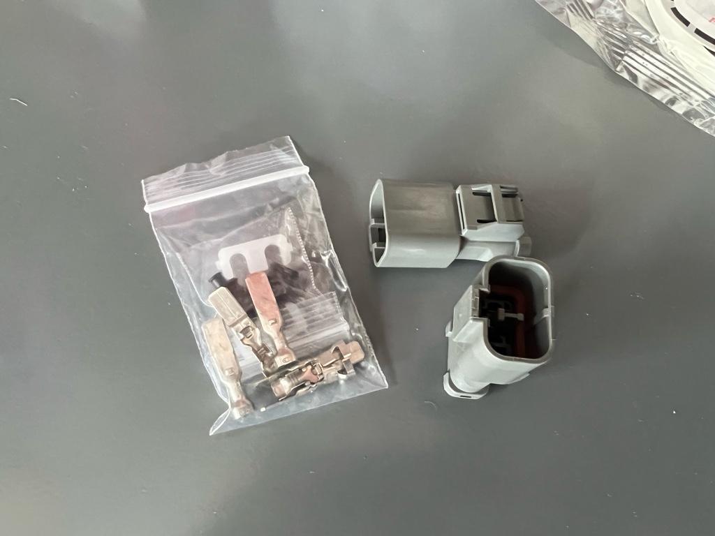
The power wires in the KSP harness are super long, and the ground is super short, so you need to shorten the power by like 2 feet and lengthen the ground by a couple inches. This is what I ended up with, it ultimately runs under the modulator, but here it is mocked up
Then I pulled the old harness bracket off the old unit to hold the plug. Here's how it's routed
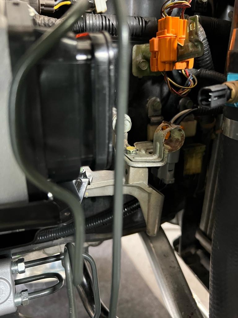
Also a thing to note here is that you can plug the old orange 3-pin connectors together, then connect them to the old bracket on the frame rail. Looks like they do something, but they don’t!
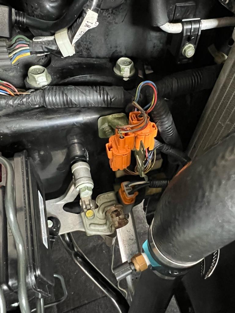
Does anyone know if this bracket is on the newer cars? I really want to buy a new one, but cant find a part number...
Bench Bleed
Ohkay, here was my bench bleed setup. Fill it with fluid and pump the MC with my palm. It was quite precarious, but it worked. I ended up doing it on an oil mat, and it was messy, so no other pics
Castrol SRF fluid. I debated between this and Motul 660 (or 600, I cant remember). The SRF has a really high wet boiling point, so I went for it. It also seems like it's regarded by The Internet as The Brake Fluid with Motul a close 2nd. I really only ended up needing like 1.1 liters, so annoying I had to buy two full liters. But apparently it has a ~1 year shelf life after opening, so I can use the rest for bleeding top-ups until a full flush comes around.
Brake lines / speedbleeders
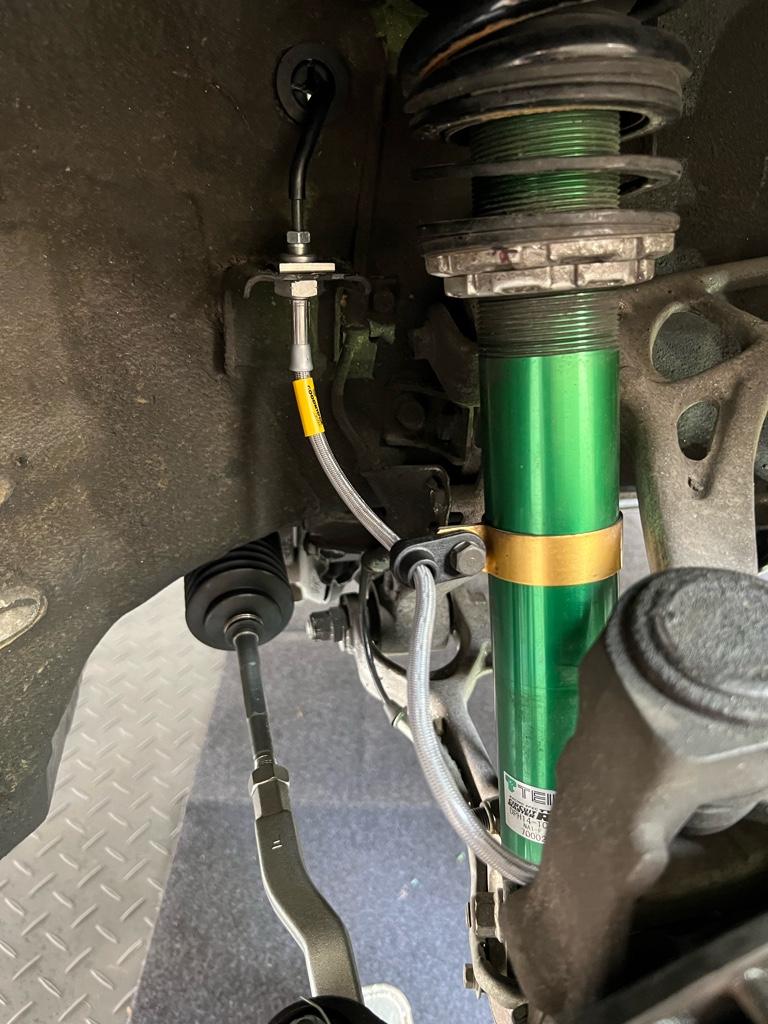
Alright, almost done with day 2 now. Penultimate thing was installing the brake lines to the calipers. I put new Goodridge lines and stainless speedbleeders all around.
The fronts. Not shown: 30 min of fiddling with each side’s new hard line here to get them in the right orientation. I managed to get them in the center of the grommets through the wheel wells tho!
And the rear with new speedbleeder
Bleed
Last thing was to bleed the brakes. I bled each caliper twice. I ended up doing the X pattern starting with RR, but then read later I could start with the closest ones on the new system. Oh well, wasted some fluid. With the speedbleeders this was pretty easy, but still easier with another person. I had the girl sit in the car and gingerly pump while I monitored fluid levels.
This was the setup. Very clean, nary a spilled drop:
The steps:
* Relieve pressure in old unit, mine had no foam or pressure!
* Take old unit apart to get to the old bracket
* Clean the old bracket: a lot of brake cleaner and a wire brush
* Assemble the new abs modulator with old bracket outside the car. New prop valve, etc.
* Install all hard lines to the new modulator hand tight except 4: MC front and rear, both front wheel lines
* Install new RF and LF hard lines into the wheel wells. Total pain. RF was harder, but I bent the LF one more to make it fit
* Install new ABS modulator and lines onto chassis
* Hook up all lines hand tight except master cylinder
* Get wiring harness into the cabin
* Figure out routing of harness, remove and install ABS unit like 3 times
* Add power plug for modulator to harness
* Zip tie the harness in its final location
* Torque the 2 rear prop valve lines with master cylinder out
* Bench bleed new master cylinder
* Attempt to install the MC with silicone hoses
* Take out MC and hook up some old hard lines to it for less leakage
* Install new master cylinder
* Install new master cylinder rear line
* Install new master cylinder front line
* Torque remaining lines in the frunk
* Install new front SS lines. Kind of a production getting the hard lines in the right place
* Remove old stock rear lines
* Install new Goodridge SS lines
* Install Speedbleeders all around
* Bleed brakes 2x
* Wheels back on, clean up, car on the ground
Install new ABS unit
First thing here was to tear apart the old unit to get this aluminum bracket. It was crazy dirty, but a lot of brake cleaner and a wire brush had it looking pretty good:
Next was assembling the new unit with the bracket plus all the bits from the Mita kit
At first the modulator mounting parts were confusing, but there are three grommets and little standoffs that fit in the grommets.
Once the modulator + proportioning valve are all on the old bracket, you can install like 4 lines hand tight before bolting the whole thing in the car. Note, I did not install the MC lines hand tight here cause they would be in the way. The Mita instructions were really only helpful here as they had pics of which lines via PN go where
Then the unit bolted up in the car.
Install KSP harness
Then with the modulator bolted up in the car, it was time to route the KSP harness. I decided to send it through a little grommet that put the harness right where the EPS computer would be behind the glovebox. It was unclear how much of the harness would end up in the cabin. Turns out a lot. Like at least a 18".
One thing to note is that I zip-tied the harness to the brake lines. After getting everything together, I realized that the hard lines lines can get crazy hot. I'm not glowing the brakes on the regular, I guess, and they are covered in what looks like high temp sheath, but it's possible. Maybe a mistake? Any thoughts? I'm considering going back in there and like putting some heat shield around them, moving them, or something else?
Anyway, I routed the harness above the right side hard line, and below the left side hardline. I experimented with different routing here, and this felt like the best deal. It required me to remove and install the ABS unit at least 3 times. not ideal, but I wanted it to feel good. Again, it touches the hard line here
Now to get power to the thing. The KSP harness comes with a couple eyelets for power and ground. The instructions say to run them into the main fusebox, but that is jank. The Mita instructions say that you can reuse the old ABS unit's power plug. This is where the "2 pin Yazaki 58 Connector X Type" plug comes in. I got 2 from cycleterminal
The power wires in the KSP harness are super long, and the ground is super short, so you need to shorten the power by like 2 feet and lengthen the ground by a couple inches. This is what I ended up with, it ultimately runs under the modulator, but here it is mocked up
Then I pulled the old harness bracket off the old unit to hold the plug. Here's how it's routed
Also a thing to note here is that you can plug the old orange 3-pin connectors together, then connect them to the old bracket on the frame rail. Looks like they do something, but they don’t!
Does anyone know if this bracket is on the newer cars? I really want to buy a new one, but cant find a part number...
Bench Bleed
Ohkay, here was my bench bleed setup. Fill it with fluid and pump the MC with my palm. It was quite precarious, but it worked. I ended up doing it on an oil mat, and it was messy, so no other pics
Castrol SRF fluid. I debated between this and Motul 660 (or 600, I cant remember). The SRF has a really high wet boiling point, so I went for it. It also seems like it's regarded by The Internet as The Brake Fluid with Motul a close 2nd. I really only ended up needing like 1.1 liters, so annoying I had to buy two full liters. But apparently it has a ~1 year shelf life after opening, so I can use the rest for bleeding top-ups until a full flush comes around.
Brake lines / speedbleeders
Alright, almost done with day 2 now. Penultimate thing was installing the brake lines to the calipers. I put new Goodridge lines and stainless speedbleeders all around.
The fronts. Not shown: 30 min of fiddling with each side’s new hard line here to get them in the right orientation. I managed to get them in the center of the grommets through the wheel wells tho!
And the rear with new speedbleeder
Bleed
Last thing was to bleed the brakes. I bled each caliper twice. I ended up doing the X pattern starting with RR, but then read later I could start with the closest ones on the new system. Oh well, wasted some fluid. With the speedbleeders this was pretty easy, but still easier with another person. I had the girl sit in the car and gingerly pump while I monitored fluid levels.
This was the setup. Very clean, nary a spilled drop:
Last edited:
ABS Day 3: Finish up
By day 3, the car was on the ground and close to being drivable. Day 3 was the last day and all about finishing + working out any kinks.
The steps
* Clean + re-weather-strip blower motor
* Clean old weather strip from firewall
* Clean cabin air duct
* Install cabin air filter
* Install blower motor
* Install battery
* Does it work? No.
* Add ABS relay jumper wire
* Try again, does it work? Yes!
* Drive it!! Brakes feel better!!
* Bleed brakes one more time
* Tidy up wiring under the dash
* Install glovebox
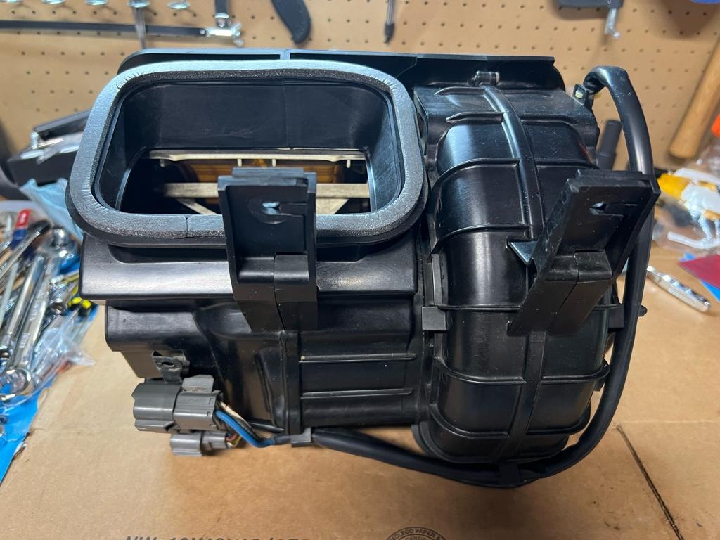
Blower motor
This thing was dirty. Before

During. I pulled off the motor to inspect and further clean.
After. The old weather stripping pulled off really cleanly; a nice surprise.
Firewall cleaning
I wanted a legit seal for the new weather stripping, so I had to get all the old gunk off.
After
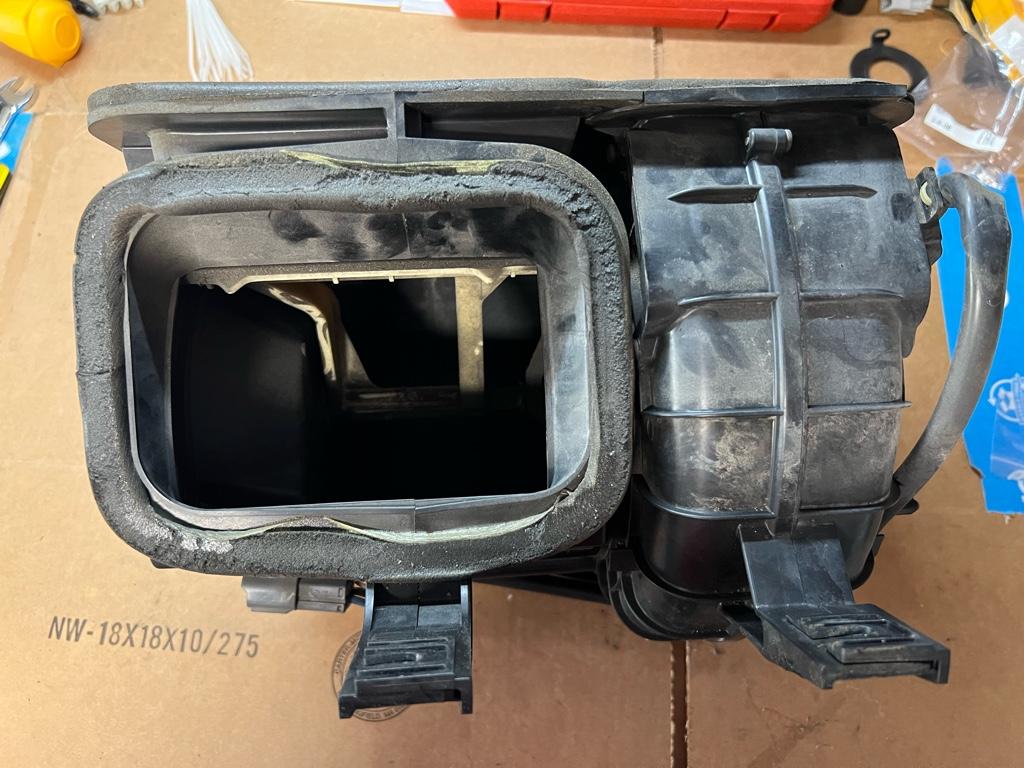
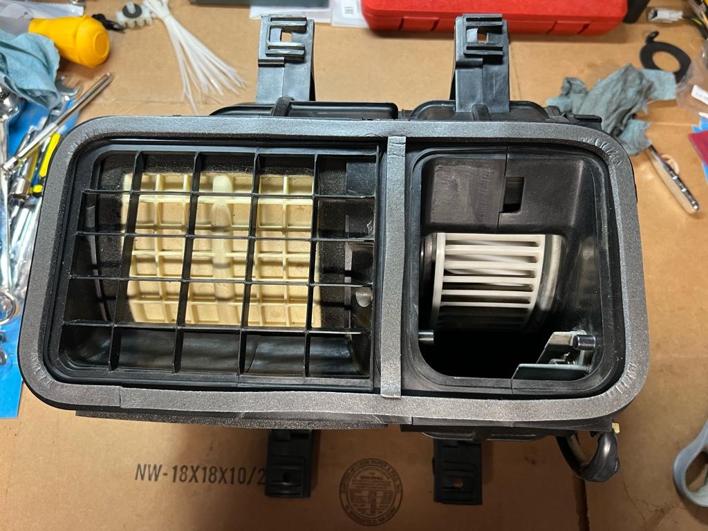
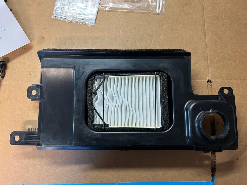
Cabin duct / Umbrella fresh air
This thing was hanging by one clip and was dirty. I got a Mita cabin air filter kit to install While I'm In There. It came out for proper cleaning and filter install.
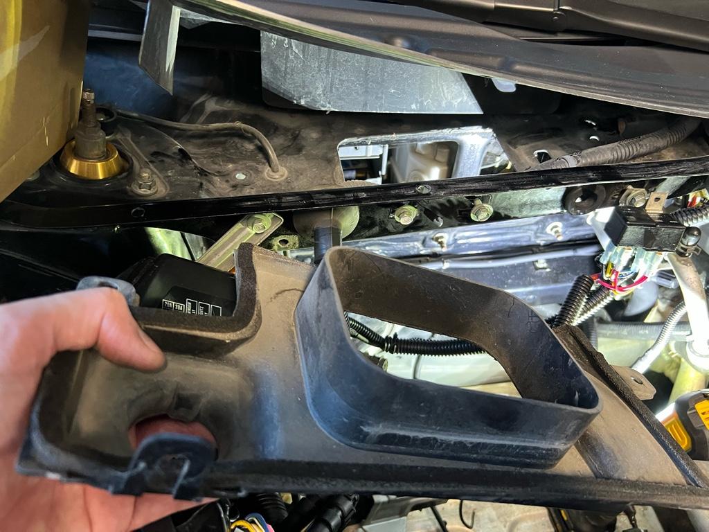
To be clear, it is Umbrella Fresh Air.
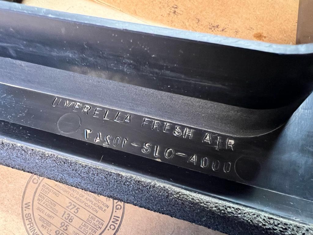
Now clean and ready for Mita filter install
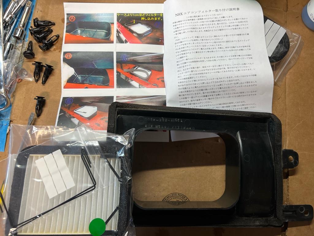
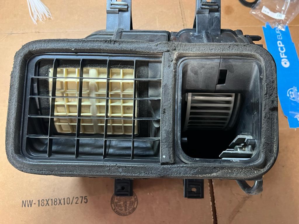
Well, it turns out the filter doesn't really fit. It is both wider and shorter than it should be. Did anyone actually test fit this thing? Whatever, it mostly fits. You can see the shortness gap on the left, and the waves in the filter on the right cause it is too wide. They give you JDM weather stripping to fill the gaps lol.
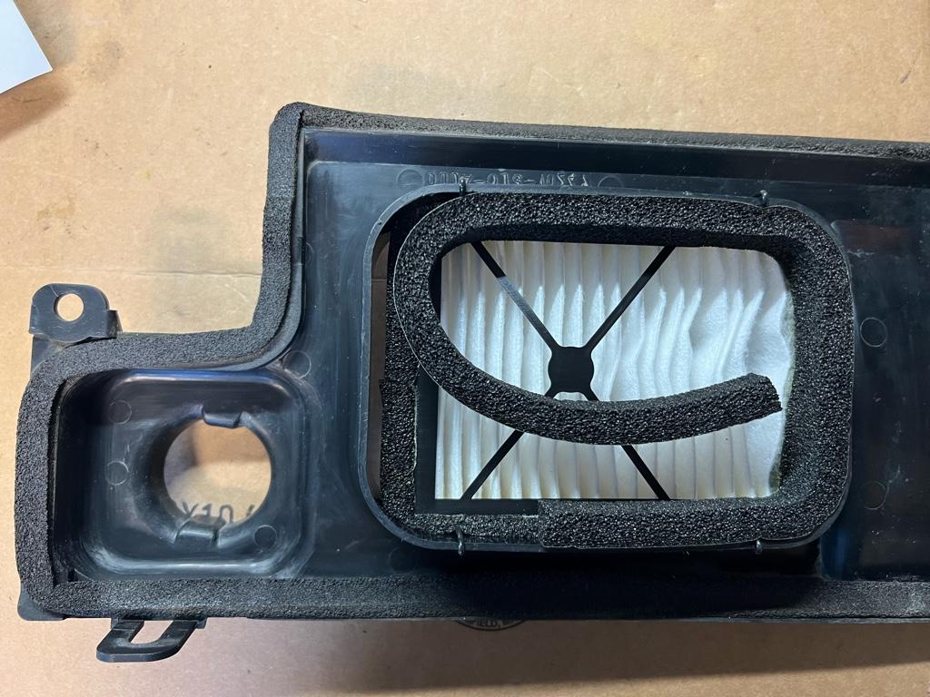
Fully weather stripped
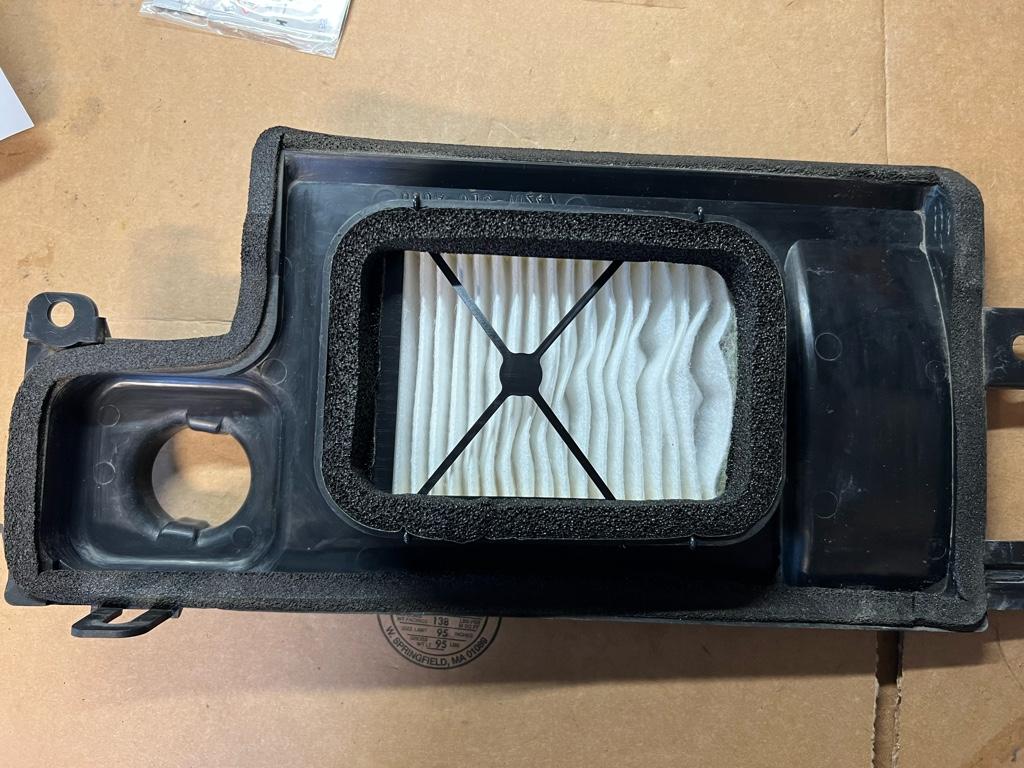
Squished, jank, derp, I will buy the facebook guy's filter next time.
Jumper
I checked everything and started it up. ABS light on! Shit! WTF!
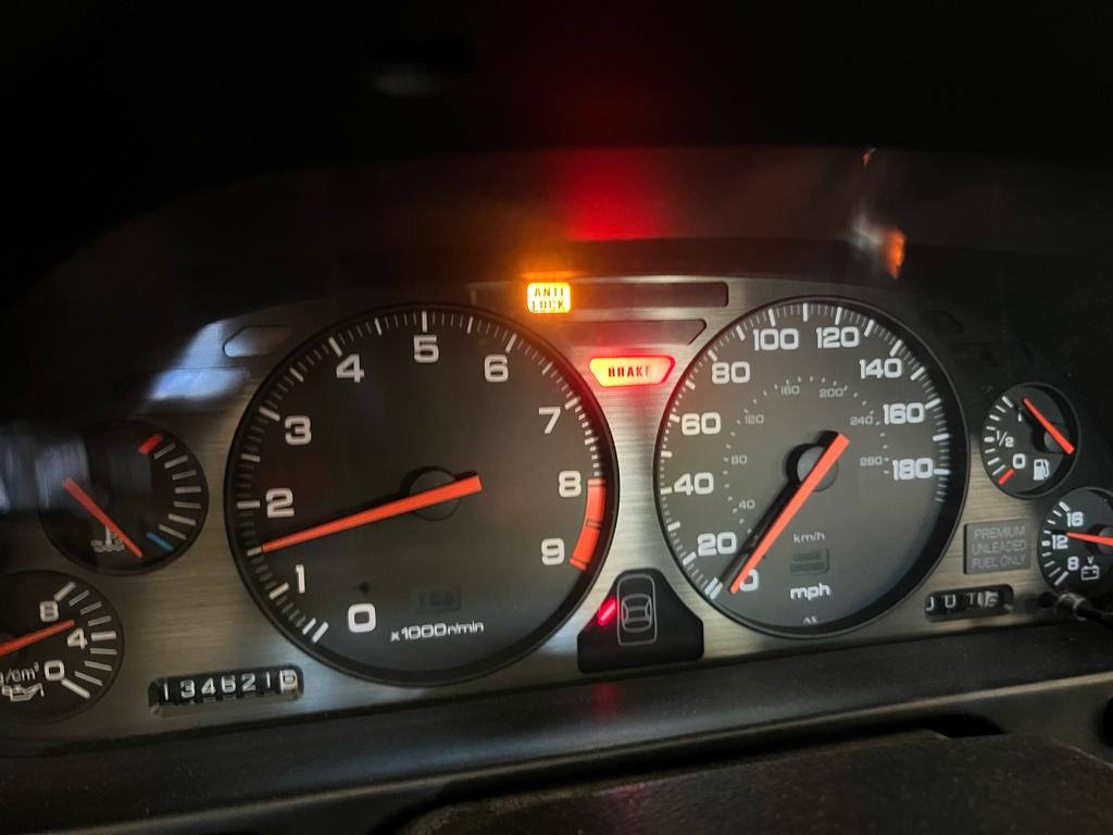
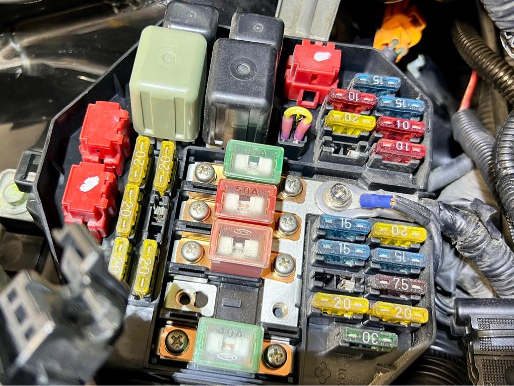
Well, I totally blanked on the jumper in the ABS relay spot. So I made one and installed it. I looked at 10 pics of this thing but was still unclear as to which blades it went into. Pull the ABS relay out, then it goes in the blades closest to the front of the car. Note the yellow jumper here on the top of the pic:
Drive itt
The brakes felt fine in the driveway, so I took it out. I was worried that with my minimal bleeding they'd be pretty soft, but the brakes immediately felt great. Speedbleeders FTW.
Then some brake pedal mashing and ABS worked out of the gate, yay! This thing can fookin stop. The RT660s were a lot harder to overwhelm than the old direzzas...
When I got back I bled them again, front first this time. Many tiny bubbles came out of the rear. Progress.
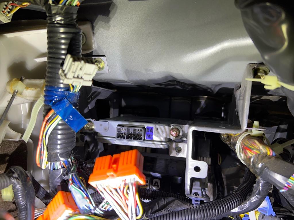
Harness tidy + interior back together
I tidied up the harness and reinstalled the interior last just in case there were issues I had to hunt down. None, though, so back together it went.
I only took one pic of the final resting location of the harness. I coiled it up, zip-tied the unruly bits, labeled it, and put it under the cruise computer where the EPS computer would be. The relay is zip-tied there in the front to a metal tab for I-dont-know-what. The goal was to make the relay not bounce around, but easyish to access in case it needed replacing.
Done! Fin!
That's it! I'm extremely happy to have it done, working, have no leaks, etc. I drove the car a good amount this morning after the 3rd bleed, and the brakes feel even better, sweet!
By day 3, the car was on the ground and close to being drivable. Day 3 was the last day and all about finishing + working out any kinks.
The steps
* Clean + re-weather-strip blower motor
* Clean old weather strip from firewall
* Clean cabin air duct
* Install cabin air filter
* Install blower motor
* Install battery
* Does it work? No.
* Add ABS relay jumper wire
* Try again, does it work? Yes!
* Drive it!! Brakes feel better!!
* Bleed brakes one more time
* Tidy up wiring under the dash
* Install glovebox
Blower motor
This thing was dirty. Before
During. I pulled off the motor to inspect and further clean.
After. The old weather stripping pulled off really cleanly; a nice surprise.
Firewall cleaning
I wanted a legit seal for the new weather stripping, so I had to get all the old gunk off.
After
Cabin duct / Umbrella fresh air
This thing was hanging by one clip and was dirty. I got a Mita cabin air filter kit to install While I'm In There. It came out for proper cleaning and filter install.
To be clear, it is Umbrella Fresh Air.
Now clean and ready for Mita filter install
Well, it turns out the filter doesn't really fit. It is both wider and shorter than it should be. Did anyone actually test fit this thing? Whatever, it mostly fits. You can see the shortness gap on the left, and the waves in the filter on the right cause it is too wide. They give you JDM weather stripping to fill the gaps lol.
Fully weather stripped
Squished, jank, derp, I will buy the facebook guy's filter next time.
Jumper
I checked everything and started it up. ABS light on! Shit! WTF!
Well, I totally blanked on the jumper in the ABS relay spot. So I made one and installed it. I looked at 10 pics of this thing but was still unclear as to which blades it went into. Pull the ABS relay out, then it goes in the blades closest to the front of the car. Note the yellow jumper here on the top of the pic:
Drive itt
The brakes felt fine in the driveway, so I took it out. I was worried that with my minimal bleeding they'd be pretty soft, but the brakes immediately felt great. Speedbleeders FTW.
Then some brake pedal mashing and ABS worked out of the gate, yay! This thing can fookin stop. The RT660s were a lot harder to overwhelm than the old direzzas...
When I got back I bled them again, front first this time. Many tiny bubbles came out of the rear. Progress.
Harness tidy + interior back together
I tidied up the harness and reinstalled the interior last just in case there were issues I had to hunt down. None, though, so back together it went.
I only took one pic of the final resting location of the harness. I coiled it up, zip-tied the unruly bits, labeled it, and put it under the cruise computer where the EPS computer would be. The relay is zip-tied there in the front to a metal tab for I-dont-know-what. The goal was to make the relay not bounce around, but easyish to access in case it needed replacing.
Done! Fin!
That's it! I'm extremely happy to have it done, working, have no leaks, etc. I drove the car a good amount this morning after the 3rd bleed, and the brakes feel even better, sweet!


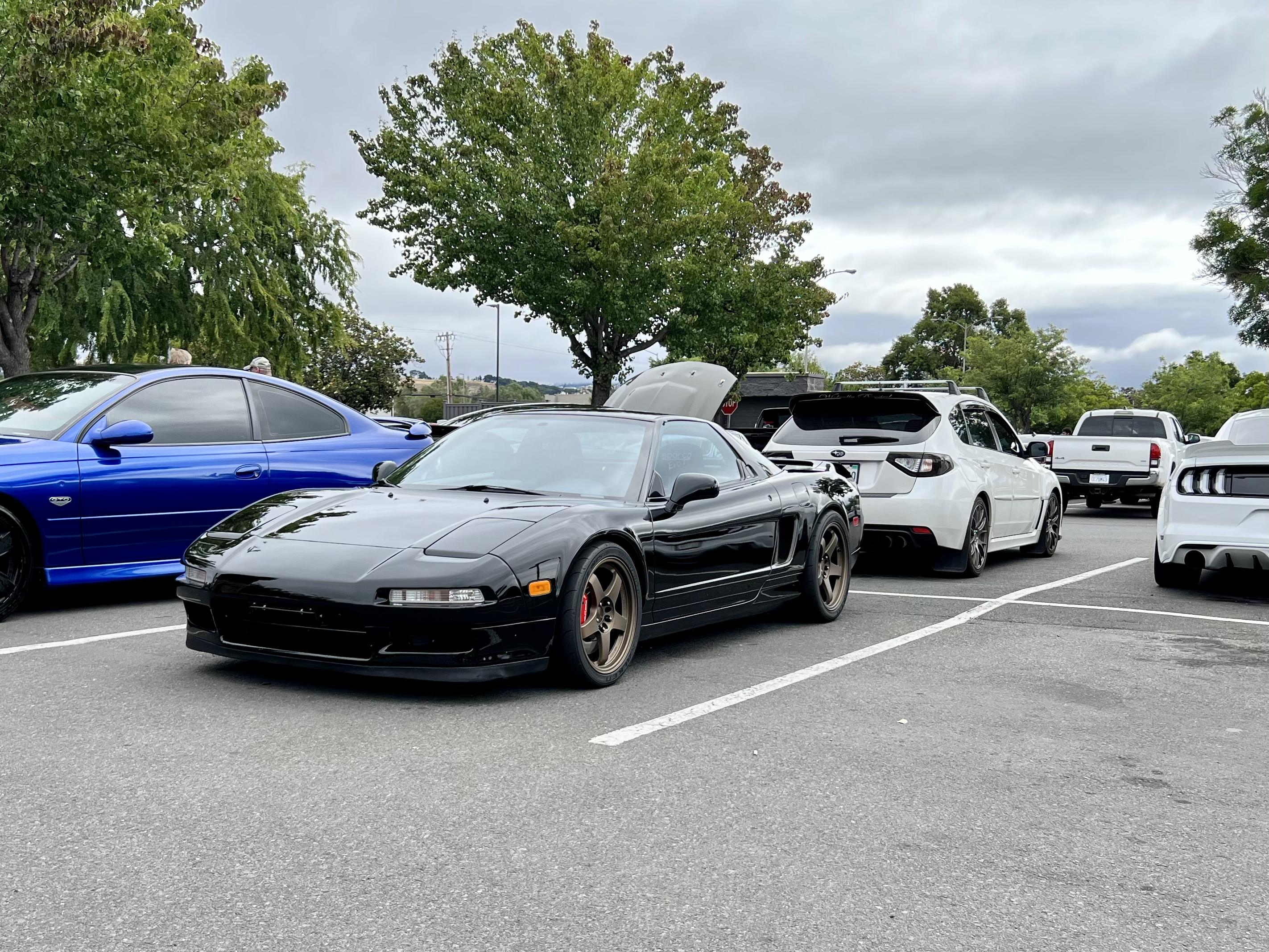
I cannot get over how good those wheels look!
Thanks! Same, I really love them. And they cause a lot of confusion which is lulzy. So many Nissan people come over and are like “um, are those….?”
It's been a while but I have been tinkering. I’ve been driving it a whole bunch but also trying understand the air temps, how they affect things, and generally working out how to get them down.
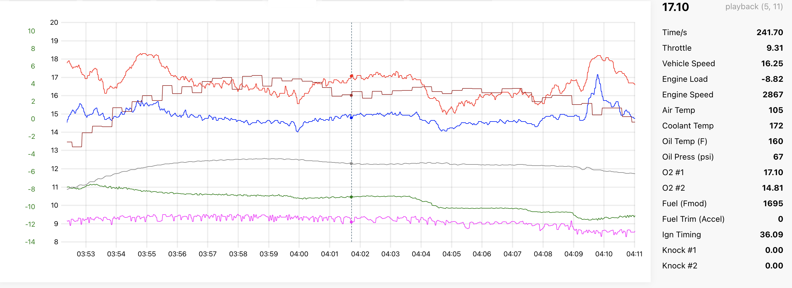
A couple weeks ago I had made some changes to the air temp sensor and I took the car out to test. I barely got out of the neighborhood and it started misfiring. The front bank all of a sudden went crazy lean. Shiiiiiit.
You can see it here, I shift into 3rd and O2 #1 goes lean. Usually the front bank (O2 1: red line) is slightly richer than the rear (O2 2: blue line), but not on this day.
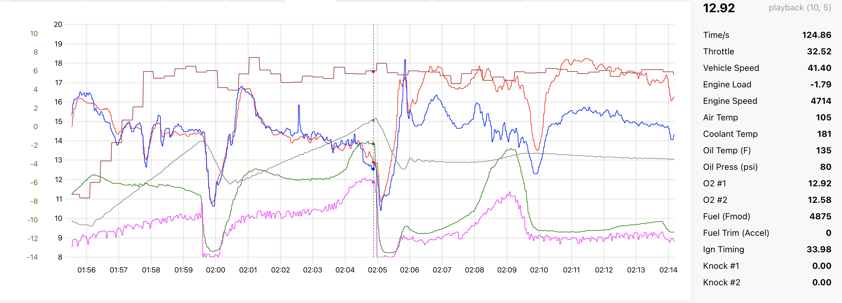
Obviously freaked out, I limped it home. You can see even when lightly cruising the front bank was way leaner (red line) than the rear bank (blue line):
I narrowed it down to cylinder 4 by pulling injector plugs until there was no change. I checked the usual: oil, coolant, and everything looked fine. But I still had prepared for the worst, I dunno, blown ringlands or something. I bought compression and leak down testers. That week there were a lot of searches to figure out how much a rebuild at SoS might be... (spoiler alert: not cheap)
It was running lean, so my thought was that the number 4 injector wasn’t firing. When I messed with the air temp sensor, I had to move around the front bank injector wiring. Did I disrupt a butt connector? Did that injector go bad?
I started this thread asking for help.
On the thread, a couple people mentioned that even no ignition on one cylinder would cause a lean condition. At first this was not so intuitive, but now it makes sense. The idea is that along with all the unburnt fuel coming out, there would also be unburnt oxygen mixing with the exhaust from the other cylinders, and ultimately outweighing the extra fuel: lean reading.
I bought a whole bunch of tools + parts including ingnition-related things based on feedback from that thread. My goal was to fix, or at the very least, understand it the next weekend. I was supposed to take the car to an event the weekend after, so I wanted to solve it as soon as I could.
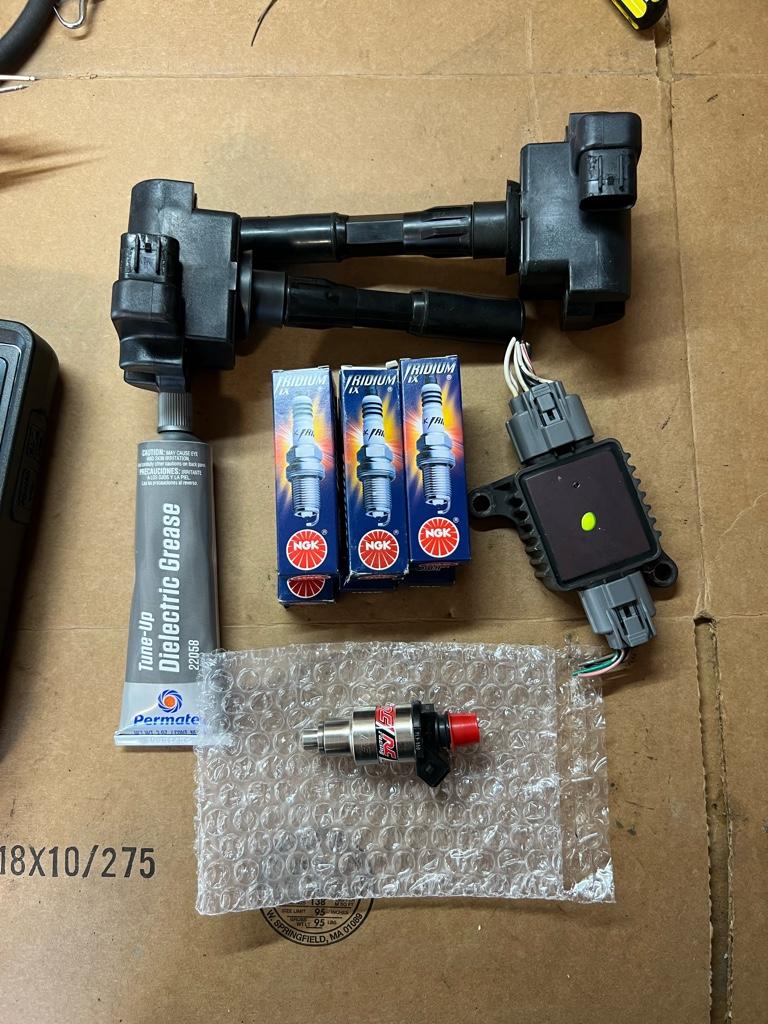
Fortunately this one had a quick, happy ending. Unlike most things (in life?), the easiest and first thing I tried did the trick. I replaced the number 4 plug and coil. 10 minutes of work and it was totally back to normal. Yay.

It's possible the coil was fine and the plug went bad? I dunno.
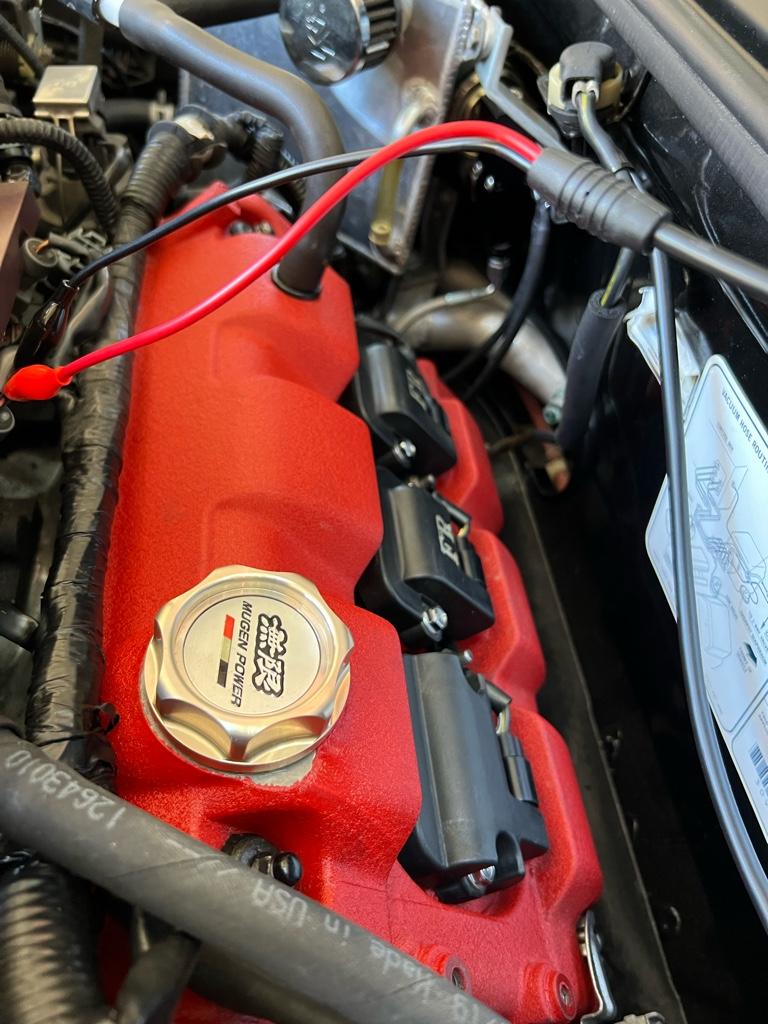
The downside to the new coil is that it was from a Legend. Turns out the legend coils are real fat around the mounting bolt holes. The thicc areas make the coil interfere with the coil cover. I've been driving around with the chubby coil and without the cover for now. Not ideal, but it's fine. You can see the portly coil closest to the camera in the next pic. The wires here going over the chunky-ass coil were from the scope, I was trying work out what the injector signal looks like.
In an effort to have this never happen again, I have spankin new plugs for the rest of the cylinders, all new k-series coils, and the Foundry3 k-series coil wiring kit. I'll be installing all this soon.
Next up is some air temp data. Hope you like looking at a bunch of overlaid line graphs, cause thats what you're getting in the next post.
PPS: if anyone needs a single RC 550 injector (part number PL9-500) I have a brand new one for sale. I never installed it and RC doesn't do returns.
A couple weeks ago I had made some changes to the air temp sensor and I took the car out to test. I barely got out of the neighborhood and it started misfiring. The front bank all of a sudden went crazy lean. Shiiiiiit.
You can see it here, I shift into 3rd and O2 #1 goes lean. Usually the front bank (O2 1: red line) is slightly richer than the rear (O2 2: blue line), but not on this day.
Obviously freaked out, I limped it home. You can see even when lightly cruising the front bank was way leaner (red line) than the rear bank (blue line):
I narrowed it down to cylinder 4 by pulling injector plugs until there was no change. I checked the usual: oil, coolant, and everything looked fine. But I still had prepared for the worst, I dunno, blown ringlands or something. I bought compression and leak down testers. That week there were a lot of searches to figure out how much a rebuild at SoS might be... (spoiler alert: not cheap)
It was running lean, so my thought was that the number 4 injector wasn’t firing. When I messed with the air temp sensor, I had to move around the front bank injector wiring. Did I disrupt a butt connector? Did that injector go bad?
I started this thread asking for help.
On the thread, a couple people mentioned that even no ignition on one cylinder would cause a lean condition. At first this was not so intuitive, but now it makes sense. The idea is that along with all the unburnt fuel coming out, there would also be unburnt oxygen mixing with the exhaust from the other cylinders, and ultimately outweighing the extra fuel: lean reading.
I bought a whole bunch of tools + parts including ingnition-related things based on feedback from that thread. My goal was to fix, or at the very least, understand it the next weekend. I was supposed to take the car to an event the weekend after, so I wanted to solve it as soon as I could.
Fortunately this one had a quick, happy ending. Unlike most things (in life?), the easiest and first thing I tried did the trick. I replaced the number 4 plug and coil. 10 minutes of work and it was totally back to normal. Yay.
It's possible the coil was fine and the plug went bad? I dunno.
The downside to the new coil is that it was from a Legend. Turns out the legend coils are real fat around the mounting bolt holes. The thicc areas make the coil interfere with the coil cover. I've been driving around with the chubby coil and without the cover for now. Not ideal, but it's fine. You can see the portly coil closest to the camera in the next pic. The wires here going over the chunky-ass coil were from the scope, I was trying work out what the injector signal looks like.
In an effort to have this never happen again, I have spankin new plugs for the rest of the cylinders, all new k-series coils, and the Foundry3 k-series coil wiring kit. I'll be installing all this soon.
Next up is some air temp data. Hope you like looking at a bunch of overlaid line graphs, cause thats what you're getting in the next post.
PPS: if anyone needs a single RC 550 injector (part number PL9-500) I have a brand new one for sale. I never installed it and RC doesn't do returns.
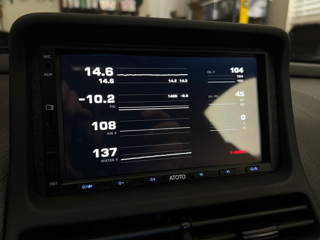
Are you using the GaugeArt setup for this? Also, it's showing 14.6 on the main but also 14.3 & 14.5. I'm assuming the smaller font is front vs. rear and the large be the average of the two? but I reckon the avg should be 14.4?
Are you using the GaugeArt setup for this? Also, it's showing 14.6 on the main but also 14.3 & 14.5. I'm assuming the smaller font is front vs. rear and the large be the average of the two? but I reckon the avg should be 14.4?
It's an android headunit running RealDash, which is displaying CAN bus data. You can read more here. Kind of a production to get the data into the unit. Series 1 serial port -> AEM serial to CAN converter -> CAN bus -> CAN to USB converter.
Yeah the AFR numbers can be confusing. The 2 on the left are the wideband analog outs, through the ECU's O2 pins, out serial, then into CAN. So basically those are the numbers the ECU is seeing. The big top one is front bank AFR, and the smaller one on the left is the rear bank.
The smaller numbers on the right of the chart are from the widebands' digital out (front bank, rear bank). They go from the wideband controllers directly into the CAN bus, then into RealDash. The left numbers and the smaller right numbers are different cause the digital outs are faster by a ms or 2. So likely in the moment after that pic was taken, the big numbers read 14.3 and 14.5. I added the smaller numbers basically as a check to make sure that the ECU and wideband agreed on a reading.
OH dude!!! I am all over this! Just a couple of Q's if you don't mind.It's an android headunit running RealDash, which is displaying CAN bus data. You can read more here. Kind of a production to get the data into the unit. Series 1 serial port -> AEM serial to CAN converter -> CAN bus -> CAN to USB converter.
Yeah the AFR numbers can be confusing. The 2 on the left are the wideband analog outs, through the ECU's O2 pins, out serial, then into CAN. So basically those are the numbers the ECU is seeing. The big top one is front bank AFR, and the smaller one on the left is the rear bank.
The smaller numbers on the right of the chart are from the widebands' digital out (front bank, rear bank). They go from the wideband controllers directly into the CAN bus, then into RealDash. The left numbers and the smaller right numbers are different cause the digital outs are faster by a ms or 2. So likely in the moment after that pic was taken, the big numbers read 14.3 and 14.5. I added the smaller numbers basically as a check to make sure that the ECU and wideband agreed on a reading.
1. I assume this is Android only. As in, I cannot get it to output to a composite video RCA out? I only have an old style touch screen composite video & S-video monitor
2. Is CAN a standard or did you have to load in the definitions for each signal output? Like for example, did the RealDash automatically parse/read the signal from the AEM CAN bus?
btw.. really impressive progress on your thread. I don't have anything to contribute except how wonderful your attention to detail is on your NSX!
Edit: One last question, is your Atoto head unit a full deep double din? I assume not because you were able to fit it into your screen pod. I can't tell from Atoto's site if these are more or less just monitors or otherwise aren't very deep behind the screen. If so, that would be great!
Last edited:
For sure, no problem on the questions. I love talking about this stuff in detail.
1. I assume this is Android only. As in, I cannot get it to output to a composite video RCA out? I only have an old style touch screen composite video & S-video monitor
RealDash is an Android/iOS app, so yeah you'd need something that runs probably Android if you wanted to use the app. Maybe there are headunit controllers out there that dont have a screen, only like component outs? That would be cool. I had to modify the head unit a lot to make it fit in the really shallow space between the navpod and the dash. Tons of pics starting here. Something with the screen being remote might be better...
2. Is CAN a standard or did you have to load in the definitions for each signal output? Like for example, did the RealDash automatically parse/read the signal from the AEM CAN bus?
Yeah, all I needed to do was setup a config file telling RealDash the IDs of the CAN packets I wanted to read, then how to convert the data into human-readable values. Here's my config file. RealDash gets CAN packets via a CAN reader. I use this Seeed studio CAN analyzer.
For context, CAN itself is a standard protocol used in a lot of different applications, it's kinda like car ethernet (or machine ethernet, I guess) if you're semi-familiar with ethernet. It's broadcast: sensors, ecus, whatever emit packets onto the can bus then anything can read the packets floating out there on the bus. The packets each have an ID that represents type of data, e.g. RPM, Speed, etc. CAN is a universal standard used in all modern cars, but the IDs of the packets are different between like OBD-II CAN and AEM CAN. This was confusing for me at first, AEM markets their thing as AEMNet, I thought it was their own special CAN implementation or something. But it's just a regular-ass CAN bus and they use their own ID space so if you plug their sensors into an OBD-II CAN bus, it wont clobber or be confused with data already on the bus. The OBD-II IDs are standardized across all cars these days.
Also, if you're interested in getting something like this going, I'm happy to help with any data / RealDash / config stuff.
Last edited:

It's been pretty hot here in Sonoma county for the last couple months: 90s+ on the regular. For some reason I seem to only get a chance to take the car out at around 2pm during peak heat. I pull the logs off the ECU after pretty much every trip, and I mostly take the same roads, so I have a fair amount of data in a semi-controlled environment with this hot-car summer situation.
After digging through a whole bunch of this data, my conclusion is that Jimmy McMillan is right: the air temps are, indeed, too damn high.
For context, so you don't need to scroll back 5 pages, the car is a 3.0 with an old whipple CTSC + the "high boost" 9 psi pulley, AEM series 1, bigger injectors and all that. The air temp sensor is a Rife Lo-AT open element sensor in the "stock" location over the number 6 cylinder. The car has a water/meth injection system (WMI) with a 500cc nozzle spraying before the throttle body and into the supercharger.
To give you a rough idea of the behavior, on a 90deg F day after it's warmed up, cruising air temps will be around the 130s F. Then they slowly creep up to around 150F after 20 or 30 min of chill driving. If I run an errand and shut off the car for 15+ minutes, after I start it back up cruising temps shoot way up to around the mid 170s. Hot!
Air temps really only matter when it's in boost, of course, but turns out cruising temps are the baseline. Then the temps increase from the baseline in boost. And I've noticed even with the water injection that they can increase 5-25F during a pull, depending on situation.
The ECU starts pulling timing at 158F and by 175F, it's pulling 2 whole-ass degrees. This has a huge impact on performance. The car feels crazy quick on a cooler day with the baseline cruising temps under 120 or 130, and really slow after I've let it sit in some parking lot on a hot day for a half hour and it's working with a 175F baseline.
It feels dangerous to mess with the air temp / timing table, so my effort has been tweaking things in an attempt to get the temps down. I have water injection after all, this should be a solved problem, eh?
Insulating the Air temp sensor
The first question I was trying to answer was: is the temp sensor heat soaked? Like are temps actually lower than they are reading because the body of the sensor is hot?
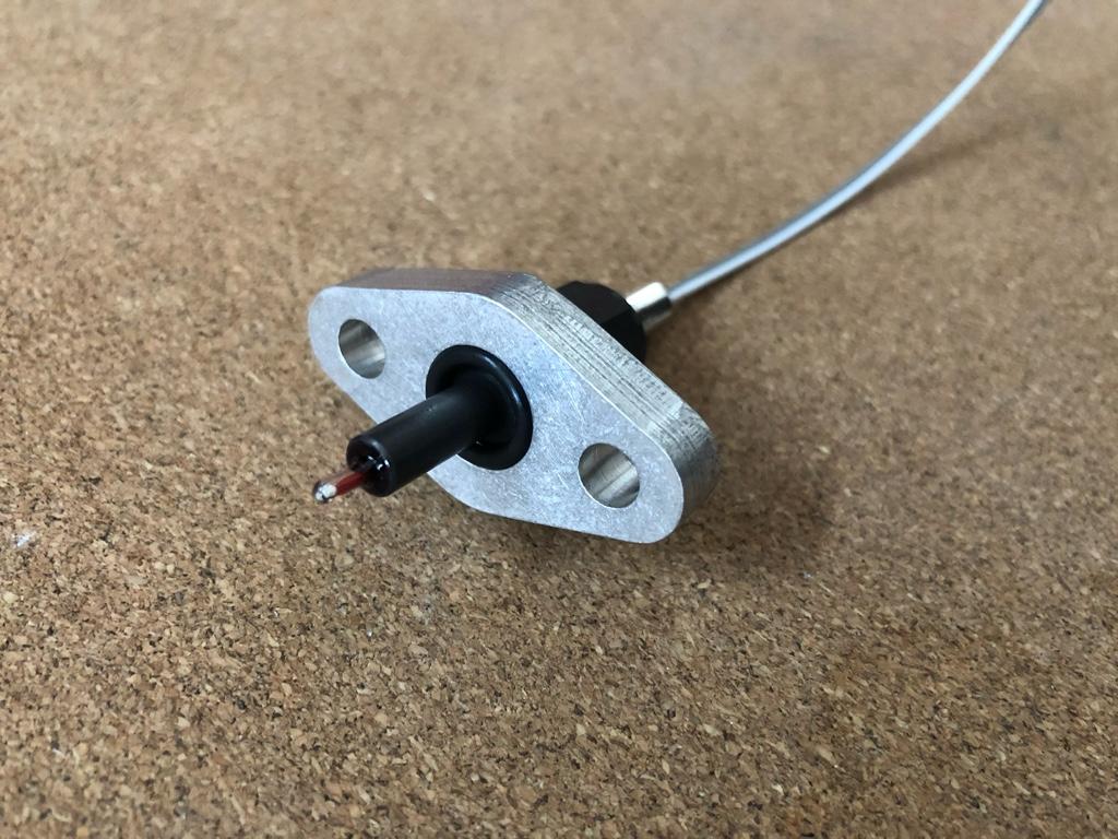
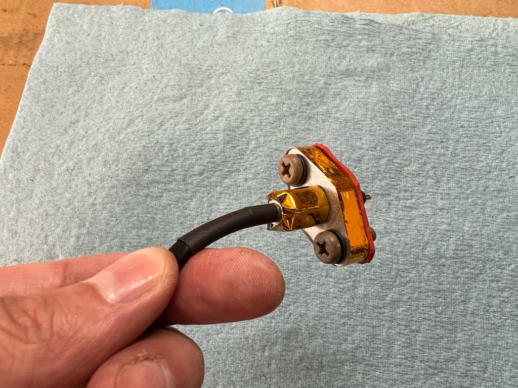
This is a common internet complaint/maybe-problem in forums across the land. Open-element sensors like my Rife unit are supposedly less prone to it, but who knows. The sensor has an aluminum body and is mounted to an aluminum manifold with an aluminum flange. Heat transfer city. I mean, maybe? Here's the sensor in the aluminum on aluminum on aluminum configuration:
Also it bothered me that temps are way high (175F say) after parking the car and starting it back up, and they don't come back down unless I do a few pulls to trigger the WMI. Maybe signs of sensor heat soak?
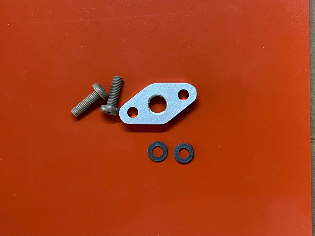
I was going to send an expensive piece of PEI plastic to my dad so he could fashion it into a new insulating flange on the mill to replace my aluminum one. He was like, um, use a gasket? Turns out a gasket was faster and easier.
I got a 1/16" piece of silicone gasket material, and some PEEK plastic bolts so the bolts wouldn't transfer heat.
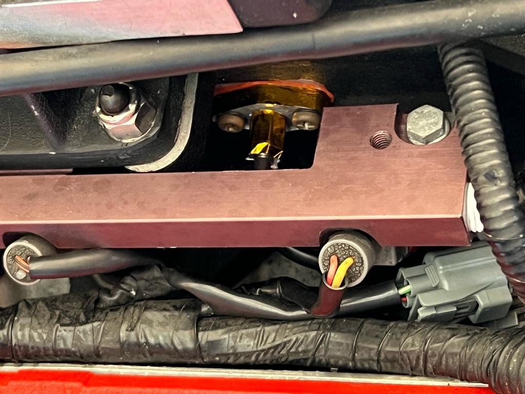
I also wrapped parts of the sensor and flange in heat shielding. Here it is with its tinfoil hat:
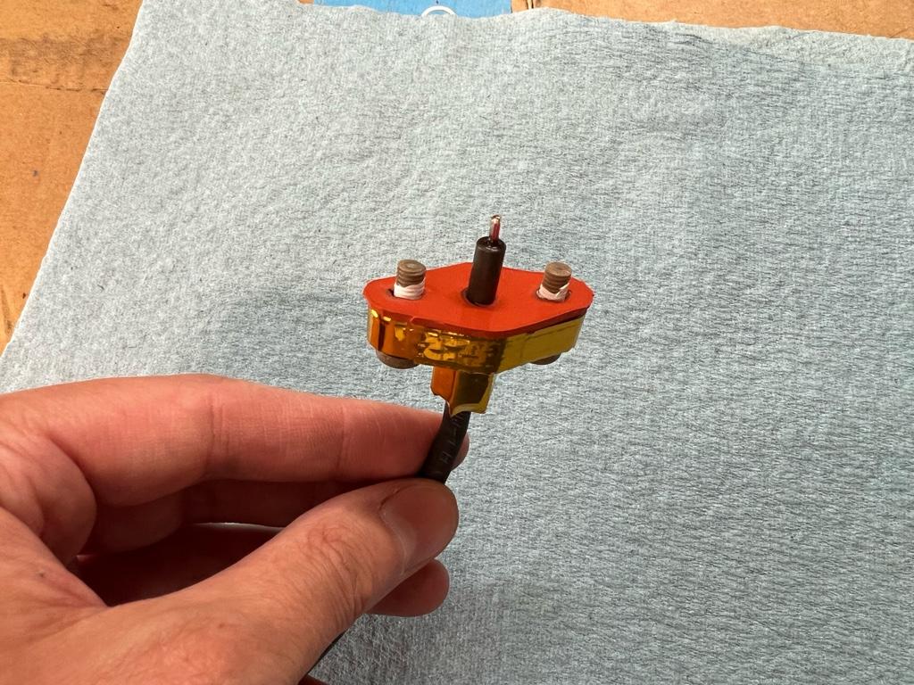
Then installed in the car. I'll definitely be able to rule out alien mind control:
Ok sweet, well did it help?
No. Not in any meaningful way. It's possible there was a small change where it reacts faster to temp changes, but it's tough to tell. After sitting on a hot day, the cruising air temps will still be in the 170s.
I suppose supercharger and/or manifold heatsoak is probably the main issue. If that's the case, it's surprising to me that the air heats so much so quickly just by passing through the hot SC. Is what it is though.
I'm considering getting one of those phenolic plates between the manifold and SC as another attempt to improve this, but worried about fitment as it will move a whole lot of parts up by 1/2". Also seems like a production to pull the supercharger off the motor. Maybe I should just bite the bullet there and put the water nozzle in it too.
Hot behavior
After looking at a ton of data, the tl;dr is that the WMI does have a huge impact on controlling temps, but needs to be spraying pretty consistently to keep them in check. This gives me confidence things will be ok on a track, but it's annoying on the street where there are long stretches of no-boost.
Here is a typical scenario. This day was probably 95deg ambient and I had stopped then started the car several times. I had it in a couple full sun parking lots, then started it up, idled through a small town, and got on the freeway at WOT:
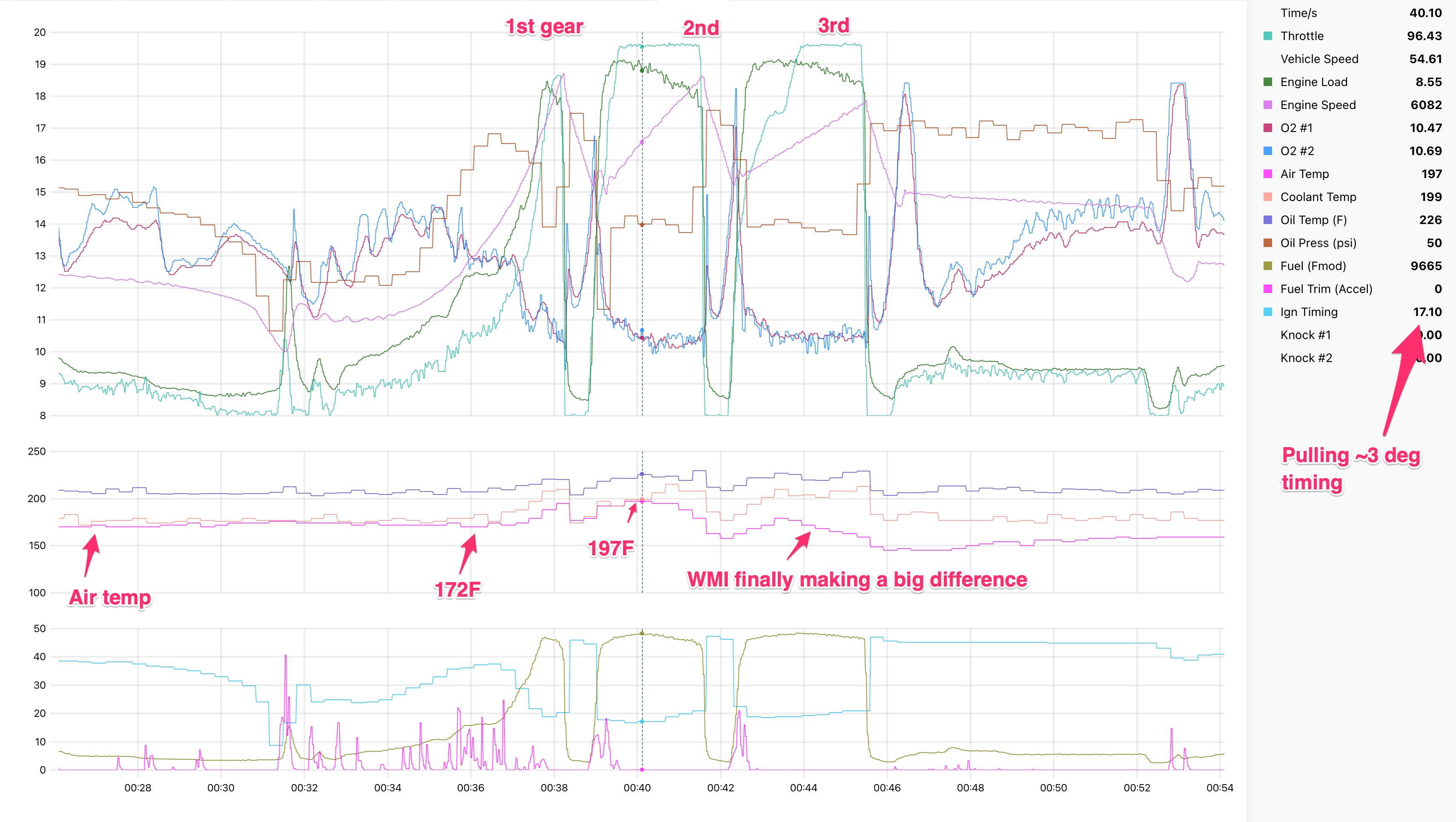
Even when it's spraying, and even after a short 1st gear jaunt, there was a 25F jump over cruise temp in second gear, obviously pulling a mile of timing. Halfway through 3rd gear, the WMI is doing the deed: literally dropping temps in boost. Win, kind of. You can see the timing slowly increasing (cyan line in the bottom chart) to the uncorrected ignition map value (~20 deg at 9-10 psi ~21 deg at 7-8 psi) as the air temp drops.
My initial expectation of the WMI was that it would behave like 3rd gear from that chart every gear, every time it was spraying. But nope. This is probably at least partly a function of my nozzle placement. I just imagine the water absorbing heat from all kinds of garbage on the way in--the TB, SC rotors, SC housing, intake manifold--until it's all used up and can't heavily cool the compressed air. Then at some point those parts are cool enough where it can start making an impact.
Another thing to note from that chart is that things are a bit richer than they should be: mid-low 10s. I was experimenting with ~25% methanol on this day. Well, looks like it affects the AFR quite a bit. Even at 25%, AFRs read 1/2 point richer. Also doesn't help that the timing is pulled. You can see the AFRs lean out a tiny bit as the temps drop and it adds timing in 3rd gear...
Primed behavior
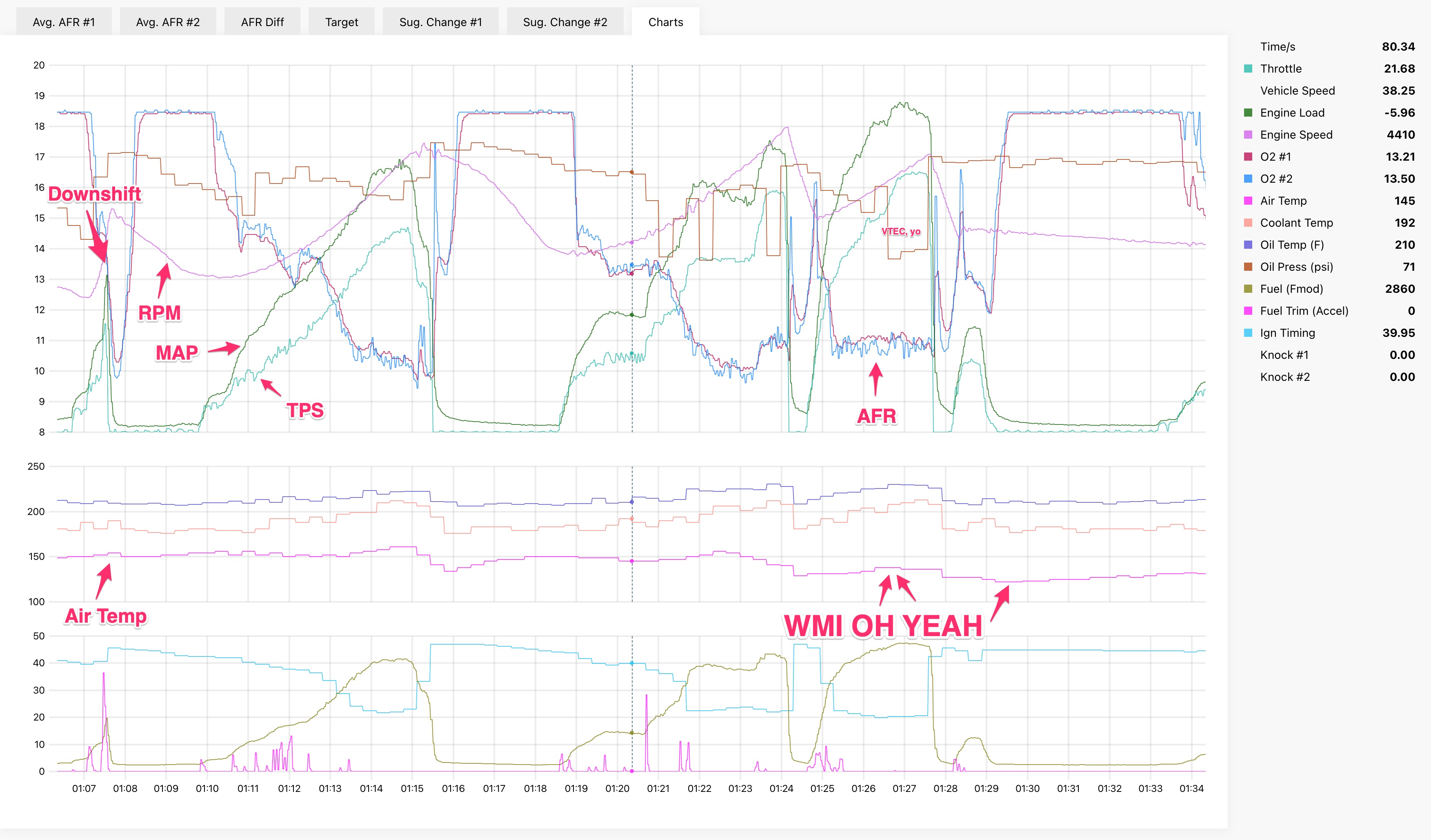
After a few pulls, things kind of stabilize and temp jumps in boost are less dramatic. I have been thinking of this as a sort of "primed" state. Here is a 1-2 + just the tip in 3rd on the same day and same trip. About 45 seconds before this set, I went WOT in 2nd gear which put the cruising temp at around 150F.
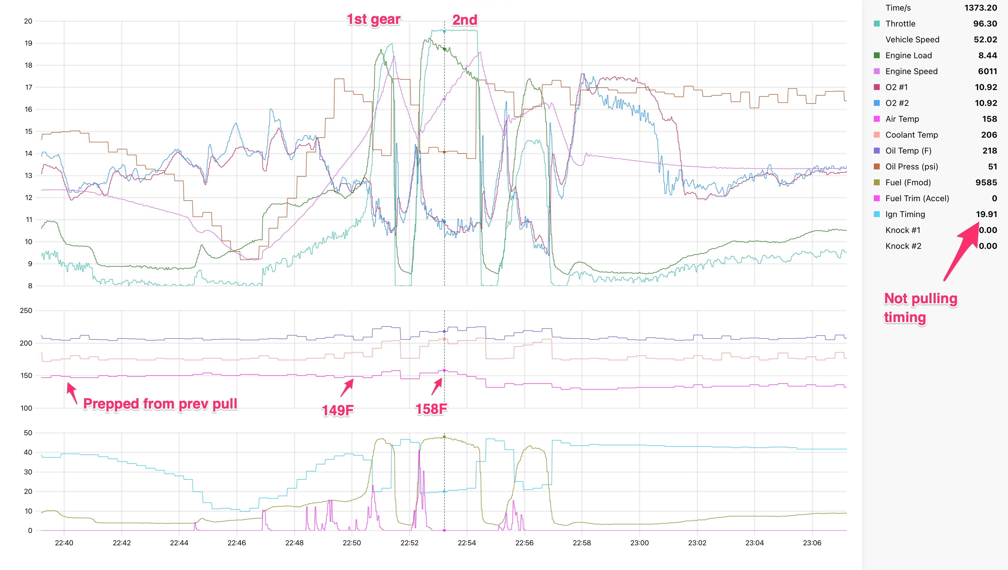
Better, eh? Only a 9F delta and the temp starts decreasing while still in boost. No timing being pulled, the car is faster, yay. The time scales are the same between the two above charts. You can see that the 1st and 2nd gear RPM lines are literally steeper in the second chart. Steeper = quicker.
Real-ish world behavior
Turns out when I take it out for a romp in the woods, I'm actually rarely WOT, and not even in boost all that much. I tend to drive it like it's got no power on my fav roads, which makes keeping the temps in check even more challenging.
I've been experimenting with having the WMI start spraying before it's in boost. It's annoyingly non-scientific as I can't log the dumb WMI controller, and the knobs on the controller are super imprecise. So I'm going off a combination of the always-half-on-anyway LED, and the weird little whine it makes when it starts spraying. I have it starting to spray where the knob says ~7% injector duty. Looking at the fuel maps, this is impossibly low, but based on trial and error it seems to be right about pre-boost at ~4k rpm. Most of the cooling effect still happens in boost, but I'm just trying to keep it primed and the deltas low.
Here's a section from my fav chicane which is more representative of a spirited street drive; half throttle action, low boost, but still cooling things down:
I took the car to an autox a few weeks ago where we got like 30 runs. The early-on + early-full-power WMI settings ended up being kind of a problem. I was almost entirely out of water in about 10 or 12 runs. I guess there'll have to be street and "track" settings to get good cooling but also still have water in the tank. I’m also bringing like 5 gallons of extra water next time. It definitely would not have lasted a full 20 min track session. More on that in the next post...
Last edited:
I figured out the CTSC heatsoak issue about 5+yrs ago. I know all too well there issues you're experiencing. The key for me was to spray after the SC and directly into the intake manifold. You end up using a shit ton less WM and you tank will last longer and not flood your fuel with WM as well as not coat your SC twin screws with potentially harsh methanol.
I made this video years ago. Can't exactly remember the details of what I talked about but I think I cover all your concerns.
https://youtu.be/pey4tGDZ8gc
I made this video years ago. Can't exactly remember the details of what I talked about but I think I cover all your concerns.
https://youtu.be/pey4tGDZ8gc
Thanks, I watched the video! I definitely have read your past posts about the AS phenolic plate. I think it’s probably what I’ll end up with, I have had a browser tab open to that thing for like a month now lol.
My main concern with it, outside of the effort to install, is the extra height of the sc and the tb. You said in the video it was like an inch and a half tall (maybe I misheard)! Like does it cause issues elsewhere? The old whipple has a pipe off the snout that routes down into / under the intake manifold. Does that still line up with whatever it’s connected to down there? I suppose AS has probably solved any issues there.
I didn’t realize your air temps were so low (90-110max) with that setup. I thought they were in the 130 range for some reason.
I want to say it was less than 1" in total height. Probably somewhere between 20-25mm. TBH it's probably thicker than it needs to be but it's supporting the stress of the belt tension and the weight of the blower so Adnan and I wanted to make sure it was beefy enough. Dude.. this setup on my car was bulletproof. I'm just a glutton for punishment when I took it off and endeavored into a new build path.Thanks, I watched the video! I definitely have read your past posts about the AS phenolic plate. I think it’s probably what I’ll end up with, I have had a browser tab open to that thing for like a month now lol.
My main concern with it, outside of the effort to install, is the extra height of the sc and the tb. You said in the video it was like an inch and a half tall (maybe I misheard)! Like does it cause issues elsewhere? The old whipple has a pipe off the snout that routes down into / under the intake manifold. Does that still line up with whatever it’s connected to down there? I suppose AS has probably solved any issues there.
I didn’t realize your air temps were so low (90-110max) with that setup. I thought they were in the 130 range for some reason.
I had no issues with the added height. It cleared everything and there was enough flex in the intake pipe to still allow for the factory airbox placement. I mean it's not super optimal but so many years of hard driving and it was absolutely bulletproof in my NSX. You will have issues if you're still using the factory engine cover (I removed mine) and Targas need to modify the triangle bar. Given the new set of challenges i'm facing now, in some ways I still think I should have never touched it lol
EDIT: just to add... the elegance of this solution is really it's efficiency. I just kept decreasing the size of the nozzle until I could find the smallest one possible and then I still turned down the output of the pump. Night and day difference between spraying before the SC. An entire 1 gallon tank would last me at least 2-3 full fill-ups of gas under spiritied driving. At the track i'd get at least 2 sessions out of 1 tank. In the winter it sometimes even overcools the IAT but you've got an ECU to handle that part of the tuning. If I knew @MotorMouth93 back then I might have worked with him in a plug and play solution for the WMI on the stock ECU and the stock CTSC setup.
Last edited:
I want to find a CTSC to borrow and try to tune lol. It would be pretty easy to repurpose something like the VVIS control output (or even EGR PWM for variable spray) and have it based on a map vs rpm table or something like that.
Noted on the plate. Definitely sounds like the dream. I really want low air temps on demand. Having to have it sort of primed and using so much is not ideal. I’d love to be able to spray a little meth and get the octane boost but not have it hugely affect the AFR.
I emailed AS Motorsport about it and asked a bunch of questions. We’ll see if he’s down to make one for me
Man I really want a fully ecu controlled solution. The data alongside the rest of the engine data, plus the ability to precisely set it up would be amazing. When I eventually move to a haltech I’ll make an attempt to have it run the system in a nice way. Though I still haven’t seen anyone with a simple ecu-only setup. The pump requires a lot of current. So it’d probably be a PWM out to the dumb AEM box.
I emailed AS Motorsport about it and asked a bunch of questions. We’ll see if he’s down to make one for me
I want to find a CTSC to borrow and try to tune lol. It would be pretty easy to repurpose something like the VVIS control output (or even EGR PWM for variable spray) and have it based on a map vs rpm table or something like that.
Man I really want a fully ecu controlled solution. The data alongside the rest of the engine data, plus the ability to precisely set it up would be amazing. When I eventually move to a haltech I’ll make an attempt to have it run the system in a nice way. Though I still haven’t seen anyone with a simple ecu-only setup. The pump requires a lot of current. So it’d probably be a PWM out to the dumb AEM box.
Similar threads
- Locked
- Replies
- 4
- Views
- 398