• Protip: Profile posts are public! Use Conversations to message other members privately. Everyone can see the content of a profile post.

bogle's 1991 mild build thread

Thanks! Glad it’s interesting and possibly useful.

I feel you on build threads. I also find myself just wanting to know like what state a build thread car is in now without having to go through 20 pages of stuff. But also like seeing other people’s path through their car. I’ve used so much from other build threads on prime.

That reminds me that I need to write a couple updates. Lots of little stuff, troubleshooting, and gathering parts for a couple big projects lately….
 
Update time!

About 2 months ago I upgraded the ECU .... to another AEM series 1. I had been on a super early AEM series 1 ECU (part number 30-1006) and it had some quirks. The biggest pain point was electrical noise on some of the sensors, namely TPS. But it also didn't expose all the open 0-5v input channels which was unfortunate. I wanted to send fuel pressure into the ECU and maybe couple other sensors, but the OG unit didn't have enough inputs.

@MotorMouth93 had a later model series 1 (part number 30-1042) he wasn't sure he was going to use. I asked if he'd sell it to me and he obliged. Thanks yo!

Installed. It's much smaller than the OG unit, looks like the series 2 form factor:

fp-ecu.jpg

Yeah that's a wood block. SEMA '23 ain't ready for my attention to detail.

I bought this thing from him a pretty long time ago and just sat on it. I did try it in the car immediately when I got it, but couldn't get it running. I loaded up my cal file from the older unit and tried to start it, but the fuel pump wouldn't turn on.

John (MotorMouth93) found a little note in the AEM docs saying that the older unit's cal files wouldn't work in the newer unit. Good to know. He sent me the original cal file out of this new unit and I transferred all the settings over from my old file to his new one, menu by menu, table by table. It took a while, but it gave me something to do on a long haul flight. "What are you doing?!" My girlfriend asked several times. "Why don't you watch a movie?" Like I was being forced into this monotony.

With my settings in the newer cal file it fired right up, but surprisingly ran pretty different. So I tuned idle again for the 50th time, and took it out. In my transfer I missed a couple tables, notably the "Boost fuel correct table". It'd get into boost, go crazy rich and feel like a fuel cut. Oops. It took a couple passes to sort everything out.

After some effort, WOT showed the same AFRs as before, but the cruising bits of the map were .5 - 1 point richer. OMG why? I don't know. I did a lot of tinkering but couldn't find a legit reason. The output pulse widths were the same, but it was just a little richer in vacuum. Whatever, I decided just to tune it out of the fuel map. It's possible there is something different in the ECU electronics or some setting I just haven't found. It seems mostly impacted at really small pulsewidths. Injector driver differences? No idea.

Sensor noise

After the car was running pretty reasonably, the big question was: is this new ECU less noisy? If you've been following along, you know that the TPS signal was noisy, fluctuating between 3 and 5% while cruising. This caused some pain while tuning tip in

I'm happy to report it is significantly less noisy.

The old ecu:

208248564-37fc7dc1-0368-41c1-913a-617aa2c57a6c.jpg


The new one:

208248563-7ff454ac-156e-49ae-a221-dcf4efcd5f64.jpg


Sweet! I did some accel / tip-in tuning and was able to lower the threshold quite a bit. Tip in feels a good bit crisper now than with the old series 1. Cool, yay, progress.

Fuel pressure

The other big feature of the newer series 1 was that it exposed several more sensor inputs. I had a fuel pressure gauge in the car and wanted to get that data into the ECU. I had no idea how fuel pressure moved under load, I was not about to look down at the shifter area while in boost.

The plan was to use the EGR lift connector and signal pathway. This pathway is 3 wire: it already gets 5v and sensor ground, which is exactly what a pressure sensor needs. I'm going to remove all the EGR junk anyway (the ECU doesn't use it) and the EGR plug is pretty close to the fuel filter, so this all made a lot of sense. I made a patch harness and was going to use a lowdoller 0-100psi sensor:

fp-sensor.jpg

Plugged in for a test here. I ultimately threaded it behind the injectors and it looks kinda factory.

fp-wiring.jpg

On the sensor side. I ended up using the AEM gauge's sensor just cause it was already there. Turns out most (all?) 0-100psi NPT fluid pressure sensors are all the same form factor, plug config, and output voltage scale. AEM and the like probably buy the sensors from the same place and rebrand them.

fp-pluggedin.jpg

Into the ECU the electrons go, it spits them out onto the CAN bus as raw ADC, then into the navpod. Here's the fuel pressure in the middle chart on the right while the car is warming up:

fp-navpod.jpg

It's pretty cool to be able to see fuel pressure in the logs now. It's around 46 psi at idle (10psi vacuum), then peaks at 60-62psi (9.5psi boost)

Note the voltage charts on the bottom right of the navpod. A sign of the nonsense rabbit hole to come....
 
Voltage drop rabbit hole

Waay back in September I installed k-series coils to replace the stockers. Setting coil dwell in the ECU was not straightforward and required a lot of trial & error: do some logging, change some settings. The coil dwell tables are based on ECU voltage, so I logged the internal ECU voltage just to see the behavior. Logging voltage was kind of theater, curiosity; I expected it to be pretty consistent somewhere around 14v.

But it wasn't consistently 14v. The logs showed that it hovered around 13.8v (gauge in the car said 14.2v) while cruising and had a pretty significant voltage drop in boost. It'd get down to ~12.5v, check it out:

voltage-drop-jpg.175527


Annoying. Nothing was really wrong, but maybe it was indicative of something larger? In any case, it felt wrong and I figured I could fix it.

I posted a thread asking for help, so you can see the whole discovery process there. But I'll summarize in this post.

This was a 6 week wild goose chase and I'm back to where I started, except now I don't feel comfortable driving the car for reasons I'll get into later. It'll be fine once I fix some stuff, but it's a garage queen for the next couple months. Derp.

What is problem?

I thought the voltage drop was probably caused by the alternator. Because of the CTSC, the car uses a 92 prelude alternator which is only 90A. My hypothesis was that the WMI, fuel pump, and maybe coils had huge current draw at high RPM, but the alternator couldn't keep up. Or there was alternator belt slip.

I should have done more tests before coming to that conclusion, buuuut I didn't. No downsides, I thought. A high output alternator could only be better, right? Might as well just buy one and see....

HO alternator

I needed a 92 prelude alternator. The 92-96 prelude isn't a popular tuner car, so these things were pretty hard to find. The car audio world has a lot of experience with upgraded alternators, and those guys trust only 2 or 3 alternator brands. The most promising for me were Mechman and Singer. Mechman never got back to me, but the Singer guy did.

Singer was convinced that the 97+ prelude alternator was the same form factor as the 92-96. He's the expert, right? He built one and sent it. Welll, the 97+ alternator was totally different in every way, 6 rib, smaller pulley, much larger case, mounting points didn't line up, different plug, etc. He tried to convince me to modify it to fit, but no thanks.

I sent it back and he built one with a 92 prelude case. Because it is smaller, I guess there are some limitations on how it can be modified. I dunno, but here it is:

alt-new.jpg

One immediate downside was that it came with a smaller pulley:

alt-pulleys.jpg

Maybe it was fine though. I got a smaller belt and installed it:

alt-installed.jpg

Did the new alternator fix it?

No. In fact, several other things were worse. Immediately on startup it was super noisy, like a bad bearing howl. Okay, but maybe the voltage drop was better?

Also no. With the belt pretty tight (no boost fade) and under load, the battery light would come on and the voltage drop was still there. Not ideal. I tightened the belt more, but still battery light flicker in boost.

I figured the pulley was too small. Either it doesn't have enough leverage at a reasonable belt tension, or it's spinning too fast. Apparently the RPM limit for an alternator is like 16-18k RPM, after that they stop charging. I did some math and with the small pulley, it'd be 20k+ at 8k engine RPM. With the stock pulley it'd be under 16k RPM at 8k engine RPM.

I put the larger stock pulley on the HO alternator, and tried again. Battery light gone, but the voltage drop in boost was still there, behavior looked exactly the same. Dumb.

Even though there was no more battery light, there were more problems with the HO alt + larger pulley. It wouldn't hold voltage at idle, and it couldn't deal at all with any accessories. 12.5v at idle here (12.8v at the gauge):

211173339-d92861d8-f95f-42fc-bb5d-ec7634cceace.png


Allllso, on RPM changes, there were voltage spikes not present with the denso alt. It was more pronounced at idle, but still would spike to ~15v on the gauge while cruising and stabbing the throttle. Here it is at idle. This log says the spike is 14.6v, but through this process, I learned that the ECU consistently reads 0.3v lower than the gauges, so this is just under 15v, and I definitely saw > 15v on the gauge:

211173342-dccdbabf-4b0a-422b-ba1f-bba151dee716.png


Ultimately I went back to the stock prelude alternator. With the HO alt, I'd need to deal with either a battery light or no voltage at idle. Plus it had consistent bearing noise at idle and electric whine at 3k+, and ran waaay hotter than the denso alt. All no bueno, and the drop issue wasn't fixed anyway.

Testing

Throughout my diagnosis thread, Old Guy was crazy helpful in trying to track this down. The goal of the testing was to figure out exactly where the drop was. Was it in the ECU? The whole car? The ECU / injector circuit? This is the work I should have done in the first place, instead of buying the alternator.

I added a CAN bus expansion module which also output voltage. The module is run off the ECU power pins, so exact same circuit/voltage the ECU is getting

vdrop-can-volts-jpg.175695


Installing this was its own saga. The AEM docs had the addresses wrong for some of the CAN messages, so it took a lot of trial and error to get the right data. But it worked, here it is in the navpod (bottom right):

vdrop-navpod-jpg.175696


I took it out with the gopro pointed at the dash and 4 (5?) different volt meters:

1. A voltage gauge on the IGN circuit (round gauge)
2. A battery meter on the battery terminals (on the phone)
3. ECU logged voltage (navpod right, 2nd from bottom)
4. New CAN voltage (navpod right, bottom)
5. Battery light

At idle, they all pretty much agree, except for the ECU-reported volts, which is always ~0.3v lower. Then during a pull it showed this:

voltage-drop-2a-jpg.175697


What does it all mean?! The conclusion was that things are probably fine.

The pic indicates that the drop is in the ECU voltage circuit, which is the same circuit driving the injectors. At high RPM in boost at 40-50% injector duty cycle, there are probably 3 injectors (8 - 9 ohms, 1 - 1.5A each) open at once which causes a voltage drop in that circuit. The voltage drop only really affects the opening of those injectors, which is compensated in the ECU.

That was kind of The End. Whomp whomp. Several weeks of trying stuff and installing the alternator 10 times with no real resolution.

I guess the drop is fine and maybe even normal. Old Guy thought maybe there was similar behavior in a stock car as well.

I broke stuff

Other than some cleaner grounds and a new gauge in the navpod, I'm mostly back to where I started: on the denso prelude alternator, and still with a voltage drop.

During this whole process, one potential problem was belt slippage at the alternator. How do you solve that? A tighter belt? Belt tension on the SC / alt is known to be art: tighten until you can't twist the belt in a certain place past 90 degrees, then it's tight enough.

For a couple drives I had it pretty tight, but I could still twist it only 90 degrees. In one of these drives I noticed the air temps were super high, even when cruising.

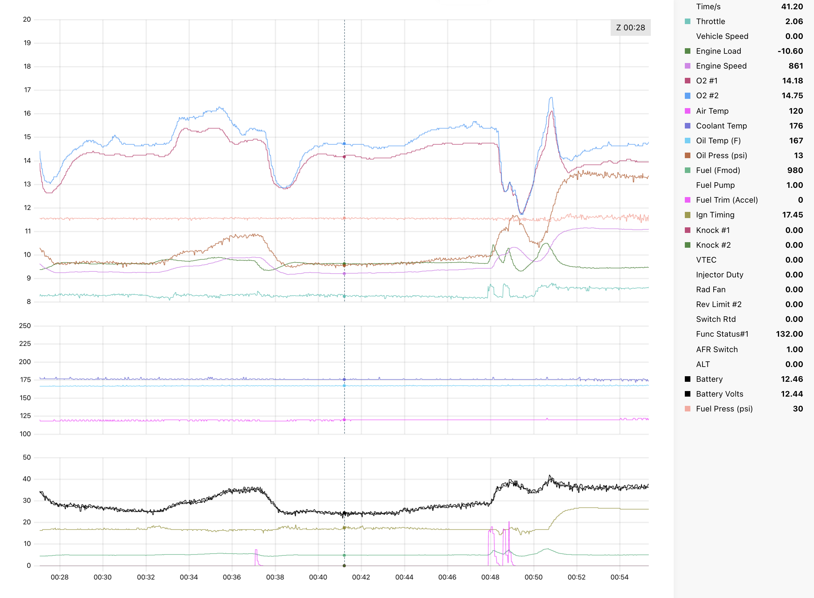
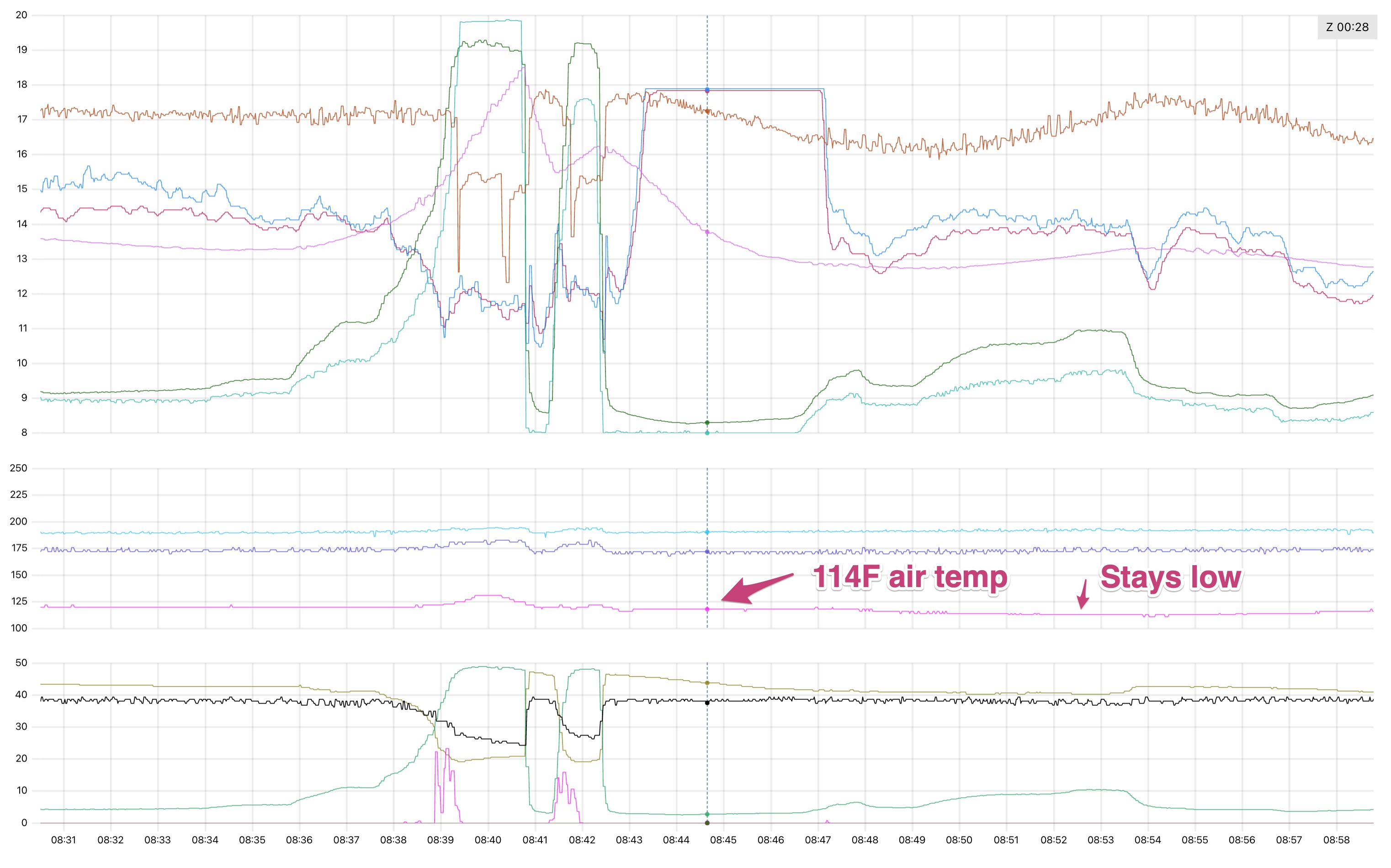
Before tightening the belt, the air temps would usually be pretty low when cruising. During a pull, the WMI would kick in, then after, the air temps would settle lower than the pre-pull temps. These logs were taken in November where the ambient was ~60 degrees f, which usually gives ~110-120f cruising air temps. This is normal:

211174734-022be2c7-c476-4d4e-8585-41e5de33b08c.jpg


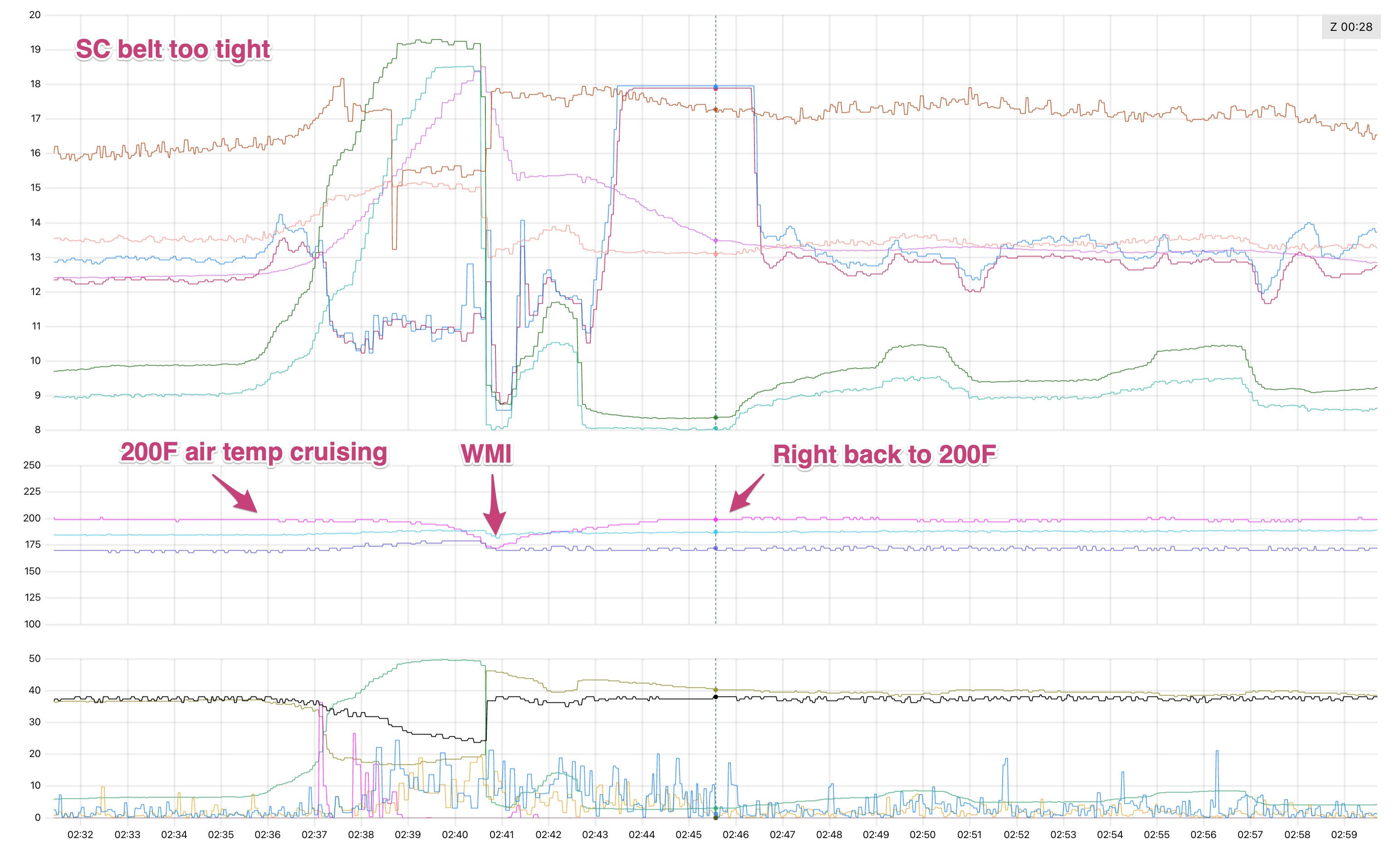
But with a super tight belt, air temps were HIGH, and they were high all the time.

211174736-85d88c32-c4d9-4393-b2a3-1b2e454475c2.jpg


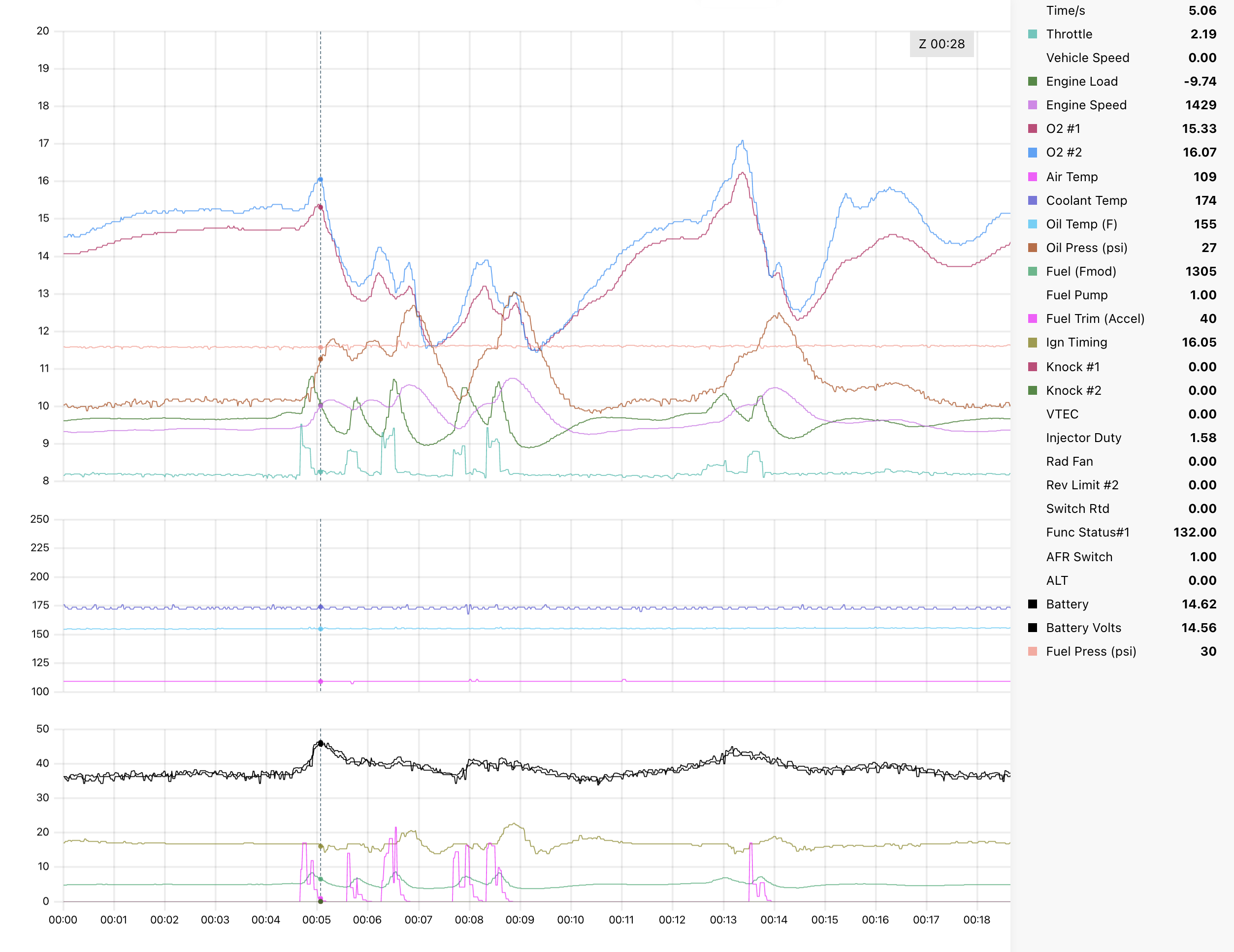
I've never seen air temps this high, and it seemed to coincide with RPM, even when cruising. At 3k rpm: 200f, pull up to a stop light, they'd drop to 180f. Not good.

Loosen the belt, and things go back to normal, right? Right?!

No, ugh. I have since loosened the belt significantly to where there is a lot of boost fade. The air temps are still really high, they creep up pretty quickly after a cold start, and still the same pattern. I used the temp gun on the SC after a few of these drives and the snout + gear case was HOT: 175-180f, same as air temps at idle.

SC needs a rebuild

Well, I likely damaged something in the SC snout or gear case by overtightening the belt. I called Jon Bond performance (supercharger rebuild people) and asked about this, they said they see bearing damage causing heat from overtightening all the time. It's nothing catastrophic, but probably needs a rebuild. I have one scheduled with Jon Bond for early March.

The upside is that during the rebuild, they will also inspect everything else, replace all the bearings, ceramic coat the rotors, powdercoat the rotor case, and ceramic coat the snout. So it should be brand new when I get it back. The guy on the phone said people often see a noticeable efficiency increase after a rebuild because of the fresh rotor tolerances.

I also have a phenolic sandwich plate that goes under the blower, so I was planning on pulling the SC and intake manifold anyway. Fate, I guess.

phenolic-plate.jpg

I now have a belt tension gauge and a bunch of boost fade data at different tensions (both hot and cold tension). When I get the SC back from rebuild, I'll creep up on tension until there is minimal boost fade. I definitely don't want to mess this up again.
 
Jack stands crew

The car is officially down for a couple months. I've started tearing things down because 1️⃣ I probably messed up something in the supercharger by overtightening the belt, and 2️⃣ while it's down and the SC is off I can tick a couple big things off the list. The supercharger will soon be off to Jon Bond performance for a rebuild, and I'll have tons of access to junk I want to replace.

In the last year or so, two main things on the car have stressed me out: air temps and water temps. To be fair, water temps aren't really a problem, but I'm not confident the car can be driven for long periods of time in moderate anger without quickly becoming a problem. Air temps are better with the WMI, but they are super inconsistent because of heat soak: I park the car, start it back up, air temps are sky high and timing is pulled. Basically the supercharger itself is about at engine temp and significantly heats the air.

The goal is to improve both in this pass.

Air temps: I'm adding that phenolic insulating plate (pic in last post!) between the supercharger and intake manifold. The water / meth nozzle will be moved into the plate and will spray right into the output of the supercharger instead of before the throttle body. It's also possible the supercharger rebuild makes things more efficient. The guy I talked to on the phone at Jon Bond said re-coating the rotors can improve temps and flow.

Water temps: I'll be putting in a Masiv radiator and finally doing all the hoses, sensors, and thermostat. A few of the hoses should be a lot easier with the intake manifold out of the way.

As usual, since I have stuff apart, I'll be replacing and cleaning a billion things. The IACV is nasty, the intake manifold needs a shower, I have new bolts, nuts, brackets, vacuum related stuff, knock sensors, etc.

Coming apart

Well here it is in progress. There was a lot of stuff to disconnect. I had dreams of pulling the supercharger off without pulling the intake manifold. Like most dreams, it turned out to be nonsense.

sc-in-progress.jpg

I don't like fuel everywhere so I got these AN plugs. I ended up getting caps too for the fuel rails, but not shown here

sc-fuel-plug.jpg

The intake manifold is held on by 4 nuts and 4 bolts. Seven of them were easy, but this bolt was not. I just couldn't get anything on it.

sc-hard-bolt.jpg

I had absolutely everything disconnected, but couldn't get this bolt loose, and had to leave it for a week while I waited for a bunch of weird 12mm socket-y things to arrive.

In the end I got the whole thing off as a unit:

sc-whole-thing-off.jpg

And the whole thing upside down:

sc-whole-thing1.jpg

The grey wire here has been an unknown thing zip tied to the throttle cable since I've owned the car. Now I know WTF it is: a pressure sensor. I assume they used this on the dyno or something. Maybe I'll put another one there and run it into the extra CAN bus unit + have something they can tap into on the dyno.

sc-whole-thing2.jpg

Both pulling the intake snout off the blower and getting the blower off the intake manifold we're pain. Whoever installed them used a whole bunch of Hondabond. I spent a lot of time staring at it, trying different pry points. I found a couple places I could wedge a dull screwdriver without damaging any surfaces.

This screwdriver here is separating the blower from the manifold. It's resting on a drain plug in the SC and a painted surface of the manifold. A bit of tapping on the screwdriver broke it free from the grips of the Hondabond:

sc-separate.jpg

And separated. No gasket, just Hondabond, derp.

sc-separated.jpg

I removed a bunch of stuff from the manifold. Jon bond wants to inspect the diaphragm too, so it had to come off:

sc-manifold-apart.jpg
 
Supercharger pics

A couple sc pics. (The plastic wrap on the snout is to keep the oil from dripping out of the breather bolt)

sc-unit.jpg

The inlet. I had no idea what this looked like before pulling off the intake snout:

sc-inlet.jpg

And the outlet. You can see despite spraying water and sometimes methanol into it, the coating is still there!

sc-rotors.jpg
 
Coolant hoses & radiator

Big job complete: all coolant hoses. Yay! Having the car down and everything apart for the SC rebuild gave me a good opportunity to do the hoses. At 135k miles, they needed to be replaced.

Pile o' hoses:

hose-new.jpg

And here's most of the old ones:

hose-before.jpg

The job was extremely time consuming. I have the better part of four days in it, and I still haven't dealt with the fill and bleed. I was moving kind of slow, though. It's a messy job, but I tried to avoid a huge mess. I also spent a lot of time cleaning parts and looking around for dirty parts I could add to my next giant amayama order.

It ended up being a few discrete jobs:

1. Drain and remove parts: 2 hours
2. Tunnel hoses: 3 hours
3. Engine bay hoses: 6 hours
4. Underhood / frunk hoses: 6 hours
5. Oil cooler hoses: 4 hours
6. Fill & bleed: ?? hours

Tools

For me, a lot of time was consumed fighting with clamps. If you're reading this and haven't done the hoses yet, one piece of advice: make sure you have a big variety of pliers. Here's what I used and it was still pretty slow:

hose-tools.jpg

For the big hoses, the channel locks (blue handle) were super key. I used the round hose needle nose pliers there mostly for clamps, not for pulling off hoses!

One thing I wished I had was long needle nose pliers with an angled tip. Also a long set with a wider grip (non needle) would have been nice.

A couple other key tools

* Oil spill mats
* Utility knife with new blade
* 3/16" ID silicone hose for the bleeders + block drains
* Silicone lube spray
* 5 gallon bucket for spent coolant
* Oil drain pan for coolant
* Small plastic take out container to put under hoses for spillage

Tunnel hoses

After draining, I did the tunnel hoses first. Here they are finished:

hose-tunnel.jpg

There are 3 of them in there and they are all packed together tightly.

After draining, the 2 large lower hoses were pretty dry: no surprise coolant in the face.

However, the smaller heater hose up top still had coolant in it! I opened up the knife slice just enough to let it drain out into the pan before taking the hose off.

Since these were the first ones, I was learning how to cut them off with the utility knife. The technique is to just cut through all the webbing in the middle of the hose with the knife. You can feel each of the little strings in the knife as you cut through them. I'd go a little deeper with the knife to make sure I was through all the webbing, then use a dull screwdriver to open up the slice.
 
Coolant hoses: engine bay

Next step was the engine bay. Where I started:

hose-engne-start.jpg

The coolant tank off:

hose-engine-no-tank.jpg

Then all the big hoses off:

hose-engine-off.jpg

Here I was trying to be super careful not to mar up the hose barbs, what a sucker! Those before me were not so careful. Looks like someone used a screwdriver on these. No leaking though...

hose-engine-nipple-screwdriver.jpg

Also there was a lot of rust on the nipples on the thermostat block. This was the worst one:

hose-engine-rust.jpg

I spent a fair amount of time trying to figure out what to do about the rusty nipple. I considered buying a whole new block, but it was expensive and a whole nother project + leak risk. In the end, I did some sanding with 600 grit sandpaper, then wire brushed it with a stainless brush and a brass brush. It ended up looking pretty ok (I spaced on the pic tho), so I decided to run it.

The thermostat looked ok, no mushrooming. I wonder if it had been changed before...

hose-engine-thermo.jpg

Install

New stuff! All three coolant temp sensors are new, new bleeders, and an OEM thermostat. I bought a couple other thermostats from rock auto, but ultimately decided on the OEM one just out of paranoia.

hose-engine-new.jpg

The thermostat cap cleaned up and new bits installed.

hose-engine-thermocover.jpg

Then basically all done in the engine bay:

hose-engine-installed.jpg

Still waiting on parts, so no tank yet. Planning on going to a stock tank with type-R condom.
 
Coolant hoses: under hood & radiator

On to the front of the car. Everything here was simple except the short straight heater hose between the valve and the heater core.

WMI tank and fan out:

hose-oldrad.jpg

Radiator out:

IMG_4343.jpeg

Driver radiator hose out and things cleaned. Note that there was left over coolant in that hose, put a pan under it when removing!

IMG_4346.jpeg

Radiator

New Masiv radiator.

IMG_4347.jpeg

I bought the radiator a long time ago, and it's been a bit of a saga. It originally showed up with shipping damage. One of the top posts was folded in. There was some back and forth with Masiv and we ultimately decided to repair it. Sounds like Masiv may not be making more NSX radiators, and if they do it'll be a long way out, so this was the best option. Here it is repaired:

IMG_4348.jpeg

IMG_4349.jpeg

Then in the car. This was a long time coming!

IMG_4352.jpeg

The rad is precious, a little protection is in order. Here's an SoS radiator shield. It just slides between the radiator and chassis:

IMG_4350.jpeg

Heater hoses

The little short straight one was pain, but the others were pretty straightforward. Also a new later model pipe with proper bleeder:

IMG_4355.jpeg

Frontend done!

Almost ready for action

IMG_4356.jpeg
 
Coolant hoses: oil cooler

The last hose job was the oil cooler hoses. There are only two of them and they are small, but they have a reputation for being the worst part of the job. They lived up to the hype, the suck was real! Four hours and the biggest mess of the job for just two little hoses. Glad they're done.

A couple notes to help you prevent a big gooey mess:

* Probably about a 1/2 gallon of coolant came out when I removed the hoses
* When taking off the oil cooler, 1/8 - 1/4 qt of oil leaked out
* There is probably no way to get the small straight hose off and back on without removing the oil cooler

Here they are:

IMG_4363.jpeg

The top hose came off pretty easily along with a bunch of coolant. I had only drained the rear block drain, not the front, thinking it would drain the oil cooler, but nope. Very messy, the coolant went all over the axle, bracing, etc. But I was anticipating some and had a pan underneath.

I tried really hard to remove the lower short hose without pulling the oil cooler. I wasn't sure how much oil would leak out, and it would have been nice to remove less junk. But I'm not sure it's possible without oil cooler removal.

I also didn't want to get coolant in the oil, my goal was to drain all the coolant I could before pulling the oil cooler. I managed to cut the short hose at the nipple with a large enough slit to drain all coolant. Coolant, of course, ran everywhere over everything.

Then I pulled the oil cooler. There are 3 bolts. You only need to replace the top two bolts, the bottom one can be reused. Here what it looks like with no oil cooler:

IMG_4365.jpeg

Note in the pic above I removed the little bolt holding the hard pipe to the block. This was a huge help. I could pull it down a little and drain a little more coolant, and it gave enough play to make grabbing the rear clamp on the small hose a little easier.

The old hoses were pretty rough, glad I replaced them!

IMG_4367.jpeg

And the new stuff:

IMG_4366.jpeg

Then everything installed

IMG_4372.jpeg

Next up

I think I am done removing bits from the car for now. I've been cleaning parts, and should be ready to install soon. Then I'll be waiting on the SC and the 150 parts I ordered from Amayama (mostly bolts and brackets). I can't wait until I'm doing nothing but installing nice clean stuff.
 
I’ve been chipping away at a hundred different projects while the car is in Jack stands mode. The supercharger is still out at Jon bond for a rebuild, they told me they are super backed up. Fortunately there is a ton to do without it.

I got a huge pile of parts from amayama and I’ve started assembling things. There’s something about going through all the parts diagrams in amayama that really fills the existential void. A ton of new bolts and brackets came in this box. Feels good man.

2927880F-F718-45EF-A217-0E75837B5E5D.jpeg

Knock sensors

First up is a fresh set of knock sensors. With the intake manifold off, they are super easy to change; I figured might as well. Also in looking at knock data from datalogs, the rear one was probably bad. It was basically 100% noise showing similar patterns at idle and high RPMs.

I went with a set of OEM sensors cause I didn’t want to risk it. I considered NTK sensors, but they were similar price to OEM, so kinda a no brainer:

A7AD05EF-1123-4076-8085-876916D5F3B5.jpeg

The rear one had probably been replaced. It was a different color:

AA42185D-7F22-433E-8908-7956D676C4E0.jpeg

Turns out it was actually coming apart. I’m sure it’s not supposed to look like this. Check it out:

C580E78D-04FB-43A6-9D18-E636E89B4F8F.jpeg

Then new ones installed:

E2518D32-659D-4D35-BCED-9D5E78DC8647.jpeg

More little stuff to come….
 
EGR and vtec solenoids

Both the EGR valve and the vtec solenoids were pretty ugly. One of those parts of the engine bay that has bothered me for a while. Before:

E88ADAA5-4DB6-4F28-BD1A-E28EFE5222D0.jpeg

I was planning on deleting the EGR valve, really only because it was a rusty eyesore. I thought it was controlled by the ECU, but ultimately realized it was vacuum controlled, and that the only thing the ECU does is read its sensor to make sure it’s moving. I did some reading on EGR valves in general. Turns out they are beneficial, lowering combustion temps, better gas mileage, etc, so it made sense just to make it look better.

I pulled the EGR valve apart and it was totally clogged:

1F1CE646-E6B0-40BE-9589-DF19D11BA973.jpeg

Like completely. The ball of bong resin on the right of this pic was about the diameter of a quarter and pretty dense:

8290E51D-8837-4BDF-9626-3367BBFB1BD8.jpeg

I did a lot of scraping and ran a whole can of MAF cleaner through the valve and housing. Then I masked it and painted the whole thing black:

FA76C6B5-909E-4D99-A03E-20FA45A2A485.jpeg

Then assembled

7E328766-BCFA-49F4-85CF-3C95FFAB619F.jpeg

A neat thing I discovered is how the intake manifold distributes EGR exhaust gas. The EGR valve funnels exhaust into 2 tubes cast into the manifold, then those tubes output exhaust in front of each cylinder here via tiny holes:

FD1FFA44-EF6B-49E7-9D96-B01A93F2F8F2.jpeg

I also replaced the VTEC solenoids, mostly cause the old ones were ugly. Finding the right part number was hard, there are like 4 different part numbers for them for whatever reason. I thought I was buying the exact replacements for a 91, but ended up with the smaller 94+ variant: PN 36171-PR7-A00. Seems legit though, they are a lot cleaner and smaller then the old:

733F3DDE-BC92-4DD7-8F03-F134807CEFC9.jpeg

They use the newer screenless gasket design. New one on the left:

8FB7A6F1-BA4C-49B8-BDD8-3E46A8DAF652.jpeg

I was/am a bit worried they somehow aren’t compatible with the lower part of the VTEC solenoid. Though, other than the gasket, the underside of the solenoids look the same, so probably ok?

Fin. New solenoid and fresh EGR valve installed with supporting cast: new bolts, EGR nuts, and harness zip tie:

EBCB7D2F-D8D0-40F4-BE5D-98A7BADFD93E.jpeg
 
Your initial assumption was correct, the EGR valve is ECU controlled with a PWM signal controlling the vacuum solenoid in the black box, and the valve lift sensor is a feedback mechanism meant to ensure it is working properly. The issue is, though, it measures valve lift not gas flow, so if it's clogged like that but the valve is still moving, then the ECU will think all is good and start using the EGR timing and fuel maps which have a little more timing advance.

The vacuum solenoid controlling the EGR valve is driven by a 25hz PWM where the duty cycle comes from a MAP vs RPM table just like the base timing and fuel maps. I doubt its worth the effort to dial in the EGR system, I remove it from my car since there's no way to use it with ITBs (and also deleted all the code controlling it and gained a whopping 12 bytes of RAM to play with in the process).

My understanding is the old CTSC was intended to run with the stock ECU with a voltage clamp on the MAP and cranking up fuel pressure in boost, so at light load the EGR system would work more or less as intended when dealers installed it.
 
Looks like pin A11 to ground opens the EGR. On the AEM that pin is not a PWM output, though maybe the output is configurable. I’ll dig into my cal to see if it’s even doing anything with A11. In any case, maybe this means I’m deleting the EGR after all…
 
I'm not sure how the AEM handles PWM outputs but if you were able to change to different timing and fuel maps and somehow drive the EGR solenoid in a similar manner to stock you could probably make it work. This is the factory EGR duty cycle map. The load scale at the top is "roughly" kpa but I could figure out the exact numbers if you wanted to try to replicate the behavior.

1680720757407.png
 
Thanks, great info. I looked at the cal file and it looks like the EGR output is permanently off. I could use the ECUs boost control function. It has a map, a bunch of trims, and an open PWM out. I should probably use boost control for water meth or something more interesting instead, though

I guess EGR delete is the move. No downsides if it was never using the valve, eh? My thinking before your post was basically don’t rock the boat. But turns out the boat already done been rocked
I was going to keep mine and John talked me out of it. It probably hasn't been working right since the 90's, when it's working wrong it's been leaning out your mixture, it fills your intake manifold full of soot and the car will pass smog (at least outside of CA) on factory cats without it.
 
Sounds like I’m installing the EGR block off plate this weekend!

Yep I’ll update everyone if (when?!) they work. Kinda unsettling that it’s uncharted territory tbh! 😅 It looks like the only thing different is the shape of the gasket, and the plunger under the solenoids definitely fit in the gasket area 😬

Here’s the old style gasket overlaid on the new solenoid for reference (left). You can see the outline of the plunger on the old (right) solenoid and it fits within the new gasket.

D57A1BB9-D8BB-4AE4-9266-F1620ECB7EE6.jpeg

It’s a little weird, in the catalogs both on Acura dealership websites and amayama, this small solenoid part number is in the same list as the old style gasket part number for a 91. I dunno, hopefully they work
 
Can't find the cover plate on the atr site. I wonder what they look like
It's not on the site- just email Christian and he'll send you the plate for the IM and the front head. I think mine were $40. I just bought new OEM gaskets.
 
Back
Top