• Protip: Profile posts are public! Use Conversations to message other members privately. Everyone can see the content of a profile post.

Gauge Cluster Tachometer Driving Puls Specification

Update

One more day of unpaid holidays to work on the "Kalibrator":

Circuit update - a pull-down resistor for the push-button was missing and a little clean-up:
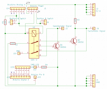
screenshot_3.png


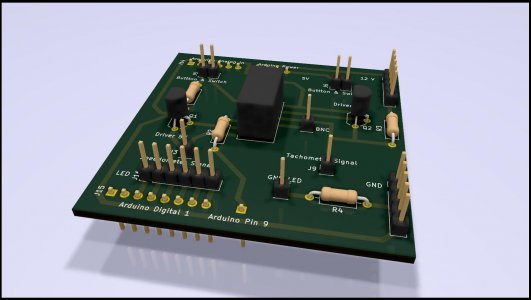
Corresponding PCB update - luckily no big change:
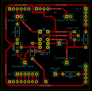
screenshot_4.png

GaugeTester3.jpg

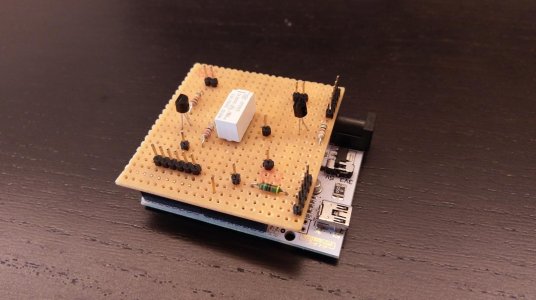
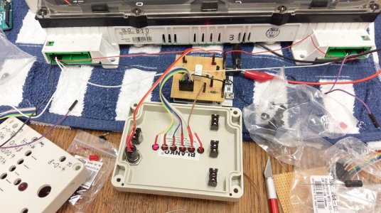
Looking at the first prototype PCB decided to make a new one, incorporating all the changes:
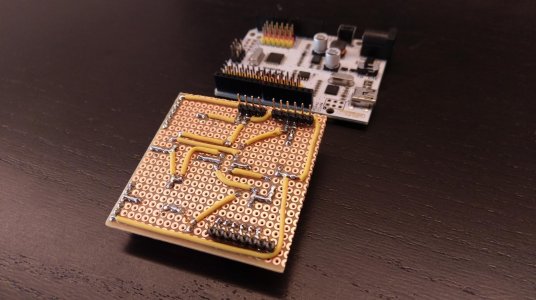
IMAG3736.jpg

IMAG3735.jpg

Then a few hours of programming to add button debouncing, Button, LED and signal generator control, start up check, cleaning up the code, etc.
All finished with a first test run connected to the gauge cluster:
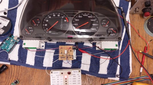
IMAG3733.jpg

As it's just have the fun with anything moving, here's a short clip with the uncalibrated cluster:


The right pin is going to be connected to the switch choosing between kmph/RPM, the left pin (connected to the push button) selects the value to be put out.

Once assembled it's a quick and easy way to calibrate:
  • Choose highest value and tune the top range potentiometer for a match
  • Jump to the lowest value and tune the low range potentiometer
  • Check highest value again and re-tune top range if necessary
  • Check all values for a match

That's how it looks like after calibration:


In addition, instead of an Aruino Uno we need a Freaduino as the 12 V power supply from the cluster is regulated down to 5 V and the original Arduino uses a linear voltage regulator to do that. It can take a maximum of 1 W. Unfortunately, the full setup takes 180 mA from at 15 V power supply (worst case) which means 180 mA @ 10 V are creating heat at the linear voltage regulator: 1.8 W - too hot to touch.
The Freaduino on the other hand has a switching power supply that can easily handle this task resulting in a mere 87 mA @ 15 V - pretty much ignoring the higher voltage and everything stays cool.

As for now, I'm playing with the resistors needed for the smaller gauges - unfortunately they need a rather high wattage so there is going to be another parts order, I'm afraid ..
 
Last edited:
Update

Long time no update as I had to fight with an IKEA delivery and some other stuff but here we go.

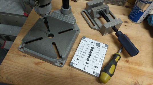
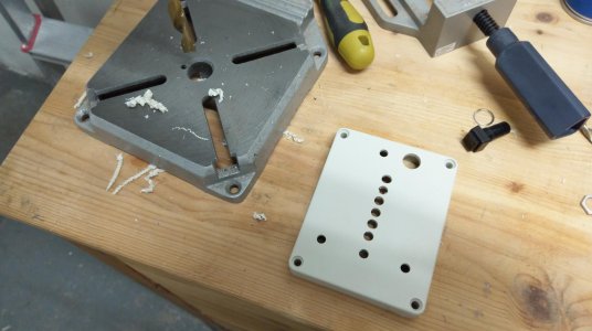
Preparation for drilling: New layout printed, cut out, and some helper lines added:

IMAG3791.jpg


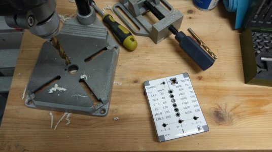
After drilling (turns out it easier without centre punching as plastic tends to bulge out around the mark which offsets the metal drill that was used):

IMAG3792.jpg


Removing the paper:

IMAG3793.jpg


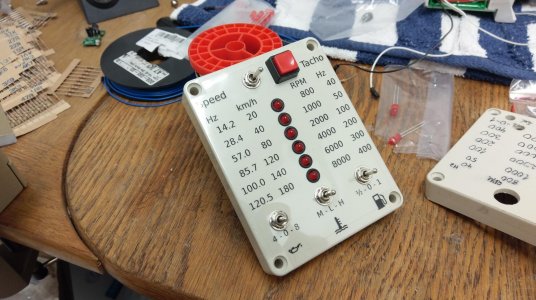
installing the laser printer foil (mirrored), cut out all the holes, installed LEDs, switches and the button (came out nicely and does not move around):

IMAG3796.jpg


Wired up and ready for prototype testing:

IMAG3797.jpg


Result so far (quick and easy to use, button debouncing works fine, I'm happy so far):

 
Nicely done up.

I would not have made it past the bench pulse generator, power supply, breadboard, some jumpers and alligator clips.
 
Thanks, Old Guy

It's definitely a little crazy but nevertheless fun to develop.
Once I tested that button and LED interface for the first time it just felt right :joyous: even after all the setbacks.

Nicely done up.

I would not have made it past the bench pulse generator, power supply, breadboard, some jumpers and alligator clips.
 
Thanks to you Big McLargeHuge as well.

When everything is done I would like to get a few (maybe five or ten) PCBs manufactured as the prototype boards are time intensive to build up.
There is going to be a write-up of everything including all parts. Code and design will be Open Source.
For those interested and OK with the conditions like a somehow slow build time (I'm running this in my spare time and not owning a business) I can manufacture them on request.

How cool :smile:. What are your plans for the prototype after you get your cluster bang-on? Mass production :wink:?

I'd be interested in getting one or building one from a kit or something once my S2000 cluster comes back and I have my original cluster on the bench.

What component is G6K-2? Some sorta double relay?
 
What component is G6K-2? Some sorta double relay?

Oh, sorry forgot to answer one of your questions. Yes, correct. It's a 5 V double switch relay (one magnet, two selection switches).
It's used to switch the Arduino signal output onto the correct driver circuits and at the same time switch the BNC connector (for an oscilloscope) onto the output of the active driver. Another way to check the signal going to the cluster.
 
I know I've not been tagged but the Oscilloscope is used to confirm the signal shape and frequency forwarded to the cluster but it's for visualization only.
The key component to calibrate the cluster is a suitable signal generator for 5 and 12 V rectangle wave form, I'm afraid.
 
@Heineken is correct. You need a pulse train generator which combined with an Arduino is what he has created. The DSO138 just displays the output to confirm that the pulse train is the right frequency and duty factor. The DSO138 would be useful as a check if you were using an analog signal generator for the pulse train which might have some calibration uncertainty. Heineken is generating the pulse stream in firmware on the arduino and the arduino's clock error relative to the pulse rate required for tach and speedo calibration probably makes checking the output to confirm the pulse rate unnecessary - unless you need the scope to confirm that you coded the arduino correctly. If I were using [MENTION=5430]drew[/MENTION]'s budget $2 signal generator for the first time I would probably want to check its output also.
 
Last edited:
I know I've not been tagged but the Oscilloscope is used to confirm the signal shape and frequency forwarded to the cluster but it's for visualization only.
The key component to calibrate the cluster is a suitable signal generator for 5 and 12 V rectangle wave form, I'm afraid.


@Heineken is correct. You need a pulse train generator which combined with an Arduino is what he has created. The DSO138 just displays the output to confirm that the pulse train is the right frequency and duty factor. The DSO138 would be useful as a check if you were using an analog signal generator for the pulse train which might have some calibration uncertainty. Heineken is generating the pulse stream in firmware on the arduino and the arduino's clock error relative to the pulse rate required for tach and speedo calibration probably makes checking the output to confirm the pulse rate unnecessary - unless you need the scope to confirm that you coded the arduino correctly. If I were using [MENTION=5430]drew[/MENTION]'s budget $2 signal generator for the first time I would probably want to check its output also.

Thanks guys. I'm going to grab [MENTION=5430]drew[/MENTION]'s $2 signal generator and check it against the DSO138. I assume for the 5V signal, you must provide a 5V power source, hence the cell phone charger? For the 12V tach signal, I assume a 12V car battery will suffice? Just want to make sure I get the wiring right so as not to burn out my gauge cluster that I just rebuilt. ;)
 
That should do the trick.
If possible, don't run the 5 V PWMs for too long as in the original circuit the tachometer is supplying the 5 V and the Vehicle Speed Sensor is pulling it down to ground. The PWMs from Andrew are not working the exact same way and could have side effects.
 
Thanks guys. I'm going to grab @drew's $2 signal generator and check it against the DSO138. I assume for the 5V signal, you must provide a 5V power source, hence the cell phone charger? For the 12V tach signal, I assume a 12V car battery will suffice? Just want to make sure I get the wiring right so as not to burn out my gauge cluster that I just rebuilt. ;)

It is almost certain that you won't be able to use the $2 signal generator to drive the tach or speedo directly. The signal generator could replace the Arduino in Heineken's cluster checking device. If you look at his schematic diagram in post # 26, the signal generator will replace the Arduino signal which comes in on jumper J13 (bottom left). You need the 220 ohm biasing resistor R2 and transistors Q1 and Q2 which invert the signal from the arduino / signal generator and have the current switching capability to deal with the pull up resistors used in the cluster. You also need R3 which is the internal pull up for the tach signal. Because the Arduino can be configured with open collector outputs it might be able to do this directly. The signal generator will definitely not be configured to accept the pull up current associated with the tach and the speedo so you need those transistors.

Yes you need both a 5v and 12 v supply. I recommend against using an actual car battery as the 12v source. If something goes wrong with the wiring car batteries can generate several hundred amps of fault current evaporating anything connected to them. If you used a 1 amp fast blow fuse with the battery that would limit the damage; but, I would be inclined to look for something with less oomph. A 23A (or A23??) alkaline battery should have enough oomph for this testing and should be cheap. I would still fuse it to avoid an accident with the cluster.

https://www.canadiantire.ca/en/pdp/energizer-12v-battery-a23-2-pk-0651053p.html
 
Last edited:
>It is almost certain that you won't be able to use the $3 signal generator to drive the tach or speedo directly.

?


I tested the signal generator on the Civic, then the Legend, and then the NSX cluster. I did it in this order because some clusters are cheap to replace. Now my available NSX has issues with the speedo, so the test of the NSX speedo isn't conclusive...however it worked just fine for the NSX tach.

I looked at the pulse generator you linked way back when. I saw the one that is still available has a drive current capability of up to 30 ma When I looked at Heineken's #26 post I saw that he was using a Freeduino instead of an Arduino because of the total load current of 180 ma. That is why I kind of ruled out the pulse generator. However, in retrospect he did say 'total load current' and he has a relay and LEDs (and the supply to the Freeduino) in addition to any load that may be sunk into the cluster so your experience suggests that the required output current capability from the pulse generator is much less than 180 ma.

The pulse generators likely use an open collector output with an internal pull up. I thought the VSS circuit used an internal pull up in the cluster and I was thinking that the cluster pull up plus the internal pull up might result in too much current for the pulse generators output transistor. If the VSS pull up is in the ECU, not the cluster then when bench testing the cluster there is no additional pull up current for the pulse generator to sink and you are likely good to go for use on the speedo (with a 5 volt drive voltage).
 
Last edited:
As [MENTION=7701]Oldguy[/MENTION] mentioned correctly, the Freaduino current issue is related to the extra 5 V current required for the relay and the LEDs. The 5 V speedometer output is just a transistor controlled pull-down attaching to the pull-up in the gauge so it doesn't have to provide current (just sink it). The 12 V source required for the RPM signal is taken directly from the 12 V power supply of the tester so - again - no extra load for the Arduino.

Coming back to the speedometer 5 V signal. It's a combination of a 5 V supply (coming from the gauge cluster) and a pulsed pull-down (by the VSS) - the tester emulates exactly that.
Andrew's PWM modules internal circuitry is not known to me. If it's able to sink enough current during its low (zero-voltage) cycle to pull down the gauge cluster's 5 V output sufficiently it should be OK.

Note that during the PWM's high (5 V) cycle the difference in output voltage between the cluster and the PWM can cause current to flow into the cluster which is not what's intended to happen - and the reason for my warning not to run it for extended periods of time.
 
All of you guys are basically convincing my to just buy a tester from [MENTION=30613]Heineken[/MENTION] LOL. I'm in over my head on this.
 
:biggrin:

The PWMs from Drew should be OK, just don't keep 'em running for more than a few minutes (which should be plenty for calibration).

If you're lucky, the new capacitors won't affect the result and just checking (no calibration) is sufficient.
Please make sure to order the right capacitors, there are some specials in there. The write-up contains an order list for digikey that you can use - after verifying that your PCB has the same capacitors on board (should be the case).

PS: The diagrams in the write-up are for the 1995-2005 pin-out but the table contains pre 1995 pin numbers, too. Pin counting is a little weird but printed on the PCB if unsure.
 
Last edited:
Back
Top