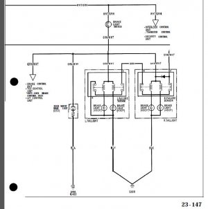
@
icefire, exactly at what timing did 'they first surface together'?
Was it while you were cruising at speed, pressing on the brake pedal or at the time when you turned the IG key into P2 ON position?
If both first showed up at the time of IG in P2 ON, then not surprised.
They both go through the bulb check mode at the same time but at different check process (BRAKE LMAP; about 2sec, SRS; about 6sec).
For SRS, please check
#1 fuse (10A) at the fuse panel inside the cabin.
From the factory, it is covered by a single yellow cover but it may be already gone.
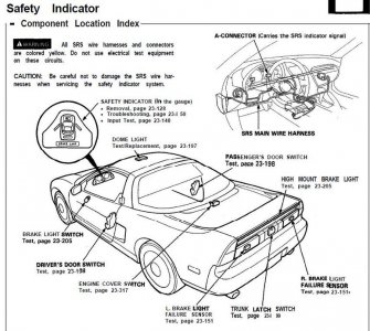
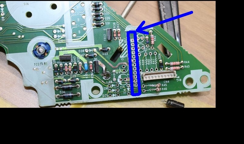
For the BRAKE LAMP warning light, when testing at the instrument cluster, you need to check the green connector at the LEFT side (looking into the cluster while sitting in the driver seat).
By the way, both green connectors are 30pin, not 22pin.
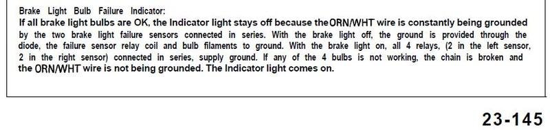
With both green connectors connected to the cluster and if you GND the ORG/WHT wire, the BRAKE LAMP warning light should switch itself off in 2sec after IG P2.
If it stays On, please double check that you are using good GND and also making sure that the ORG/WHT wire is not pulled up by other sources.
You may want monitoring the voltage of ORG/WHT wire while testing.
If it still stays On, I'm afraid the issue is inside the cluster.
For the SRS warning circuit, the idea is the same as the ABS, etc ones.
You need to keep discharging the RC circuit to prevent the Zener diode within the warning circuit from reaching the Zener voltage.
Or, vice-versa depending on how the circuit is designed to act.
For SRS light, you need to apply 10+V at the BLUE wire at the RIGHT (looking into the cluster while sitting at the driver seat) green 30pin connector at the cluster.
If the SRS light doesn't switch itself off, your issue is inside the cluster but very rare.
More likely to be blown
#1 fuse at the fuse panel inside the cabin (i.e., short circuit inside the SRS unit).
If you have aftermarket steering wheel/boss/hub, please make sure that whatever the method you used to simulate the presence of SRS is still fine.
With 91, dual SRS or seat belt pre-tensioner were not available so should be easy to check.
Kaz