This posting is part information and part advertisement.
The informational part:
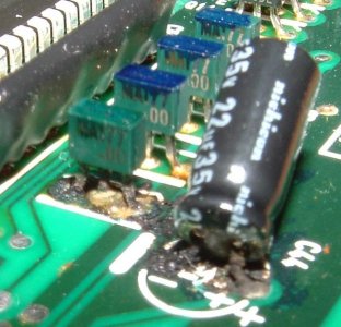
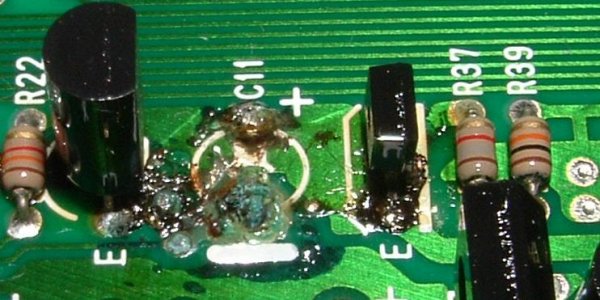
I have posted two pictures that show an NSX climate control board prior to being repaired. The original electrolytic capacitors start to leak over time (years) and corrode the circuit board pads, traces and component leads. The amount of damage that can occur from the leaking capacitors can be severe. I repaired one board that had 3 leaking caps which resulted in 15 corroded or broken connections and 4 corroded parts that had to be replaced (separate from replacing all 13 electrolytic capacitors).
There have many reports of failed boards and the problem seems to be widespread. If anyone ever has their dashboard apart, I strongly suggest that they have the board checked out and the capacitors replaced and any required repair performed. This saves the hassel of having to remove the board when it actually fails, and eliminates the risk that the board will be unrepairable because of too much damage and no spare parts. The cost of repair is one quarter the cost of a new board.
The advertisement part:
I have started repairing the climate control boards for the NSX, through Dali Racing. This consists of removing all of the electrolytic capacitors, removing the corrosion, cleaning, visual inspection of PCB pads and traces, installing new electrolytic caps, replacing any other corroded parts, repairing broken traces with wire jumpers, cleaning, and visual inspection.
Bryan Zublin
Zublin Engineering
The informational part:
I have posted two pictures that show an NSX climate control board prior to being repaired. The original electrolytic capacitors start to leak over time (years) and corrode the circuit board pads, traces and component leads. The amount of damage that can occur from the leaking capacitors can be severe. I repaired one board that had 3 leaking caps which resulted in 15 corroded or broken connections and 4 corroded parts that had to be replaced (separate from replacing all 13 electrolytic capacitors).
There have many reports of failed boards and the problem seems to be widespread. If anyone ever has their dashboard apart, I strongly suggest that they have the board checked out and the capacitors replaced and any required repair performed. This saves the hassel of having to remove the board when it actually fails, and eliminates the risk that the board will be unrepairable because of too much damage and no spare parts. The cost of repair is one quarter the cost of a new board.
The advertisement part:
I have started repairing the climate control boards for the NSX, through Dali Racing. This consists of removing all of the electrolytic capacitors, removing the corrosion, cleaning, visual inspection of PCB pads and traces, installing new electrolytic caps, replacing any other corroded parts, repairing broken traces with wire jumpers, cleaning, and visual inspection.
Bryan Zublin
Zublin Engineering