A french NSX owner sent me his Bose speaker amplifiers (and the radio - but we'll come to that in a separate thread) for repair. The car has been left in a garage for a considerable amount of time and the audio system was non-functional as not even the head unit would turn on. The PCBs were from 1992 and in a bad state:
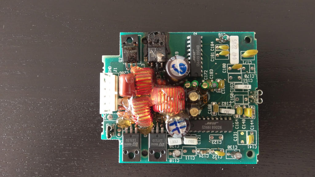
right door
The right door amplifier hat a blown MOS-FET transistor which charred the PCB. The Bose PCBs are rather robust and withstand a lot of abuse but there are limits, of course. The reason for this failure is (of course) capacitor leakage but also due to the design of the amplifiers. Their main ouptut stage is a MOS-FET transistor bridge that connects each speaker pin to either GND or VBAT - that's why there are four transistors.
The downside of this design is, that it fails catastrophically if a pin is connected to GND and VBAT at the same time - which happens if both transistor pairs are conducting at the same point in time. Such situations are usually avoided by switching the transistors correctly but in this particular failure case the acid from the capacitors carries voltage to one of the transistors, making it conduct permanently - if the second transistor is now activated it becomes a direct connection between GND and VBAT. Since the acid-affected MOS-FET typically conducts only a little at first, it keeps a remaining resistance which causes it to literally heat up and burn.
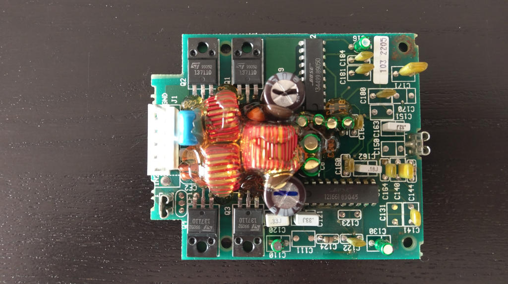
left door
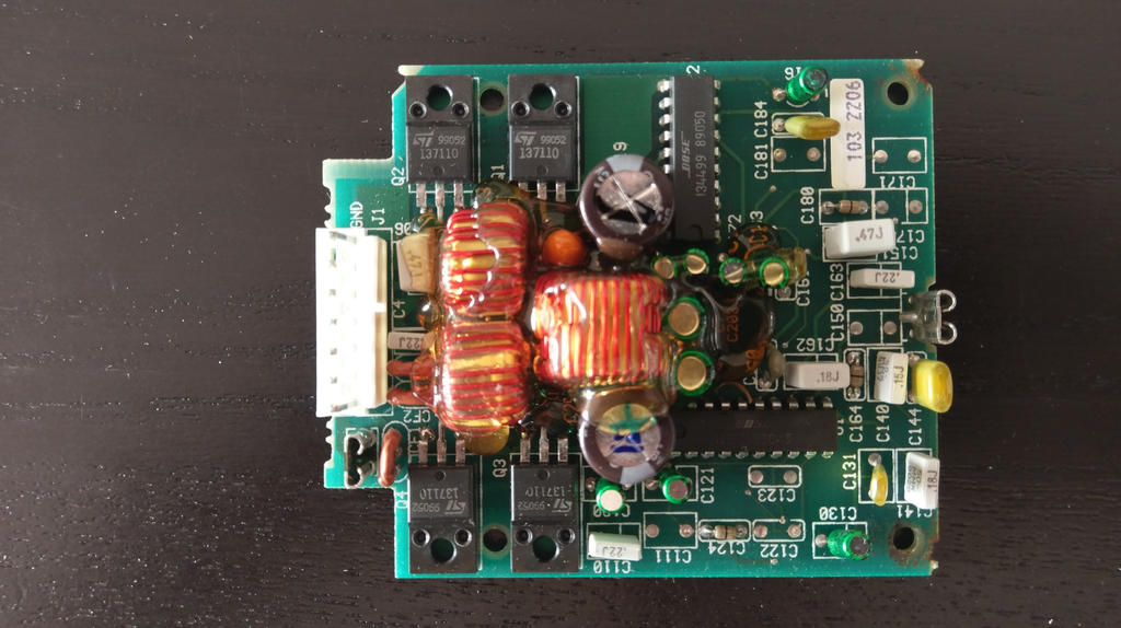
center speaker
Both left side and centre speaker amplifiers appeared normal from a first look. Due to the contamination with capacitor acid, all of the hot glue, all capacitors and the coils had to be removed. The PCB of the right door amplifier was washed with water and a brush, then rinsed with natural alcohol. Contaminated (dark coloured) traces were scraped of and polished with a fibre pen, then covered with solder. New capacitors installed and powered-up for a test.
Unfortunately, nothing happened. Checking the MOS-FET transistors reviled two potentially broken ones - their measured resistance remained too low to be correct. Event after replacing them with new ones (IRFIZ24N being a popular exchange type) no sound came out. Further analysis turned out that one of the Bose special ICs was broken - can't be repaired without a replacement from another amplifier.
One down, two more to go. The centre speaker amplifier worked fine after the same treatment so it got a drop of hot glue to stabilize the coils and new conformal coating to protect the copper traces. Same for the right door amplifier with the burned transistor. Repairing such damage is not exactly optimal but despite a real alternative it seemed like the only sensible path to take.
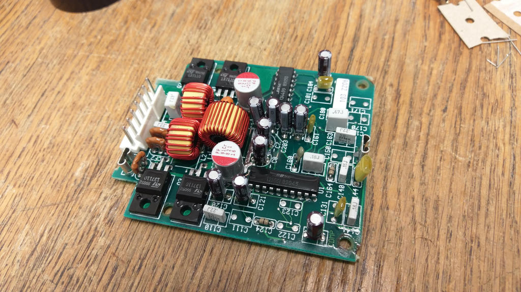
repaired center door amplifier (glue missing)
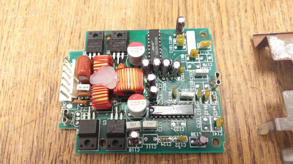
repaired left door amplifier
It's kinda sad that only two of the amplifiers could be brought back to life but much better than none. Usage of IRFIZ24N MOST-FET transistors as a replacement can be confirmed, which helps to avoid having to source "official" Bose parts which are sold for a premium.
right door
The right door amplifier hat a blown MOS-FET transistor which charred the PCB. The Bose PCBs are rather robust and withstand a lot of abuse but there are limits, of course. The reason for this failure is (of course) capacitor leakage but also due to the design of the amplifiers. Their main ouptut stage is a MOS-FET transistor bridge that connects each speaker pin to either GND or VBAT - that's why there are four transistors.
The downside of this design is, that it fails catastrophically if a pin is connected to GND and VBAT at the same time - which happens if both transistor pairs are conducting at the same point in time. Such situations are usually avoided by switching the transistors correctly but in this particular failure case the acid from the capacitors carries voltage to one of the transistors, making it conduct permanently - if the second transistor is now activated it becomes a direct connection between GND and VBAT. Since the acid-affected MOS-FET typically conducts only a little at first, it keeps a remaining resistance which causes it to literally heat up and burn.
left door
center speaker
Both left side and centre speaker amplifiers appeared normal from a first look. Due to the contamination with capacitor acid, all of the hot glue, all capacitors and the coils had to be removed. The PCB of the right door amplifier was washed with water and a brush, then rinsed with natural alcohol. Contaminated (dark coloured) traces were scraped of and polished with a fibre pen, then covered with solder. New capacitors installed and powered-up for a test.
Unfortunately, nothing happened. Checking the MOS-FET transistors reviled two potentially broken ones - their measured resistance remained too low to be correct. Event after replacing them with new ones (IRFIZ24N being a popular exchange type) no sound came out. Further analysis turned out that one of the Bose special ICs was broken - can't be repaired without a replacement from another amplifier.
One down, two more to go. The centre speaker amplifier worked fine after the same treatment so it got a drop of hot glue to stabilize the coils and new conformal coating to protect the copper traces. Same for the right door amplifier with the burned transistor. Repairing such damage is not exactly optimal but despite a real alternative it seemed like the only sensible path to take.
repaired center door amplifier (glue missing)
repaired left door amplifier
It's kinda sad that only two of the amplifiers could be brought back to life but much better than none. Usage of IRFIZ24N MOST-FET transistors as a replacement can be confirmed, which helps to avoid having to source "official" Bose parts which are sold for a premium.

