• Protip: Profile posts are public! Use Conversations to message other members privately. Everyone can see the content of a profile post.

bogle's 1991 mild build thread

You’re right, I should have looked into getting it blasted. There are probably local places with a media blaster. Maybe I’ll do that down the line. It is super pitted and some of the holes have been eaten away a little where the stock battery was, though, so that would still be there. But I guess not a concern as it’s all on the tray and the extruded tubes have no corrosion (other than normal alum white oxidation). I was thinking it’d be nice to get a clean one and have it powder coated black. For now it holds the battery off the ground, so it’s fine.

Yeah the old pads dusted quite a bit, hopefully these are better. Literally one short drive on the old pads and the wheels would be coated. Too bad your shiny RG3s are getting dirty! Hopefully the dust is easy to clean. Sonax is magic (on wheels, anyway)

I blasted mine with soda and it came out pretty good. Walnut shell or glass bead might get it more even looking/matte.

ACtC-3eel-wrmbgJ_2oSl3QvrSNio8UAzRzZ7TAFm1EmNa7sUDBXk23j0GXEJyjSMgV9K3ypC2pvdGUT-41KrjsEjxep0nOX73zjC-9eHmZCxi1EoD7G0cCYoJ1_yFzKQrgRSx3fCsUkzghmR3ezW_m85rZq=w945-h1260-no
 
A couple big things I've been waiting for finally came in: The 2nd wideband and the SoS big bore throttle body.

Wideband

Finally!

07f0c209c5f6ef07262e653f7c64b658.jpg


I'm running the analog-out into the stock O2 connector, then I also have a CAN bus into the engine bay so I can capture the controller's digital out as well.

f29c41515781b10cb713339b2ab8d793.jpg


Installed and running

cc8ee54cbf9a28c3c46da82f43b76594.jpg


They agree in some cases, but while cruising the rear bank is still a little leaner than the front. This jives with the old gauge / LSU 4.2 that the new controller replaces.

Throttle Body

I sprang for the SoS big-bore throttle body for a couple reasons, the main being that my TPS signal is super noisy--the only way to get a proper OEM TPS is to replace the throttle body. My throttle body was also realllly dirty and there's an alleged 9 hp to be unlocked by opening up the TB on a supercharged car.

Here it is

c4f516b13e34a675289b8e81de0e8313.jpg


A while ago I bought all the coolant hoses and all the clamps, so took this as an opportunity to replace the two TB hoses + clamps.

e00942f1bb3ed86e7a2f2f0660f44cba.jpg


The old, dirty dirty

34f8ef773c9ceac777b1637abdc2e787.jpg


One thing to note: it was way easier to remove coolant hoses at the engine than at the TB when removing the old TB. That is, the old TB came out with the hoses.

This would be a 20 min job without the coolant hoses, but ended up at ~1.5 hours. I managed to lose only about 1-2 oz of coolant and keep 100% of it off the tranny with a carefully positioned piece of plastic and a bread pan.

The new, shiny!

f7fd5b9f1c766db8aa41b5eb5d682a0b.jpg


I didn't bleed the coolant. It held steady around 180 while idling, and was in the 170s while driving, which is consistent with previous data.

Should I burp one of the bleeders just to be sure? If so, which one?

Bigger is better?

Old TB Specs

* Inlet: 68mm
* At manifold: 65mm

New TB Specs

* Inlet: 71mm
* At manifold: 66mm

The manifold itself is 66mm, so I suppose it's good they now match, and wouldn't make sense to be any larger. Does 1mm really make that much difference? Maybe the 3mm larger inlet creates a bigger/better venturi effect?

Generally the throttle response feels a little better, but it could be in my head and/or a variety of other things.

Does it feel quicker? No, but I also admittedly don't have a really solid sense for how quick it was before. I suppose the eventual dyno visit will be the judge.

Anyone else have experience with this thing?

TPS Verdict

Well, is the TPS better?!???!?????

No. It's actually MORE noisy. Ugh. The TPS saga continues.

FWIW, the SoS TB does not come with a NEW TPS, but a used OEM TPS measured to be within spec.

Using the old TPS I managed to set up the tip-in options such that there was no accel enrichment while cruising, with a couple hours data confidence. This "new" TPS is triggering it on the regular with the same ECU settings. It seems the old TPS would fluctuate about 4% while cruising, this one fluctuates about 5.x%. Seems small, but my threshold settings required a 4.5% change to enrich.

The white spikes here and subsequent AFR dips are the effect. Annoying. The spikes here are pretty egregious and weren't a thing with the old TPS.

115154722-2cc6cd80-a031-11eb-8b1c-282eea8bf0bc.png


You can also see the difference in front bank (O2 1) vs rear bank (O2 2) AFR. It's often about a 1/2 point different during cruising. In some cases they do mostly agree (idle, WOT).

One thing interesting here is that the new TPS appears to be NOT noisy above 30% throttle, with almost 0 noise at WOT. The old one was noisy everywhere in the range, including WOT. I don't really have enough data to have full confidence, though. Here's a pretty representative chart from my drive yesterday:

115154723-2df7fa80-a031-11eb-9b17-c6f18a269c93.jpg


One weird thing from my last pass on the tip-in enrich tuning is that, in the middle of a 15 minute log session, there was a whole minute where the (old) TPS signal had effectively 0 noise. Could this be the TPS making proper contact? Or maybe a ground in the harness being shaken in exactly the right way? In any case, this is what I am looking for. It sure would make tuning a lot easier:

115154719-29cbdd00-a031-11eb-8194-8bec7446d1b5.jpg


I still suspect the TPS is a problem. I have 2 new aftermarket sensors on order (Dorman and Omni Power, though they are probably the same unit). One upside of the new TB is that the rivets have already been replaced by screws, so no dremel necessary. If these new sensors are still noisy, I guess I'm hunting for a bad ground or something.
 
Last edited:
I replaced the TPS yesterday with an aftermarket piece in the hopes that it'd be less noisy than the OEM sensors.

Well, it's still noisy. It's now back to the same noise level as before the throttle body install.

116798022-8357f100-aaa0-11eb-831f-dd7d4412e74e.jpg


Now I feel like I have one of two things going on:

* This is normal and I need to work around it
* I have a wiring issue

My question for anyone listening is: do you have data on your own TPS? Is it noisy? How much does it fluctuate? Any screenshots you can share?

It's possible

* The sensor ground is connected to body ground causing a ground loop
* I have a bad crimp / terminal in the TPS connector
* What else???

Sensor Ground / Body Ground

Sensors have a dedicated ground in the ECU. If sensor ground is connected to the chassis ground, it can cause several problems, one is noise. A process outlined in this article is:

* Disconnect the ECU
* Check continuity between sensor ground & chassis ground
* If so, unplug sensors until there is no continuity

I disconnected the D plug at the ECU, and TPS ground (green/white) at the connector to body ground was 600k ohms. Not totally open, but not continuity either. Unplugged a few sensors, and still 600k. I will unplug all of them today just to see where the resistance is coming from.

Initially I didn't unplug the ECU connector and tested TPS ground to body ground....and there was continuity (~5 ohms). There was one forum post by one person who indicated this is normal, though, as the AEM ECU has a circuit going to body ground.

All the sensors: TPS, MAP, ECT, IAT, EGRL, VTEC pressure switches, IGN adjust, and both O2s share the same sensor ground (D22) in the NSX. It seems if this were the problem, all sensors would have noise issues. The ECT is a little noisy, but none of the others are.

If anyone has any insight, Id love to hear it!

More to come on the TPS install...
 
Last edited:
[MENTION=7151]mskrotzki[/MENTION] and [MENTION=33247]MotorMouth93[/MENTION] both have logs from the OEM ECU. They may have TPS data, but I don't know if the NSX ECU has the same fidelity as your AEM unit.
 
Last edited:
The TPS logs from my stock ECU show no noise at all.

Edit: To elaborate more on the fidelity of the reading, the OEM ECU converts the TPS voltage to a value from 0-200, so steps are in 0.5% increments. The noise in the screenshot above looks like the TPS value is changing by 3-4% which is quite bad and seems like there's some sort of problem either with the wiring or sensor.
 
Last edited:
Noted, thanks for the info. Yeah the noise seems pretty extreme.

I spent the whole day Sunday trying to diagnose it. Tried the 4th sensor: an OmniPower b-series sensor, it's less bad, but still 2-3%. Tried a sensor outside the car to eliminate mechanical noise. Tried NO sensor. Tried a resistor, all still the same amount of noise. With the car off it's 1% fluctuation no matter what's in the plug.

I also traced back the 600k ohm resistance between sensor ground and chassis ground. Turned out to be the pedal angle sensor (bottom TPS). Unplugged that, no continuity, but no change in noise.

The fact that the MAP sensor or any other sensor is not noisy is annoying. The TPS and MAP sensors are in a similar location, and use the same 5V and Ground. The (my) TPS wires run next to the injectors, though, maybe they are causing noise? It tends to smooth out at higher RPMs, or maybe just higher TPS voltage (>=30%).

I found a couple forum posts saying how the AEM v1's inputs were generally noisy, and a million posts about noisy TPSs & MAP sensors on a megasquirt system, generally with miatas. A few people fixed their noisy sensors with an RC filter. This dude in particular apparently totally reworked the AEM V1 ECU's input circuits with filters and better grounding to fix the noise.

My thoughts now are

* This is the way it is on this ECU, RC filter to the rescue
* Some problem with one or more of the TPS wires
* Injector or alt noise
* Maybe better ECU grounding? Some megasquirt people fixed theirs by fixing some grounds in the ECU, but not sure how that translates to the AEM

Time to buy a scope and a whole bunch of capacitors.
 
In between tuning-related activities, I've been tinkering with the interior here and there as parts filter in.

Shift / e-brake boots

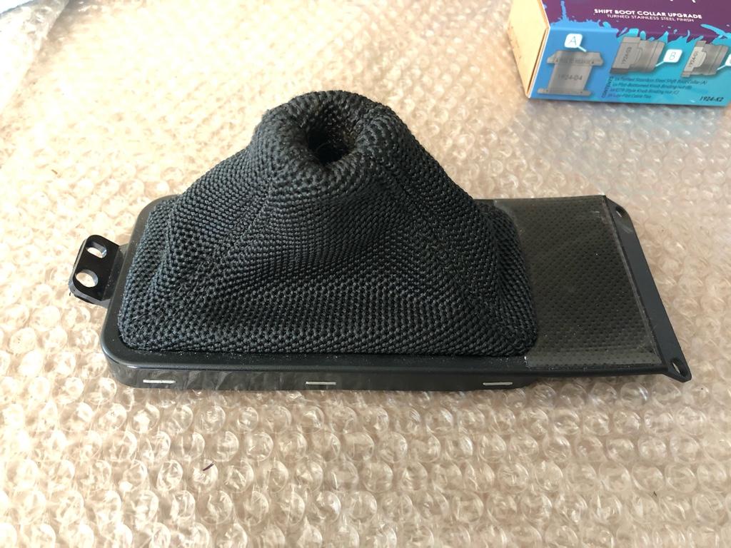
I haven't been in love with the mesh shift boot. It's kind of dirty, and with nothing holding it flush to the knob, there was always the sort-of-rusty shift lever showing through. The e-brake handle cover was in medium-to-whatever shape, the e-brake button looked like the straight out of an 88 civic, then the steering wheel, boot, and e-brake cover were all different materials. Overall it felt pretty haphazard.

48fb6049ce20ef1ef2643a790a63edfb.jpg


I was inspired by @BigMcLarge Huge's interior additions, so I bought a Redline Goods alcantra shift boot and e-brake handle cover to match the alcantra steering wheel. I also got a stainless Acuity shift boot collar and SoS e-brake button to round it all out.

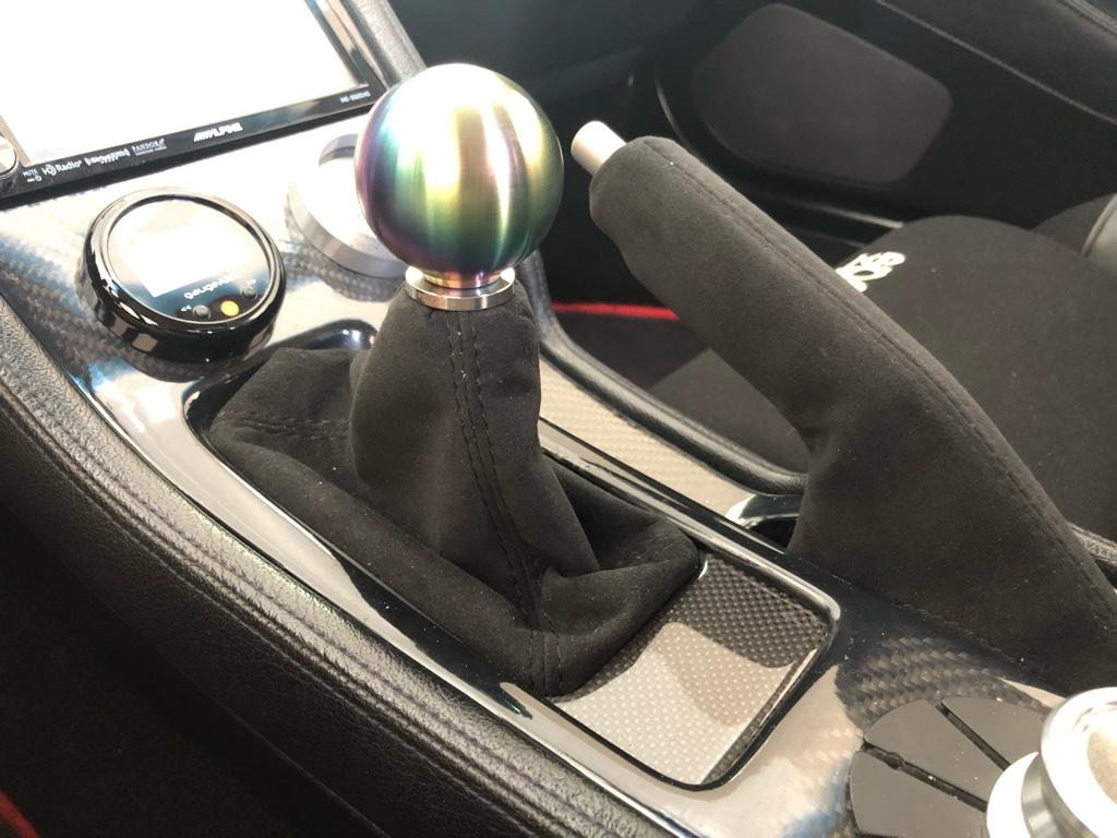
First was the shift boot. My car came with a boot setup resembling the NSX-R setup, I just reused everything but the boot. Before:

a37c14f08e5264e1f49b2d194e251b66.jpg


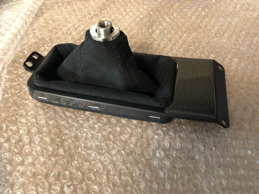
I used an awl and some needle nose pliers to carefully pull the staples out. I even ended up reusing all the staples in all of their original holes. Turns out I don't own a stapler, but you probably need a special one with low overhang for this job anyway. You can see the acuity collar on there. It is a super nice piece, and snaps into place with a solid thunk. New boot in!

5a3a71acd9e5b889aacc667cd61ca093.jpg


The e-brake boot was a little less straightforward. While the redline instructions for the shift boot were pretty detailed, the e-brake boot's are effectively: "Take boot, put it on e-brake handle." Do I put it over top of the old one? (no) How does even the old one come off? How do I make it nice at the button? (pics below)

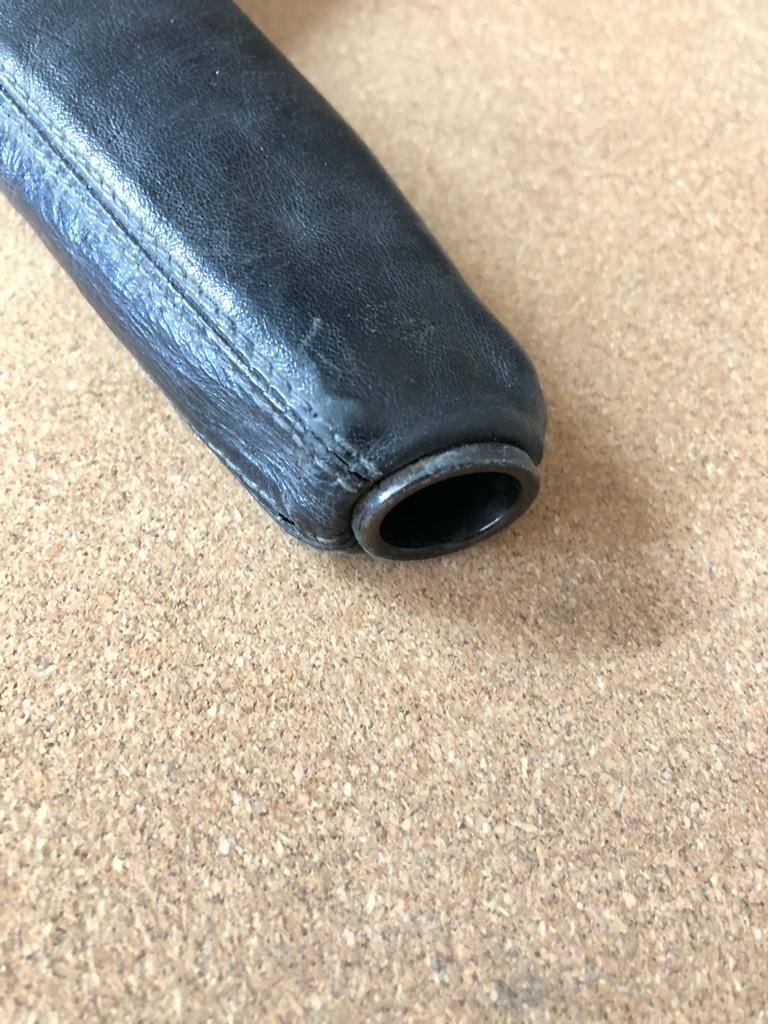
I unscrewed the old button, then stared and poked at the cover for a while. It's gathered at the button around a ring, how do _I_ do that with the new one?? Slide it over top the old one? Nope.

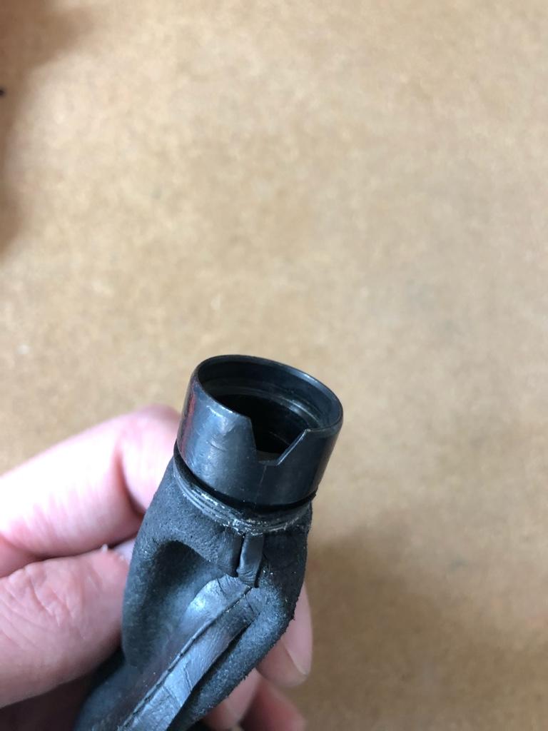
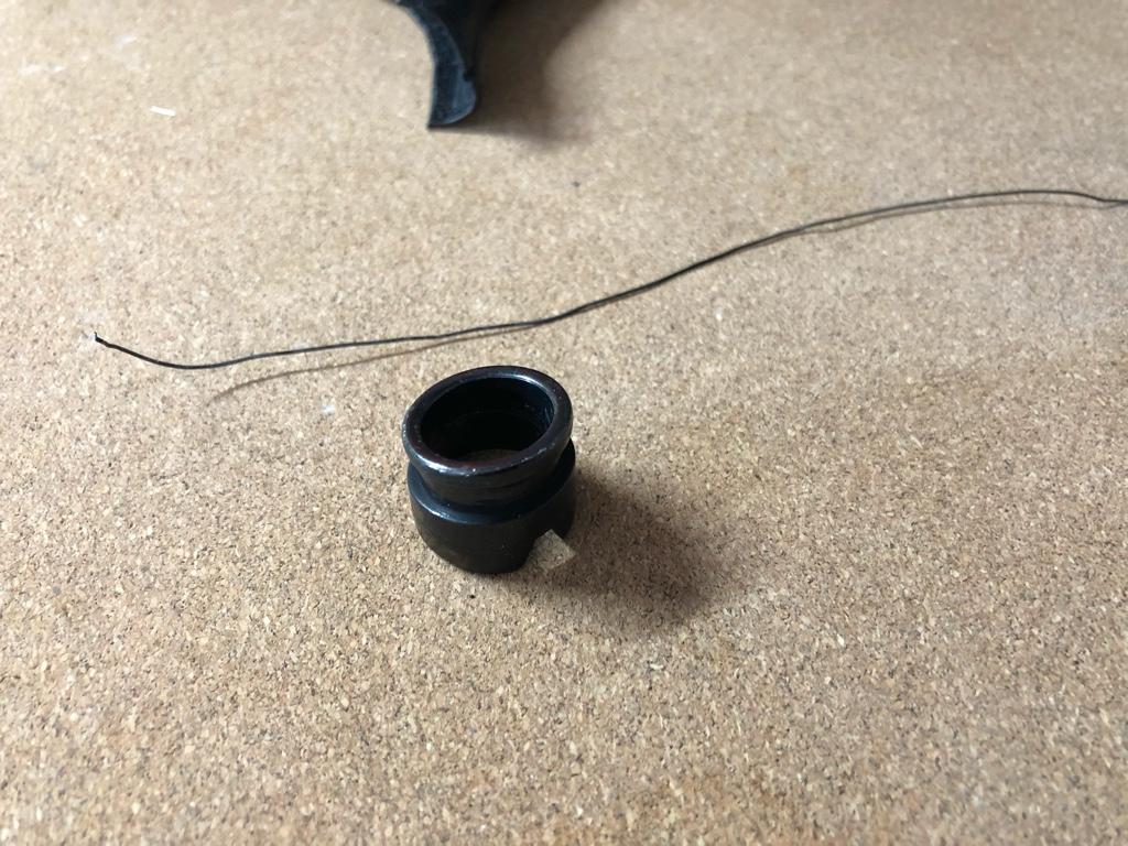
Welll, there is a little aluminum ring at the tip that pops out. I finally turned the old cover inside-out to discover this, but once the button is out, I think you could just jam your finger in the button hole (easy now), and pull it straight out.

5692472ee4a00a41fd7eff563b6a0e94.jpg


The ring is tied on with a piece of wire. My dad used to call this "aircraft wire". I guess I'm glad he wasn't an airplane mechanic.

530a6baebbea942d28da536db4a81745.jpg


dd0e3ad02fec649b203ad83752d191aa.jpg


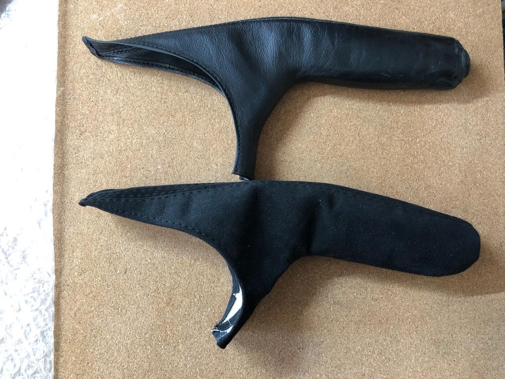
Ok, old top, new bottom

4a9b9d39cbc8fb14b32699c19b41fad9.jpg


I reused the wire on the new boot. Setting the ring on the boot in the right location isn't so easy, and the placement of it determines tip cleanliness once installed:

dc38df82358b2cb6d549a5808fcc4bbf.jpg


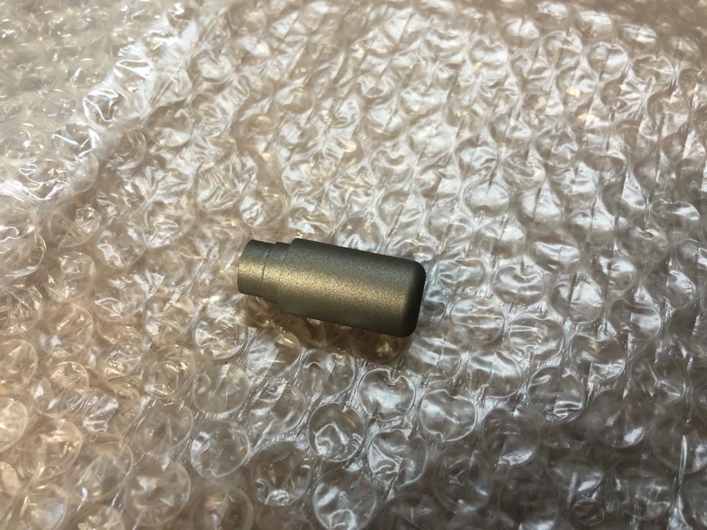
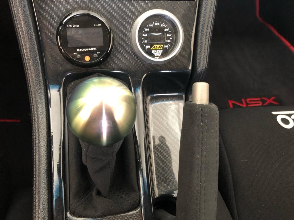
And finally, the new button. I went for the "titanium" color cause I figured it would match the wheel & NSX-S horn button. It's more grey than I was expecting, but all good.

f86e4c962eefc1fa2ab8a9a1aae1234d.jpg


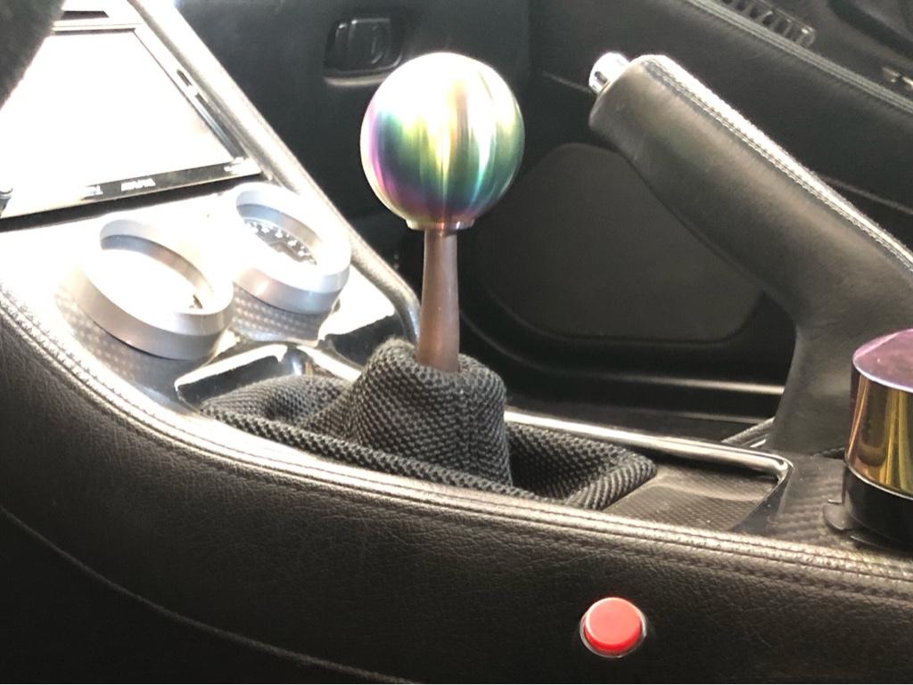
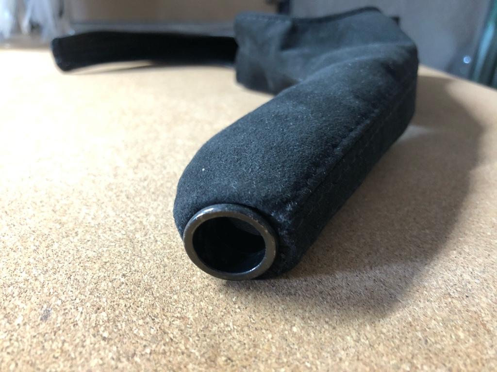
And here it is all installed

902b706ea0996a3cc3a65e7d1bb56f4b.jpg


133cd72ea846f64333ab0d15b5eb4db0.jpg


The e-brake boot isn't a perfect fit. It's both a little to short (rear) and too long (front). Sometimes I pull on the back of it when I get in the car like when you wear that shirt you know is just a little too short. My tip ring placement wasn't perfect either. But overall I like it better than the old one, and it's nice things match.

Well, things match except for the shift knob. I love the feel of the knob, it's a 1 lb stainless thing, but could be good to get a matching one. Ideally it'd be the same color as a later-model NSX-R knob. But I cant find anything in the same form factor as the current with no shift pattern.

Maybe I can get my shift knob refinished. Anyone know how the NSX-R knobs are finished? Alum + anodized? Just bead blasted?

Hopefully I managed to successfully work around the endless phallic-shaped landmines in this section. The temptation was real here--many opportunities presented themselves, but to each one I said, "No brain, this is serious business. The people of the internet do not need it." Please, if you notice anything, be it my restraint.

Seat rails

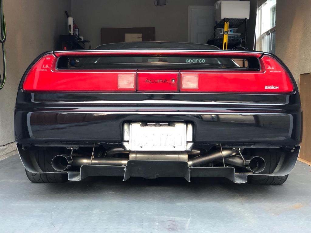
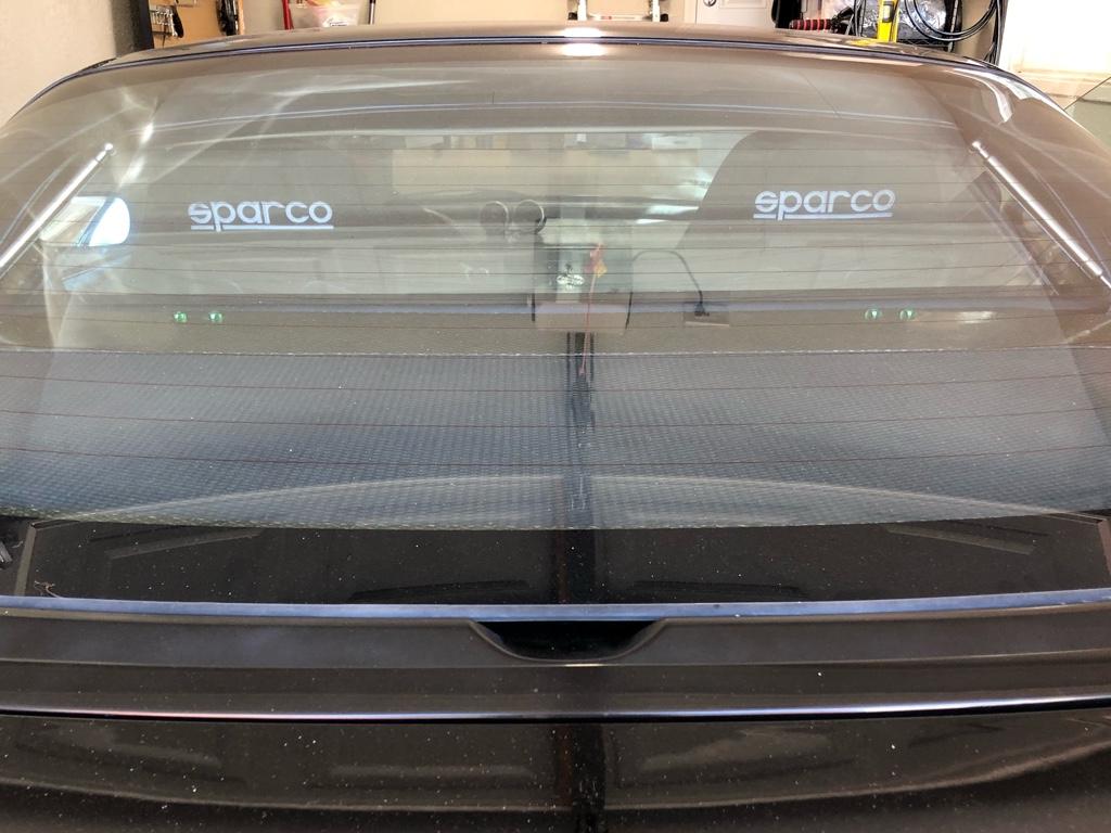
One of the first things I did to the car was replace the driver's seat rails with SoS low rails: I straight up didn't fit in the car. My first drive was slouched, head cocked, and knees hitting everything. The new rails lowered the seat by probably 2 inches and fixed all my issues, but the passenger seat was still high. Looked pretty goofy behind the car with "______ Sparco"; I'd notice it every time I opened the garage.

c1a97071d66d32ebe32588898159b615.jpg


Might as well have them at the same height, eh?

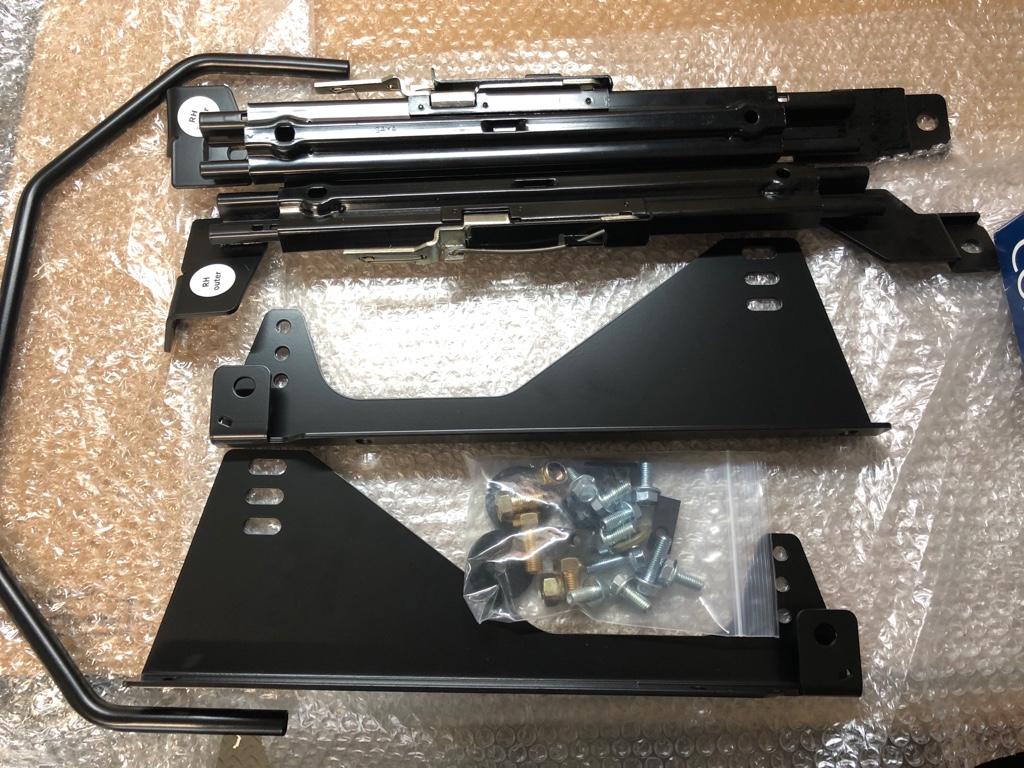
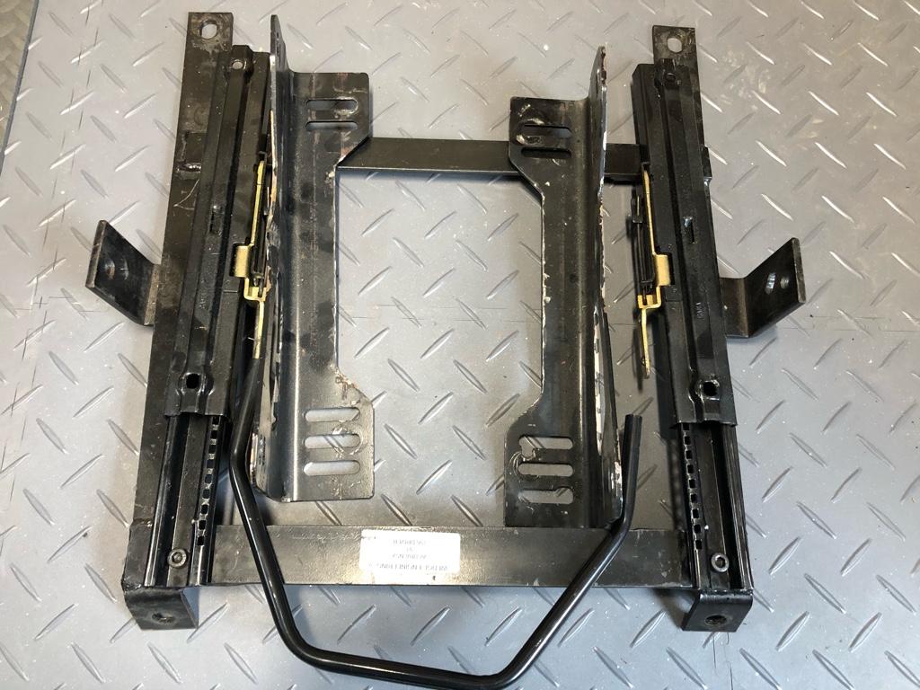
The SoS rails. The whole setup, hardware and all is 7 lb 14 oz. Would be cool if the uprights were aluminum, but it's fine.

bfa2a5f283b4e979b3b826c82823f494.jpg


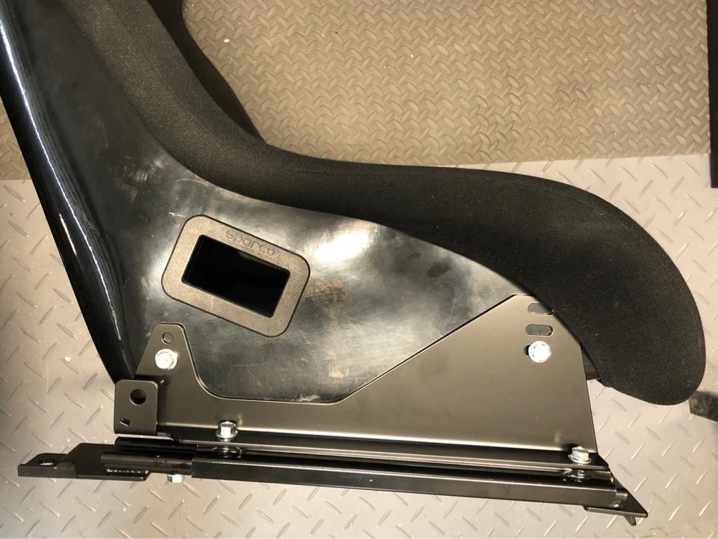
Installed on the seat!

a5e340f01284aa88bee791135a8cfb12.jpg


And the rails of old. It was kind of a hack job tbh. The mounts are wedge engineering bottom-mount brackets, then some chewed up, notched, and uh, relic'd uprights that clearly weren't made for the rails. All in, this old rail setup was 16 lb 12 oz (!!). The new rails saved 9 lbs (!!).

56e4dbc7838c55b6447b29795ce1f555.jpg


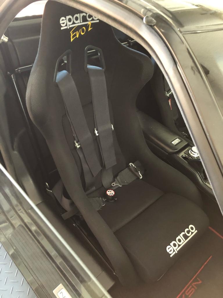
Having the seat out gave me a chance the weigh it. It's a 2008 Sparco Evo 2 and it was 17 lb 13 oz. I was under the impression that the seats alone were in the 25lb range, so nice surprise. I had been thinking long-term it'd be cool to upgrade to some lighter seats because racecar, but now I probably won't as anything materially lighter is a four dollar sign deal, per side.

Onto the install. An aftermarket part install on the car wouldn't feel right without a little struggle. There were a couple difficulties:

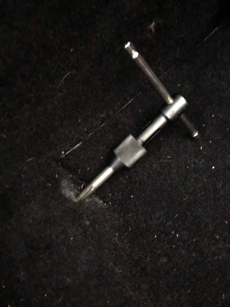
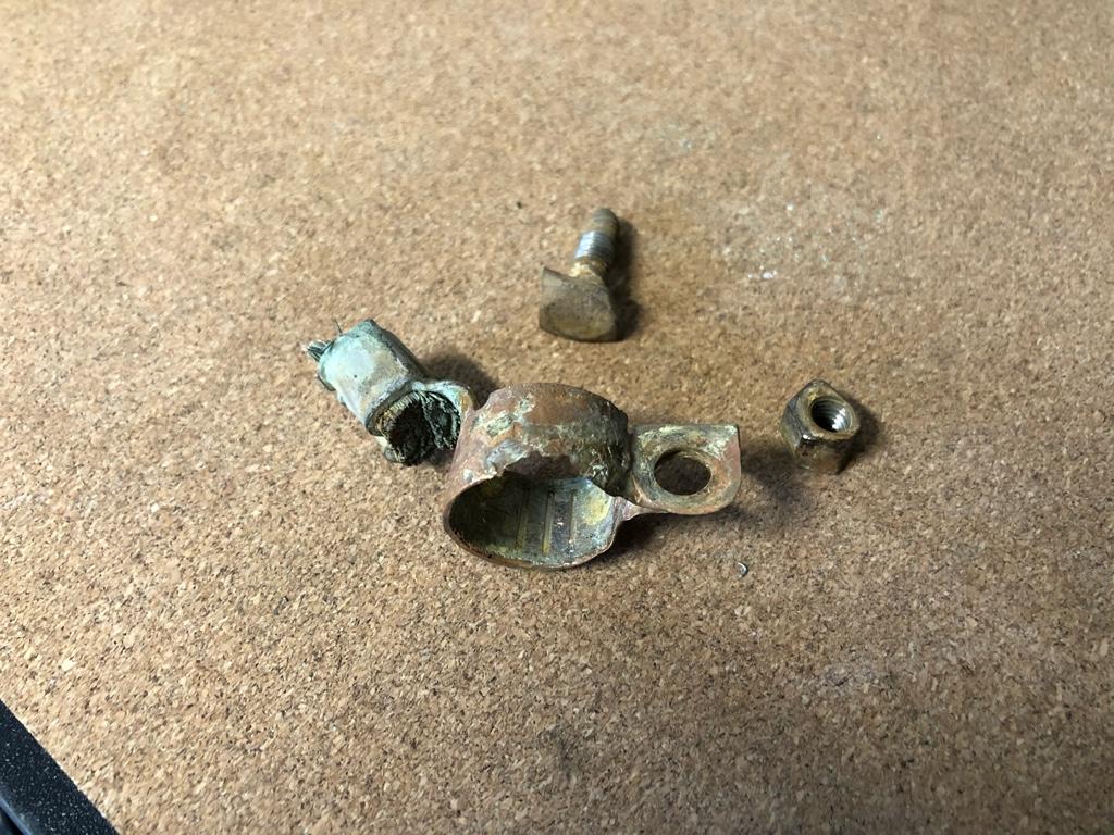
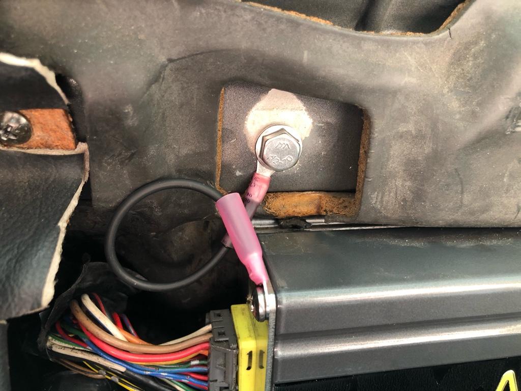
1: the threads on the front nut near the console were all boogered up. Did someone cross thread it? I could get a bolt in there a couple turns, then STOP. The old bolt wasn't in there very far...

I chased it with a tap verrrry slowly, 1/4 turn, back it out, repeat a little deeper. Pretty stressful--deez nuts are captive nuts. They have some play and can move around between a couple pieces of sheetmetal under the floor. I am not sure how much torque they can take before they round off, and I assume there is no way to replace one. It worked out in the end, though.

115e53b86a44a10f661d5bf2529390ff.jpg


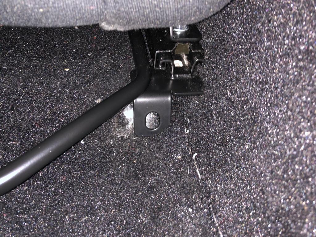
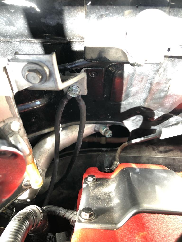
2: Post tap, sweat off my brow, this was basically my life for an hour:

5c696b261514f08a3b4d7b5fc8a2a3ce.jpg


The front of the seats are on the edge of the acceptable width for the rails. Between that, the aftermarket carpet being in the way of just about everything, the shoulder bolster hitting the door, and left front of the seat hitting the console, it was a pretty big pain to make fit well.

Does the passenger area, console to door, have less width than the driver area? Even by .5" - 1"? It seems like it does. I had similar issues with the driver side, but the passenger side was definitely more of a bear.

Installed! Yay! If you ride in the car, a rule is you do not get to adjust the seat. The door panels and console are curved in the wrong way in relation to the seat. It clears everything, but only just.

4dddc17416234c4f577f349ae743ee9e.jpg


Logo heights match!

42df330e0f2e78298b3cfd127eec2a73.jpg
 
Last edited:
I got a scope and spent a whole bunch of time this weekend measuring all the things, trying to track the dumb TPS issue down. I spent a lot of time on dead ends: e.g. shielding the harness around the injectors (no help), even making an RC filter harness that spliced between the TPS and engine harness (no help except when engine was off, then cleeeean).

I think it's the alternator.

I hooked the scope up to the alternator (+ on alt output, - on a chassis ground point) as an alternator ripple test. I was at ~1500 rpm running the lights cause I read it should have some load to really test.

The basic verdict is that there are small spikes on each cycle, and huge spikes every like 20ms; literal whole volt spikes. Scale:

* Each X division is the Time value in the bottom right
* Each Y division is the CH1 value in the bottom left

d1dc7c1d3321183c3500eb5fd561fd50.jpg


154793fc752a4bb47178856a17bd2096.jpg


Anyone know if spikes like this are normal? It seems like a hard "no" based on the ripple test articles I've read on the internet (good: 0.1v max fluctuation), but mine also doesn't look like any of the classic failure cases.

These spikes coincided with TPS voltage spikes at about the same frequency. Not sure if it's EMI as it appears the TPS wires run under the alternator, or the voltage change.

This is the 5v at the TPS connector (not TPS out).

3b2e5943b6f46aa658190696926d08db.jpg


It sometimes fluctuates 0.4 or 0.5v

9f189d850c2204bb7e183bf6432f0ec8.jpg


The map sensor's 5v, however was clean. It runs through a different part of the harness. I tried to pause the scope where it was showing noise, but this is as big an error as It ever had (50mV) on the map connector

1a3ae140b779b78f88549ae1488f9861.jpg


I would think that any crazy alternator voltage spike issue would affect a lot more than one sensor. But who knows.

I ordered an alternator (Denso 210-0216 80A for a prelude cause CTSC), hopefully it'll be here by next weekend.
 
It’s true, there was a lot more noise than I was expecting at the TPS connector. 0.4v is 10% of the range which is crazy.

The alternator noise is interesting. Based on the possible failure cases I’ve read about, my patterns look pretty different. It appears my rectifier is all good (minimal amplitude), stator is ok (same, and it charges). Is a bad regulator causing the spikes/drops/interference? Something else? I’m no EE...

I considered unplugging the alternator but I was nervous about harming the battery. Good to know I’d probably be ok. I suppose I don’t know for sure the alternator is the problem
 
i think im having the same issue with the tps noise with the aem unit. i luricated my throttle cables, re caliprate the tps. still the tps would act like you would have a stuck throttle cable or a lil idle surge like a vaccum leak, but it settles down after a couple sec.
 
Interesting, good to know. Are you on a v1 ECU? Have you done any logging?

I still haven’t solved it, but mine is definitely an electrical problem. I did read that these ECUs are really sensitive to grounding issues. I have a couple more ideas related to battery cables and general grounding. But so far I’ve been wrong about all of the many things I’ve tried.
 
Last edited:
I guess an update is in order. I installed the alternator last weekend, plus tried a whole bunch of other things to no avail. Still noisy.

The new alternator. An upside here is that the sticker better matches the other red in the engine bay, and it's clean. I suppose my strategy here is detailing it by replacing parts.

3131fa75bcd0f4a6931cedb47f334520.jpg


While the car feels like it runs smoother, it's still noisy AF at the alternator between the output and chassis ground. The spikes are actually more consistent than with the old alternator

6415f2502fb372944531e3afb767e86f.jpg


There is absolutely 0 noise at the battery terminals with the car running. I am no electrician or EE, but it leads me to believe I got some issues with the battery -> body/engine connections. Maybe even the negative terminal-to-body connection. I know some other people here had a smoother running car by replacing the negative wire.

I tried a bunch of other things, though. In the moment, I was thinking maybe the pathway the TPS was picking up EMI from injectors and the alternator (e.g. why is the map sensor's 5v clean?). But now I feel like I have eliminated that as a possibility.

* Tin foil shield the harness all the way around the injectors and under the alternator: no help
* Try an alternator capacitor cause why not: no help
* The pedal angle sensor is not used by my ECU, and it runs in a totally different part of the harness, on the driver's side, near the map sensor, and away from the noisy things. I ran its signal into the TPS input (From F6 to D11), using its power and ground: no help
* I ran my RC filter (1k, 10uF) to both TPS sensors through the pedal angle sensor wire. It cleaned up the output a good bit, but no different in the logs

Sensor signal out (the pedal angle sensor looked similar) before filter

f800301007736fc39d5a84ef7ad166ec.jpg


And with the filter it looks a lot better:

39b144a44ff1f25ead4333e189acb721.jpg


Buuuut still noise in the logs. The noise shifted around a bit with some things I tried, like there were fewer spikes with the pedal angle sensor input, but the ultimate amplitude as registered by the ECU was the same, so still a pain to tune.

Maybe interesting is that TPS sensor ground to body ground had the same pattern as TPS ground to 5V. It seemed like there should maybe be a voltage offset, but not crazy interference. I wish I had a gremlin-less car to compare against... (same pic cause it was the same pattern).

11ad9359b37a1adbd0f76db3b8aebb48.jpg


My plan for this coming weekend is to clean up all the grounds, make sure the ECU is getting good power / ground, try some extra ground wires, etc. If no change, then I'm probably stumped for a while.
 
Interesting, good to know. Are you on a v1 ECU? Have you done any logging?

I still haven’t solved it, but mine is definitely an electrical problem. I did read that these ECUs are really sensitive to grounding issues. I have a couple more ideas related to battery cables and general grounding. But so far I’ve been wrong about all of the many things I’ve tried.
Yes i am running the aem series 1 ver2
 
I went down another rabbit hole today: checking & cleaning all grounds, adding a few ground wires, and replacing the very corroded battery terminals. Verdict? TPS is still too damn noisy.

Overall, the grounds were in pretty good shape, and the connections, especially the ones with boots, were corrosion free. There's really only 3 of them, so I cleaned each one and their contacts.

My terminals were in rough shape. I wanted to replace both whole wires with new OEM ones, but they were backordered in the US, and I wanted to see if they were actually a problem. So new terminals.

The Neg terminal

0f9ed832e97ca2049826525e2974e1ad.jpg


And the positive terminal was mostly eaten away. The nut now takes a 3/8" socket cause it's so chewed up.

2b7208adad90b49a29cf192cc387025f.jpg


And setting up the new neg terminal. The negative wire was smaller than the 0 gauge hole, but larger than the 4 gauge hole, so I used a piece of the shim**they included with the terminals.

fad9a76cfec72c295c22261bd6041d55.jpg


And all on the battery

d4e35b3c1d49fbaa8f56076101d9fe4c.jpg


And I added 3 grounds:

* Firewall to TB: TB was 5 ohms to body ground
* Firewall to G-101: more below
* G-3 (under the alternator) to the front valve cover: this is a stock ground, but it was moved to a different location on my car

Firewall connection

d38a942f0ffbd10b607a77c835bfdaaf.jpg


Throttle body

71e5b68c504dd62d81522a57a22fd46a.jpg


Here's G-101 on the intake manifold next to the rear fuel rail. It's the main ground for the ECU. Both ECU ground pins (A23, A24) are routed to this ground. I thought this might be the culprit as it is powdercoated under the ground, and the bolt was pretty dirty. I didn't take a pic post-new-ground, but trust it is now there.

40bf662ea8ce8e652a8a3052d7eb993a.jpg


After all this, I started the car feeling confident that "this could finally be it". Buuuut nope. It actually appeared more noisy in the logs (>5% change), and the scope at the TPS sensor showed the same as before.

I had one more thing up my sleeve: grounding the ECU case to the body. It's just sitting on the firewall rubber, not bolted down. A big metal tab that looks OE is holding it down, but the top of the case is powdercoated. It measured 50ohms, so I grounded it to the firewall.

40596d8073d6c371642bbca850d02afa.jpg


Well, this dumb little ground actually made the most improvement. After, deltas were in the 2-3% range. But there are still the occasional 5% spikes, so unusable.

Whats next?

I'm semi stumped, TBH, and pretty over trying to track this down. I'm back to thinking it's something with the TPS / Throttle angle 5V pathway through the harness, EMI, or otherwise. Or it's the ECU sucking at handling some ground situation.

Throughout all this, the Map sensor signal is still clean. It blows my mind cause somewhere in the harness, the Map and TPS 5V + ground are connected together. I'm sure the T location in the harness matters, but I don't know enough about electricity to know the implications of the connection points.

E.g. the map sensor gets both D19 + D20 5V AND D21 + D22 ground. According to the schematic, D19 + D20 and D21 + D22 are connected together near the Map sensor. The TPS gets 5V from D20 and ground from D22. But since they are connected together at the Map sensor, I would assume the TPS is effectively getting both 5V and ground also.

One idea I have: there is an "Ignition Adjust" thing right next to the Map sensor. It T's off the map sensor's 5V and ground, and runs into D8 through the same part of the harness as the Map sensor. My ECU does not use this. Sooo, I'm going to try this pathway for the TPS power, ground, and signal. If it works, I can forget about this for a little while.
 
Last edited:
Using an alternate signal pathway sounds like a good idea at this point. Another option is the EGR valve plug, there's a 5V, signal, and ground wire right there next to the intake manifold.

If that doesn't help, you could try putting a crude low pass filter (resistor + capacitor) on the TPS signal as well.
 
Last edited:
Yeah I should put the EGRL 5V on the scope, it is closer. IIRC it runs over the engine and through the passenger side harness, so I wonder if it suffers from the noise. The map sensor runs into the car on the driver's side then along the floor to the ECU. I originally thought the pedal angle sensor pathway went through here, but it actually is in the same part of the harness as the TPS.

I did build an RC filter (1k, 10uF) and tried it on both TPS sensors through both TPS and pedal angle sensor signal wires. The filter is at the sensor, and it cleaned up the output at the sensor, but not much different in the logs. So it seems either there is EMI on the way back to the ECU, or the ECU is using a messy ground when ADCing. I bet if I put the filter at the ECU it would fix things, but I've been reluctant to cut or splice any wires at the ECU.

Sensor signal out before filter

f800301007736fc39d5a84ef7ad166ec.jpg


With the filter

39b144a44ff1f25ead4333e189acb721.jpg
 
I did a couple more experiments yesterday and ...... the logged TPS value is still noisy as ever. Note the random white spike and resulting AFR dip.

120123518-19e10600-c164-11eb-804b-84cc0edff35c.png


Things I did:

* Ran the TPS signal through the ignition timing adjust path. This pathway was a lot less noisy than the TPS pathway. The OG TPS path 5V has a 500mv oscillation, this pathway was only 50-100mv (even at the ECU). It basically T's off the map sensor path, which is clean
* Ran a new ground from G-101 (ECU grounds) to G-3 (under the alternator). The ground in the previous post I thought was G-101 is really G-103 (igniter). Now both G-101 and G-103 have better grounds.

My harness from the ignition timing adjust to the TPS. It reaches both sensors so I could try either one. No wires were cut, fortunately 90% of the engine bay connectors use the same terminals.

ea38a68cd98a79970f7bd263842cc468.jpg


Installed

ab91f38d98c53b6eb6076fe874f72c3d.jpg


And while I was in there, I cleaned up some other wiring. This is the AIT connector which now has a proper sealed connector. I _did_ cut the wires here, but if I go back to an OEM air sensor, I can make a patch harness.

24b89d7b45139e5a90d1d7db10183acb.jpg


???

Ok, but with the less noisy path, it should be like 1/5 the noise in the logs, right? But it looked exactly the same. So dafuq could be the issue?

A guy who has chased this down on an AEM V1 in his turbo miata got back to be, and we emailed back forth a bit. He fixed his by improving some things in the ECU itself.

The problem is internal to the PCB layout. Newbie engineer mistakes, which I'm constantly fixing ... [it] is not caused by where you run your wires. The main issue is the PCB itself has mistakes that cause the injector currents to couple into the TPS signal.

Given all I've tried, right now improving the ECU is the only idea I got left. Apparently there are a couple things he did, and some simple changes may solve a bunch of the noise. Imma try to work with him and get the details, or send him the ECU for the full meal deal.

Throughout all this, I've been researching an upgraded standalone cause working with a discontinued box is a pain. It seems there are really 2 options: Infinity or Haltech elite 2500 (or 2000). Both would be significant effort to get cruising back to where it is now + require it to go to the dyno. The infinity option is 2/3 the cost ($1k less all in) and a little easier (basemap from SoS, I have AEM CAN widebands already, I know how to use AEMs software), but the Haltech feels like a better long term option (software & support probably better, worried about obsolescence: infinity is 10+ years old and word on the internet is AEM is done with gas engines, I'd generally like to get away from AEM).

Ideally, though, I can just get some of the noise out of this dumb TPS pathway, make progress on the rest of the car, then in a year or 2 pull the trigger on a new ECU.

I'll explore the ECU mod option and if that doesn't pan out, maybe forget about this for a while. I haven't driven the car just for fun without the laptop in like 2 months. It mostly does the right thing, just kind of a crap-shoot as to when & how much fuel it adds. Sometimes it nails it and throttle response is crisp. But sometimes it bogs or randomly adds when cruising.
 
Last edited:
[MENTION=36953]bogle[/MENTION] I just want to say this is one of my favorite threads on Prime. Thanks for documenting all of your adventures- you really are our kind of people. :)

If I were you, I would go with the Haltech. While the Infinity is an improvement over the V1, I think the Haltech is going to get you that OEM-like operation and reliability. If my OEM ECU tuning experiment fails, I'm putting a Elite 2000 or 2500 in my car.
 
Thanks! That’s high praise. Cant wait to move on from this issue. I got 5+ other big projects I want to get to and I get a pretty limited amount of time each week to mess with the car.

On the Haltech, I’m definitely leaning that way, I’ve 80% talked myself into it. I was going to spend some time with their software, make a basemap, and get a feel for it this week, then make a decision. My thought right now is the 2500 for the extra logging speed.

Part of my extra price/complexity reasoning for the haltech was that ultimately I’d want to run their CAN dual wideband controller. But realized I don’t need to do it all at once. I can use the aem widebands and just run in the analog out like I’m doing now for a time, then eventually swap out the controller
 
I tried a couple final things last week(end) and managed to get a slightly calmer TPS signal. My hypothesis was that the ECU's TPS input was noisy, probably picking up noise from the injector signals.

The ECU has the ability to pick which ADC channel the ECU interprets as the TPS signal. The test was to reassign that to some other open input, then move the wire to the corresponding pin. I didn't do this earlier because the AEMPro software doesn't let you pick "ADCR3". Instead it's "MAF Voltage" or "PR Press Voltage". I don't have most of the named things, so I had no idea which ADC channels they mapped to. I learned last week that the AEMPro manual has a map of ADC channels to these sensor names, and I have a map of ADC channels to pins, so now I could test the other channels.

I had 4 empty inputs so I figured I'd try them all. I should have like 8 total: the EGT inputs also, but I think I have a very early Series 1 box. Mine doesn't have a proper "F" ECU connector, instead a pigtail going into the D connector.

* ADCR03 - D8 - "MAF Voltage"
* ADCR11 - D12 - "PR Press Voltage"
* ADCR13 - D6 - "Gear Volts"
* ADCR14 - A19 - "Spare Temp Voltage"

Only 2 of them actually worked as expected: D8 and D12. I think this is also probably because it's a super early Series 1 box, some pins probably aren't as advertised in the "latest" NSX Series 1 docs.

Ok, first D8, the "MAF Voltage". Noisy AF. It looks about the same noise level as the TPS input. At this point I was a little disheartened thinking they'd all be like this. Why is the MAP so clean? I still don't know.

120908933-4d200b00-c624-11eb-9f8d-5c58e9b5190c.png


Then D12, "PR Press Voltage". It's .... actually better. The MAF and PR Press logs were taken minutes apart with no changes other than the input. The vert scale of the top graphs is different than the first screenshot so the TPS looks crazy, but the scale on the bottom panel is the same. Delta noise is like 1/2 the MAF signal, and there are no major random spikes. It actually only picks up the changes like it should. I also tried the RC filter on this input, but it was no help. It def cleans up the input voltage a little, but the logged noise is same or weirder.

120908931-4b564780-c624-11eb-846e-e373d5421f5c.png


The real test was taking it out for a drive. I changed up some other settings to work around the noise: slightly decreased sensitivity, pulled some trim % at lower rpms, changed threshold. Overall the car feels better, crisper, doesn't randomly add fuel, gets it right when it matters: bigass throttle changes, and is pretty ok on smaller ones. It does miss some small changes it should pickup, but I can probably lower the threshold a bit.

Here's a shot from a drive today showing the lower limit where it's correcting. It picked up the actual changes and wasn't super messy. One delta in there it should have picked up, but didn't. AFR stayed in the 14s tho, so whatever. It still looks pretty noisy, but the lack of spikes seems like the major improvement.

To be clear, this is the main TPS sensor going through the ignition adjust pathway, connected to D12:

120908927-47c2c080-c624-11eb-96e3-85da97dcc38f.png


VTEC, yo

As part of digging around in all the wiring, I found out that the rear VTEC solenoid was NOT actually hooked up (!!!!).

The VTEC solenoids run through the ECU's F connector. My ECU has no F plug, so they were fed in pigtail-style. The car harness was not cut, there is a socket to pigtail running into D7 (front) and A19 (rear).

Here's a pic. Blue wire with butt connector is rear, front is the yellow wire with the piece of red tube on it below. Ignore the previously-tapped wires in there, been meaning to put some shrink tube on them...

d78699b8293018f90834a0f9b4d6ef46.jpg


Turns out (a) allegedly A19 is an input and (b) nothing in the ECU cal was enabled for the rear VTEC. It's possible A19 is configurable as a 12V output, but I couldn't find anywhere to do that. I set it so VTEC would turn on at a low RPM in the driveway and measured both outputs. Only D7 had 12V when it was on. :/ I'm sure the rear solenoid hasn't worked since the ECU install, pretty incredible it still made 400whp...

I ended up running both solenoids off D7 for now, and replaced the butt connectors with a HW090 plug. No pic cause I forgot.

TPS saga over for now

Well, I'm done digging for the issue. It seems like the ECU inputs. Hopefully it'll be totally resolved when I upgrade the ECU in the next several months.

The upside is that this process made me understand a whole lot more of the car, and a lot more of what has been done to it. Overall the car runs quite a bit smoother, probably due to some combination of the alternator, and better battery / ground connections.

I took it out on Saturday and it felt really really fast. It was a little cooler than usual, air temps in the 120s - 130s, both banks were actually going into VTEC, and also the throttle response was better cause it's less rich on tip-in.

Now I already have the interior torn apart for the Great Gauge Migration
 
Last edited:
Mine has the small plug for the VTEC connector if that’s what you’re referring too. I’ll get some pics tonight.

That’s wild that the rear VTEC solenoid wasn’t engaging at all, I’m surprised it wasn’t noticeable and I bet it’s a good bit quicker now. I guess it would just run rich on that bank before?
 
Last edited:
Back
Top