• Protip: Profile posts are public! Use Conversations to message other members privately. Everyone can see the content of a profile post.

bogle's 1991 mild build thread

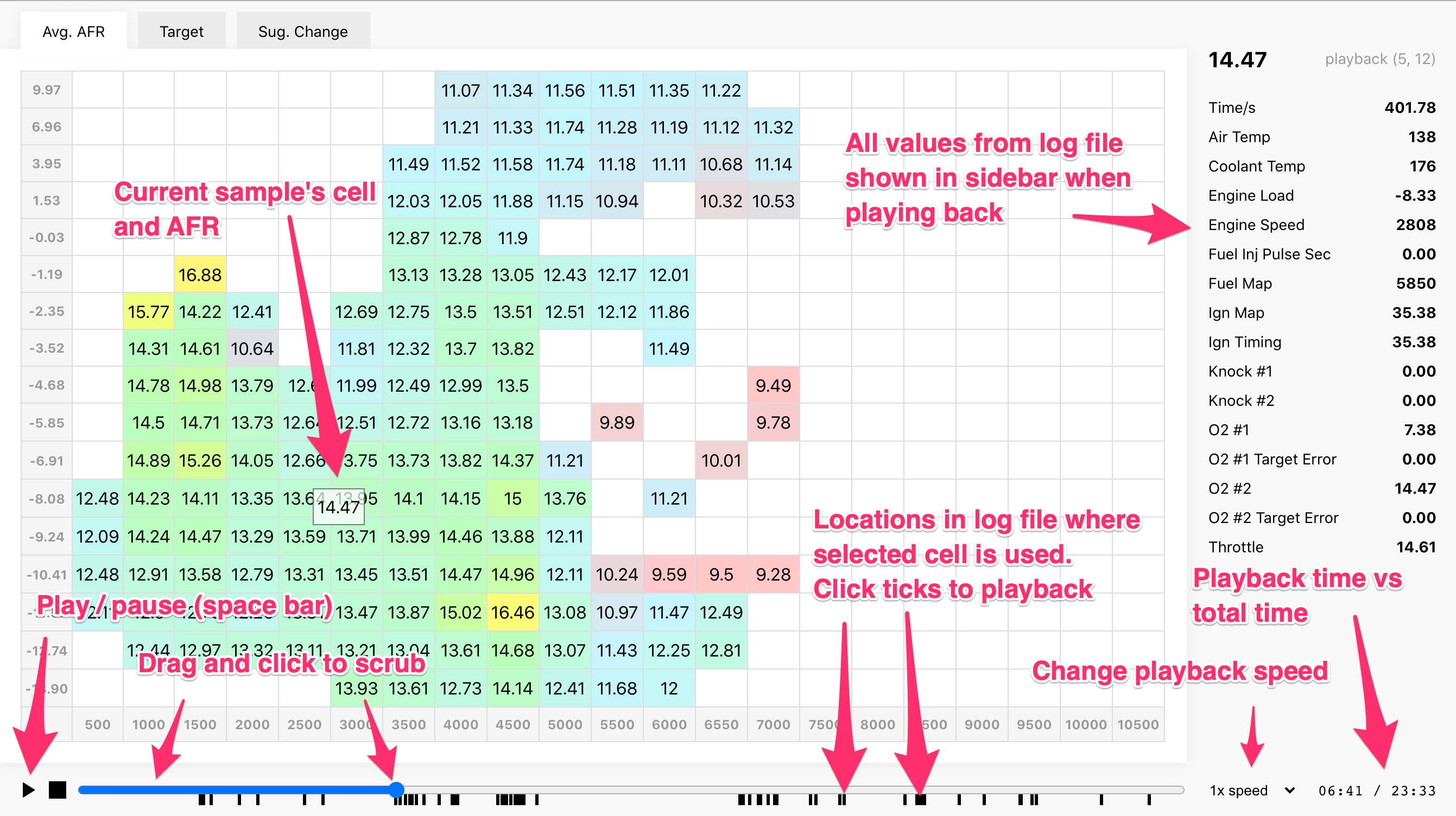
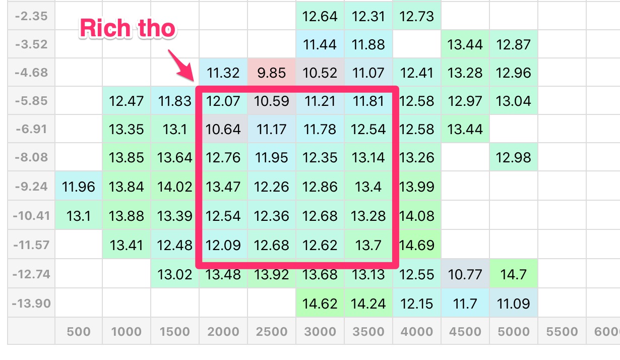
I made some progress on the data side of things. My biggest peeve with the car right now is it runs rich at cruising loads. The new wideband is part of the solution, but before I start tuning, I want to trust that the ECU is seeing accurate AFR.

The new wideband (AEM X-Series / LSU 4.9) doesn't always agree with the old wideband (Old AEM gauge / LSU 4.2). Sometimes it's like 1/2 a point different (idle mostly it seems; WOT is within .1 - .2). If they are different, the old one is richer. So whats the deal? Which is telling the truth: Old or new?

Some possibilities

1. They both are right. The old wideband is in the front bank and the new one is in the rear bank. Maybe the front bank generally runs richer?
2. The old sensor is on its way out. I don't know how old it is, and I'm not sure how they behave when they are going bad. It's not _that_ different tho...
3. Something is slightly weird where the ECU is reading the new sensor's analog out. Either it needs some gain adjust or my translation from linear func -> AEM software's table is off.

I'll have more info on the first two when I replace the front-bank sensor and gauge with another new LSU 4.9 controller. So the effort here was about validating the analog out in the 3rd possible issue.

AEM wideband gauges of old had this feature where you could unplug the o2 sensor and the gauge's analog out would read 14.7, or like 2.37 volts. So in the EMS software, you could adjust the gain or scale the table to make sure it read 14.7 AFR.

The new X-series controllers don't do this, an unplugged sensor is an error. How should I validate that the ECU is seeing the correct voltage? I emailed AEM and they were no help.

Going digital

I realized a couple things: The car has a CAN bus now! The X-Series controllers output CAN messages! Sweet!

After realizing this, the goal for verification was to get the controller's CAN messages onto the bus along with the ECU's, then read both the ECU's AFR out and the controller's AFR out at the same time. If they agree, yay, if not, adjust the gain value in the software til they agree.

The easiest way to read the CAN bus for both things turned out to be the RealDash app. An added benefit here was testing RealDash to see if it's a legit option for a navpod setup. Can I get it working at all? Whats the best way to permanently connect a device to the CAN bus? Are updates fast? How do I build and attach data to a custom gauge? Can I really do whatever I want with it CAN-wise?

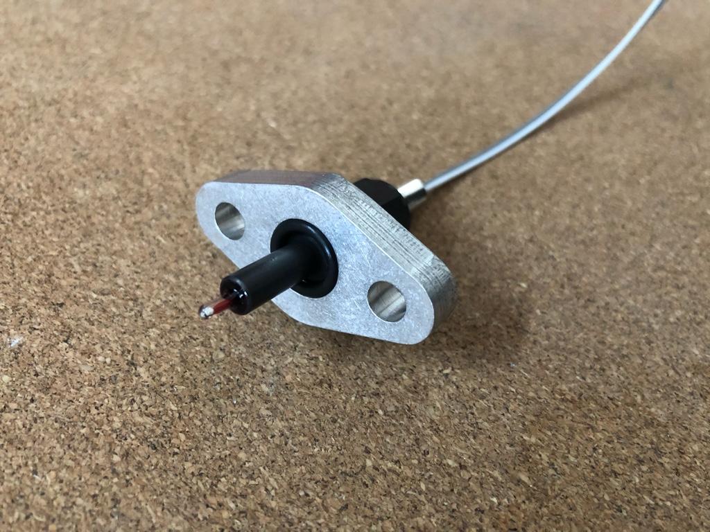
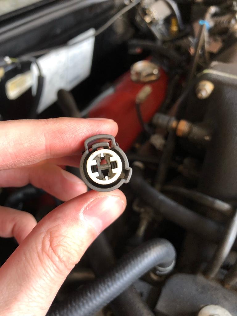
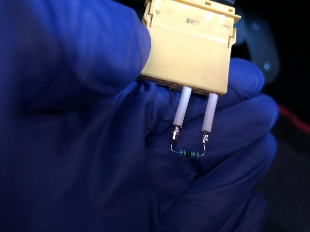
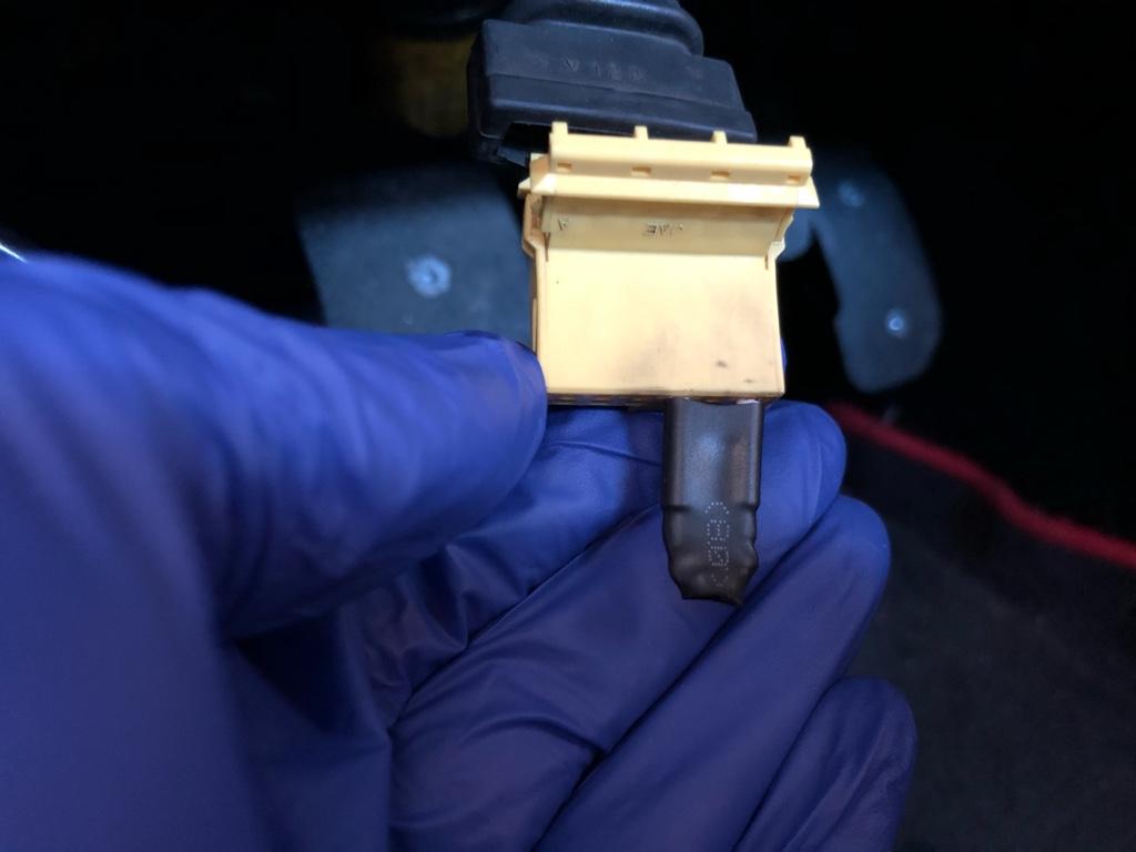
There are a couple ways to connect the CAN bus to a device. Seems like most common is an OBDLink MX+ device. It's bluetooth, but that seemed unnecessary for a permanent setup. I emailed RealDash and they pointed me to the SeeedStudio CAN analyzer. It's small, $24, and connects via USB.

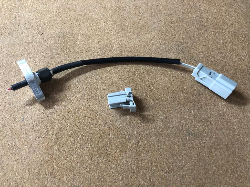
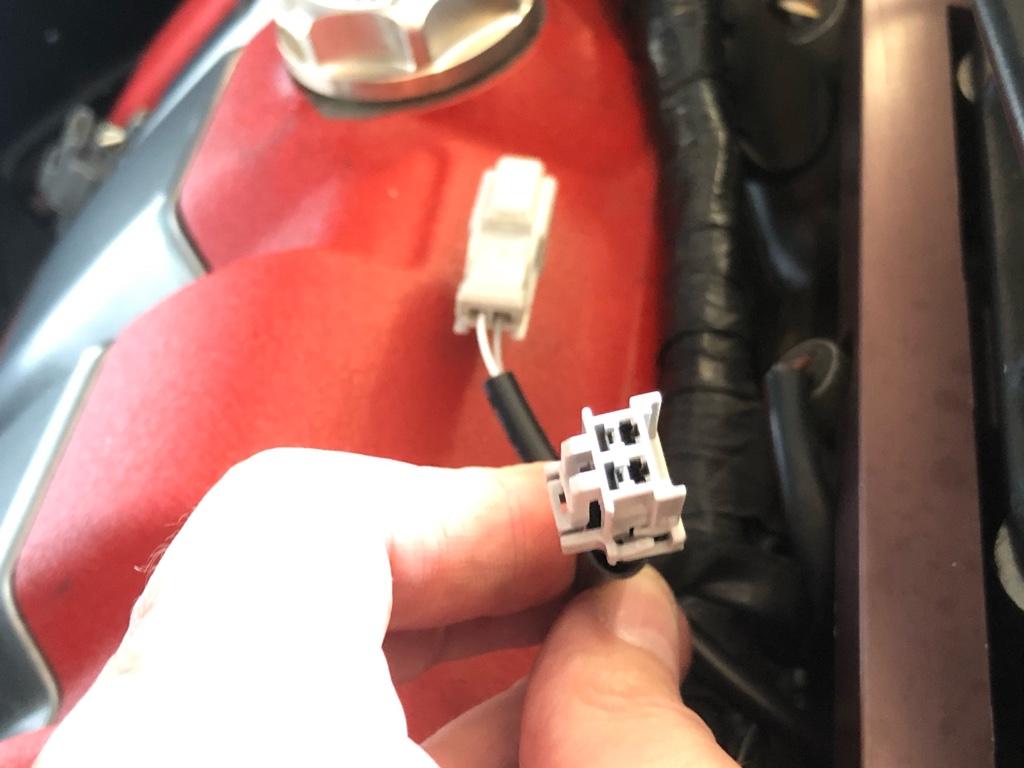
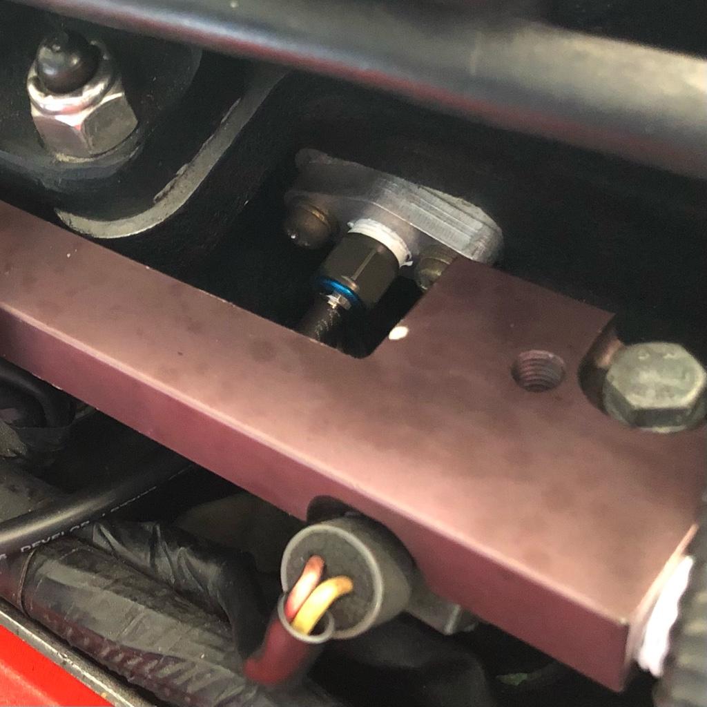
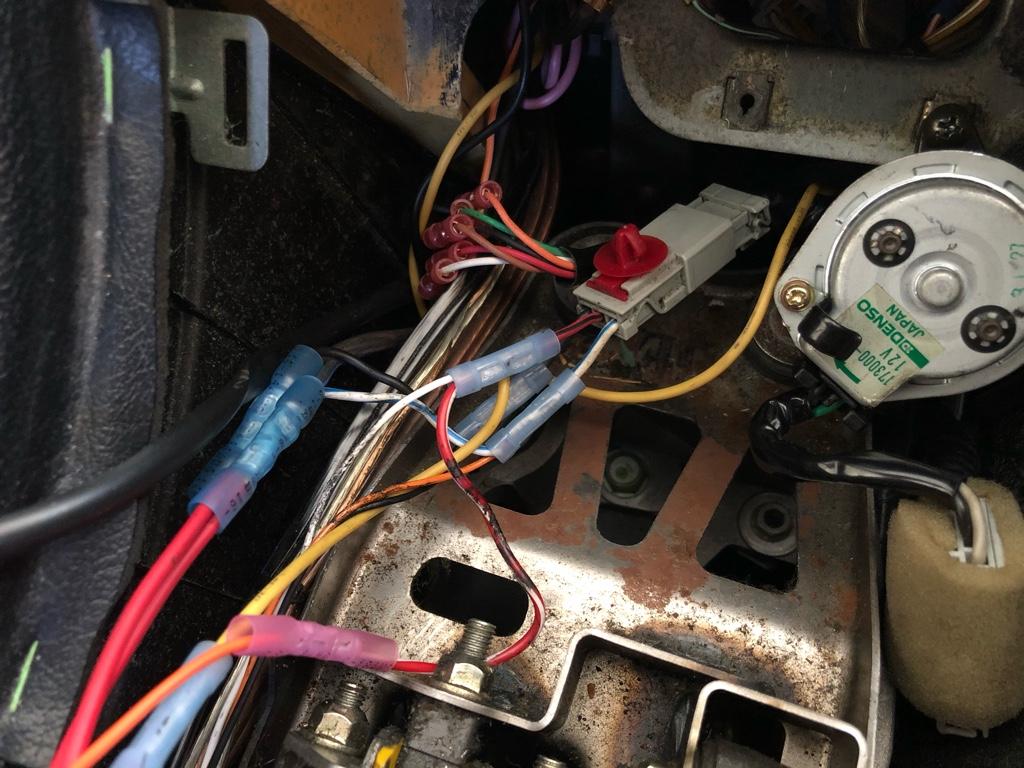
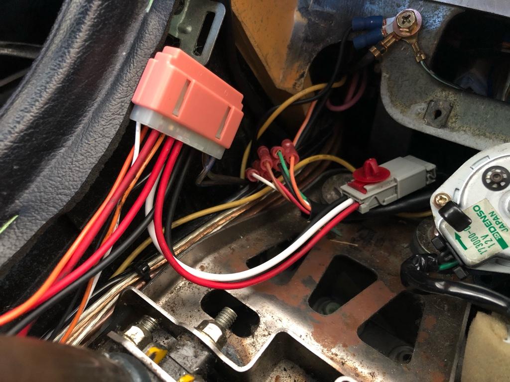
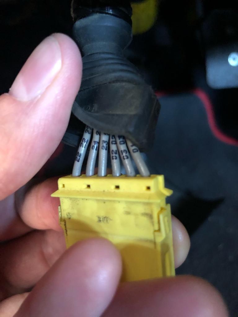
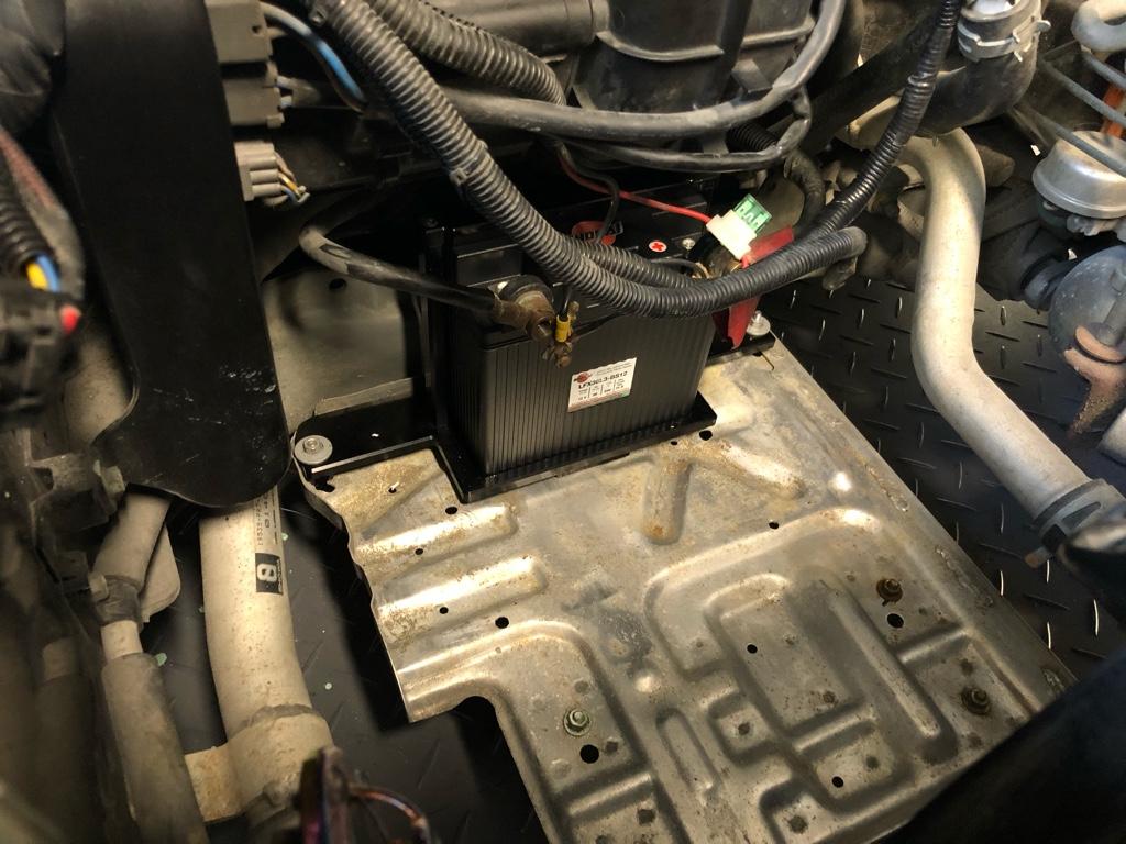
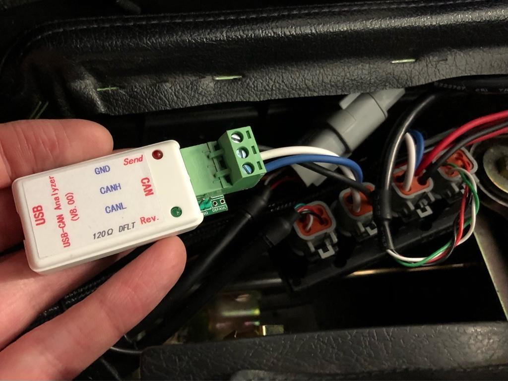
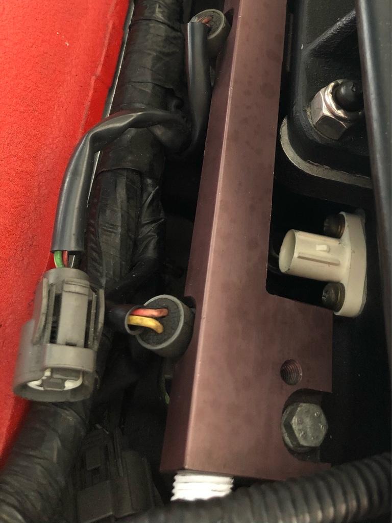
I ran the CAN wires into the engine bay (white and blue wires) and to the new controller. Originally I was going to do a temporary setup, but in the end decided to permanently wire it in. You can never have too much data, eh? Also the controller's CAN out has a couple flags indicating any controller or sensor errors which seems reasonable to show on the navpod.

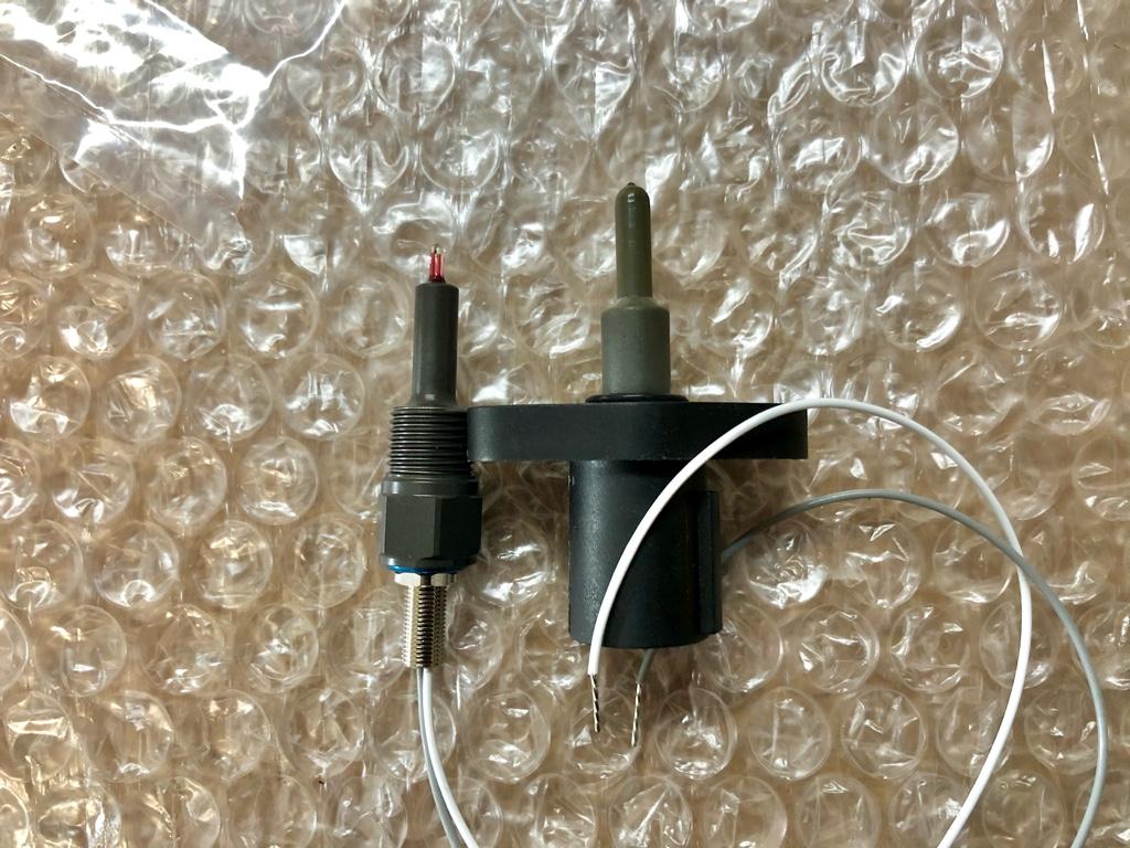
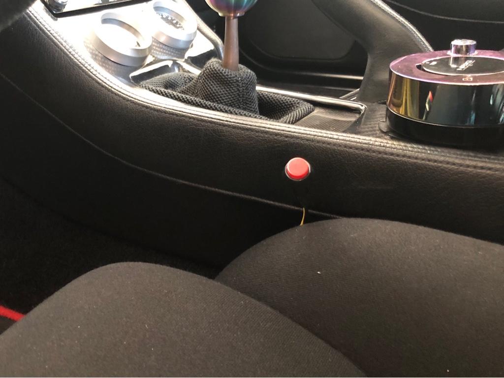
The SeeedStudio analyzer all wired in:

42d44e72a6ec3cc79b91b4fe15e27dbe.jpg


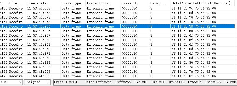
I hooked it up to a windows laptop, fiddled with some settings on the analyzer's software, and .... data! You can see the sensor is warming up as bytes 0 & 1 show as FF...

cd1c2c56d730706e25268af24b5ca0dc.jpg


I wrote up a custom XML file for the controller's CAN messages, loaded it into RealDash, then attached my new data points to a gauge in one of their example dashes:

5b1a394070389c4182f3893b907c2ce2.jpg


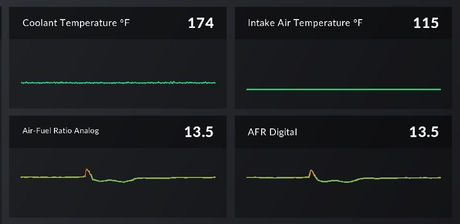
It works! The ECU (left AFR) matches the wideband CAN out (right AFR). You can see it follows even after a throttle blip. The controller's digital out seems to respond a little faster, but probably only by a couple milliseconds.

Now I'm ready to replace the old gauge with another controller...
 
Perhaps I can add some of my own findings with the wideband situation. Though, I'm afraid I may introduce more questions than answers.

I noticed my front bank is between approx 0.5-0.75 leaner. Though, on the front bank i'm using a Bosch wideband via a Zeitronix ZT2 sensor pack. The rear bank is what I have feeding into my HKS ECU and it's via their proprietary "Knock Amp" unit via a NTK (Denso?) wideband. I believe both sensors are not calibrated exactly the same (who knows...). I haven't been able to buy another Knock Amp so I have coverage for both banks with the same sensor because they simply don't sell it anymore and of the ones I find on Ebay it's basically a crapshoot. I did recently replaced the NTK sensor to a brand new replacement since it's been nearly 10yrs on the old one. Happy to report I didn't notice a difference in read out. If I was to guess maybe 0.2 +/-AFR variance but that's guessing. AFR is so variable as we know.

Another thing... I have trouble sometimes reading AFR because there are calibrations everywhere. For example, even HKS didn't have their ECU software calibrated to their own Knock Amp. It was a bit off there as well.

I have to ask my tuner if he remembers which bank tends to run leaner. If memory serves, I recall the rear bank runs a tad bit leaner on average. I went further to guess it's because of how the fuel rail is positioned - feeding the rear bank injectors last. This is why I run the HKS off the rear bank. Perhaps other folks with more experience can chime in re this.
 
Noted on the rear bank maybe running leaner. I read a bit around and it seems like other folks have reported a similar thing. The rail reason makes sense.

Any reason you don’t just update the widebands to newer controllers? Not sure what role the knock amps are playing with the wideband, but long as you got a couple adc inputs, you can use any controllers.

FWIW, the latest aem controllers are not expensive, come calibrated, and have a straight up linear analog out, so easy to get the calibration into the software. They have a way to open-air calibrate, but encourage you not to as they come calibrated.

I definitely trust the digital out from the new controller (and now the analog out cause verified!). I’m really curious how the same model in the front bank will behave. I have one on the way so we’ll see soon.

Calibration on the old wideband is probably another potential issue in the difference...
 
Any reason you don’t just update the widebands to newer controllers? Not sure what role the knock amps are playing with the wideband, but long as you got a couple adc inputs, you can use any controllers.
The main reason is because until I swap ECUs, the HKS (while ahead of time in my opinion) it's quite a closed system. It is still good for this old car because they control everything that connected to their unit. Their interface is even pre-calibrated to several of the OEM factory sensors like IAT and ECT, and the obvious ones like crank position. For example, while there are fine tuning calibration tables within the ECU, you're still limited to a set of pre-defined sensor selections in a pre-defined drop down list. Not sure if that makes sense. These are often not well documented as they wanted you to be tied at the hips with their dealer network. I suppose it reminds of the early Apple OS vs. the Windows or Linux.

If I had a newer car or if I was to do this all over again today I might go with a Haltech, Motec, or Link but for now, I don't see the investment in $$$ and time worth it for the marginal gains. I'm still pretty impressed with this ancient HKS F-Con VPro
 
Last edited:
I feel like every blogger ever: "sorry it's been so long since my last update". It's been a minute, but I've been tinkering! Mostly computering trying to understand everything that's going on.

1. I got realdash working for all the things I want to log except ignition timing. That included extending someone's realdash XML files for my own AEMNet + serial -> CAN + wideband setup. You can check out the files if you want. It's just running on the laptop for now, though. The medium term plan is still a navpod setup.
2. I fixed my dumb idle catch issue with the 'High Idle Condition' feature. It still drops below 800 sometimes when the revs drop from high up, but it doesn't feel like it's going to die.
3. Been logging a fair amount to understand how stuff moves and what all AEM's params are for (read below for fuel trim param nonsense).
4. Looking through all the trim tables to see how they're setup and what there are trims for. Now I have a decent mental model for what is happening for some scenario when I'm driving.
5. I've been working on something to help me analyze fuel params from the log files and tell me how much to adjust. I'll show y'all when it's further along. I find it hard to own a thing and not write code for it......

Temp Sensors

I read in a couple places that the built in honda temp sensor tables in the series 1 were off.

According to the manual our ECT and IAT sensors have the same temp -> resistance curve, but both tables are calibrated differently in my setup:

102702611-894be480-4219-11eb-98fd-cda9609e02f0.png


Are either of them right? Appears not.

I downloaded the infinity software and according to their tables:

* ECT table: seems correct < 150, above that it reads low (~20 deg at operating temp)
* IAT table: seems correct > 220, below that reads high (which jives with intuition)

I probably wont mess with the ECT table tbh cause a number of things depend on it that I don't want to mess with. But I really want the AIT to be correct. So I bought another sensor and I'll measure the curve myself.

ECT enrichment being a jerk

I dug into the all the fuel and ignition trims just to see how they were setup and to find any obvious issues.

The biggest thing I noticed was the coolant temp enrichment. It sort of never came out of enrichment. Here's the graph:

102702608-84873080-4219-11eb-973c-a252224b1ab4.png


With the current ECT calibration, the car reads right around 176deg at operating temp. When the car is moving on a not so warm day, it reads in the 160s. Check the graph, at 158 it was adding 15% fuel, then at 176, it was down to 0. The ECU will linear interpolate between table values, so it's adding somewhere in between 0 - 15% fuel when between 158 - 176 degrees depending on the temp.

While driving this shows as erratic richness. A 1 degree temp change in this range would change the enrichment by 0.8%. The coolant temp reading isn't crazy steady. Say it's fluctuating 10 deg or so around 170: 165 - 175, it'd add 1% fuel, then like 8%, then 3%, then 5%, etc. This could move the AFR by a point or more! I'm sure there is some smoothing algorithm going on in there, but I was seeing an AFR fluctuation.

I moved the curve down a bit--it didn't need 50% fuel right after startup--and to the left. Now it's 30% max, at 140 it's a couple percent and 0 at 158. Totally fixes the erratic afr.

Fuel Trims WTF

Understanding how all the logged trims behave has been interesting. If anyone has any experience with these, I'd love some insight. I emailed AEM and they were 0 help (as usual), emailed a couple people, asked on H-T, but so far I haven't had any luck.

Like did AEM ever supply a PDF describing each possible logged parameter's function / role? I cant find one, it's not in AEMPro (the in-app help articles don't come up), and AEM was like 'sorry, not supported anymore'.

Some of the trims are intuitive, e.g. accel and battery trims are 0 unless they are correcting, where they show their additive value. Cool. The rest?

Fuel Map [what is this? larger than expected at all times. Allegedly in microseconds]
Fuel (Fmod) [Seems like pre-trim fuel? how does it relate to Mod below]
Fuel (Mod) [^??]
Fuel Pulse [is this before or after trims? after some trims? Often not the same as inj #1 pulse]
Fuel Inj #01 Pulse [I assume this is final final pulse width]

Then there are all these `Fuel Trim (*)` params. They are all non-0 all the time, even when they should be 0. So far, they seem like maybe fuel map pulse width + their trim. When no corrections, they are all about the same. Say at idle, each would be around 1k. Maybe they get averaged or something? Max'd?

Fuel Trim (Ait) [non-0 even when no trim]
Fuel Trim (ALT) [non-0 even when no trim; table all 0s]
Fuel Trim (Baro) [non-0 even when no trim; table all 0s]
Fuel Trim (Start)[non-0 even when no trim]
Fuel Trim (TPS) [non-0 even when no trim; table all 0s]
Fuel Trim (Warm-up) [non-0 even when no trim]

Here's data from a couple log lines

Idle where the fuel table's interpolated value should be around 1.045ms. It's usually semi-makes sense when there are 0 trims.

Fuel Map: 5085 (Honestly, WTF is this?)
Fuel (Fmod): 1045
Fuel (Mod): 1040
Fuel Pulse: 1040
Fuel Inj #01 Pulse: 1570
Fuel Trim (Accel): 0 (this one does what I expect!)
Fuel Trim (Ait): 1045 (Should be no correction at current temp)
Fuel Trim (batt): 540

The values never 100% add up. For now I'm attributing that to when they're sampled. Like 'Fuel (Fmod)' is sampled, then calculated again, then 'Fuel (Mod)' is sampled. I can see this with some other values: something changes, say Accel trim (tip in), then there is a cascade of values in subsequent log lines that sort of make sense in context of that change.

Here I'm cruising at 2800rpm, trigger tip in trim:

Fuel Map: 5760
Fuel (Fmod): 2340 (Close to fuel table value, okay)
Fuel (Mod): 2350
Fuel Pulse: 2970
Fuel Inj #01 Pulse: 3475
Fuel Trim (Accel): 1500
Fuel Trim (Ait): 2330 (Should be no correction at current temp)
Fuel Trim (batt): 540

One where the Fmod and Mod dont match

Fuel Map: 5625
Fuel (Fmod): 1145
Fuel (Mod): 680
Fuel Pulse: 640
Fuel Inj #01 Pulse: 1190
Fuel Trim (Accel): 330
Fuel Trim (Ait): 1145 (Should be no correction at current temp)
Fuel Trim (batt): 540

If you got any insight, let me know!
 
Last edited:
I made some progress on having the ECU read a more accurate air temp. I'm now pretty confident it's accurate within ~5 deg F.

The builtin AEM resistance -> temp tables were wrong and there wasn't a super clear correct table to use. Some speculation on the internet, some ambiguous charts in the manual, some potentially wrong tables from AEM, etc. All no bueno, so I measured it on my own!

First off, rather than use the stock NSX sensor (part 37880-PE2-013), I bought the sensor Honda uses in most other cars (part 37880-P05-A00). It's the same dimensions and uses the same plug. White one is the Honda P05 sensor, black is the stock NSX:

304ce82542e5dd00ed9fc1e925cd12ae.jpg


And installed

48b9d3d7a5f7ea0b6c3b1525c17943e1.jpg


At first I was going to use the 2000-2005 S2000 sensor (part 37880-PCX-003) cause it has a metal tip. Seems like the metal tip would make for a faster response. But after reading a bunch on the s2ki forums, a number of people were switching to the Honda P05 sensor in an attempt to get a faster response. Okay. The P05 sensor is honestly probably no different than the NSX sensor, but it is newer, cheaper, more abundant, and who knows, maybe actually has a faster response (it's still seconds to stabilize tho).

The couple different sensors I looked into use a glass bead to detect temp. Honda IAT sensors are closed element--the glass bead is covered in plastic--for durability. Plastic is an insulator so it slows down sensing a temp change. Some other manufacturers make open element sensors which are supposed to have a faster response time, e.g. the popular GM sensor or AEM sensors.

Some s2k people were modifying their P05 sensor to make it have actual fast response by stripping the plastic from the tip to expose the sensor's glass bead, effectively making it open element. I figured with the 2nd sensor I could try this to see how things change...

Ok, so there were a few parts to making this right:

* Measuring the sensor resistance
* Measuring the AEM Series 1 ECU's pull-up resistor
* Using those two things to make a table I can put into the ECU

Measuring the IAT sensor

The sensor itself is just a variable resistor. Put an ohm meter across its 2 terminals and it'll read somewhere between 6k ohms (cold) and like 100 ohms (hothot). I needed to measure how many ohms it outputs for various temps. How to do this? Water on the stovetop did the job. Here is my very-solid-and-definitely-not-precarious setup.

8912be8af73d0adfe08e2cc053e52162.jpg


I used 2 different fancy meat thermometers (only one shown tho) to measure temp, and put the tips of all the things within ~3mm of each other.

3660ab3c97f675bcc4ae3a13e6f78bff.jpg


Then on the stove. It took a few measurements to work out how best to measure things. The process was: turn on the burner, let the thermometers rise 5 degrees F, turn off the burner, let the IAT sensor stabilize, then everything would be stable for 5-10 secs then start to slowly drop. Record the measurement during the 5-10 second stable window.

FWIW, it would take a few seconds to stabilize on even a 5 deg change. It would immediately start moving, but the thermometers got to the target temp way faster.

a19a22c385e22ed47baa389371dda8c7.jpg


And my measured table. It was actually pretty similar to a table mentioned a couple places on H-T and s2ki. But it is way off the tables in AEMPro and in the infinity tuner software for this sensor, glad I measured...

Ohms, Temp (F)
4100, 50
3570, 55
3100, 61
2950, 63
2880, 64
2480, 71
2320, 73
2100, 77
1965, 80
1937, 81
1900, 82
1650, 88
1400, 95
1250, 100
1200, 102
1185, 103
1060, 107
1050, 108
895, 115
810, 120
720, 126
660, 130
585, 136
520, 142
455, 149
405, 155
372, 160
328, 167
300, 172
284, 175
261, 180
235, 186
221, 190
210, 193
200, 197
193, 199
180, 202
175, 204
162, 209
158, 212


Measuring the pull-up resistor

Next step was getting the ECU's pull-up resistor value.

The ECU sees the temp as a voltage. To see volts, it's converting the IAT sensor's ohms to voltage by way of a voltage divider. The pull-up resistor is R1 in the link's diagram, IAT sensor is R2. To calculate the voltage for our volts -> temp table, we need to know this pull-up resistor value.

The IAT pull-up resistor value in the Series 1 ECU is not documented (of course). The internet thought it was either 2.2k or 1k, but I wanted to know for sure. So I needed to measure its value.

This was actually pretty easy: I found a resistor with a measured resistance of 1000 ohms and put it across the terminals on the IAT plug to simulate a 1k ohm temp reading. Then I logged the IAT voltage. It was a little noisy, fluctuating between 1.544v and 1.512v.

Backing that out, it looks like a 2.2k resistor. Mine is a little high, but very close to 2.2k.

The math:

pullupResistorValue = (refV * ohms / measuredV) - ohms

So

pullupResistorValue = (5v * 1000 / measuredV) - 1000

Which yields 2238ohms (1.544v) to 2306ohms (1.512v).

It's also possible the ref voltage in the divider wasn't exactly 5v. Like 4.9v vs 1.528v would give 2.2k. It's fine. There are so many places for error in this pathway...

Converting the ohms table -> voltage table

Ok, now with the ohms -> temp table and the pull-up value I can calculate the table for the ECU. I picked 2275ohms to generate the table cause it's a nice number in between the calculated resistance.

Basically, the formula is straight from the voltage divider page linked above:

volts = refVoltage * ohms / (ohms + pullupResistorValue)

The sort-of-tricky part is that it needs to fit into the voltage scale used by AEMPro. I wrote a little script that will take any ohms -> temp curve and convert it into a voltage -> temp table with the proper notches for the ECU. Check my work! Modify & use the script!

The final table:

Volts, Temp (F)
0.00, 284.00
0.16, 268.23
0.31, 215.67
0.47, 185.76
0.62, 168.06
0.78, 153.12
0.94, 141.37
1.09, 132.03
1.25, 123.40
1.40, 115.59
1.56, 108.79
1.72, 102.47
1.87, 96.32
2.03, 90.55
2.18, 85.30
2.34, 79.17
2.50, 73.79
2.65, 69.41
2.81, 63.44
2.96, 58.31
3.12, 51.99
3.28, 47.39
3.43, 41.29
3.59, 34.79
3.74, 26.62
3.90, 16.04
4.06, 5.46
4.21, -4.06
4.37, -5.55
4.52, -6.95
4.68, -8.44
4.84, -9.93
4.99, -11.00


For anyone who might come into this and need it: here is the table with the rated 2.2k pull-up resistor:

Volts, Temp (F)
0.00, 284.00
0.16, 270.78
0.31, 218.06
0.47, 187.92
0.62, 169.95
0.78, 154.80
0.94, 143.12
1.09, 133.70
1.25, 125.09
1.40, 117.29
1.56, 110.29
1.72, 103.97
1.87, 97.80
2.03, 91.98
2.18, 86.72
2.34, 81.04
2.50, 75.13
2.65, 70.98
2.81, 64.93
2.96, 59.74
3.12, 54.18
3.28, 48.69
3.43, 42.75
3.59, 36.17
3.74, 28.71
3.90, 17.93
4.06, 7.15
4.21, -2.97
4.37, -5.39
4.52, -6.82
4.68, -8.35
4.84, -9.89
4.99, -11.00


Further!

I'll run this setup for a while, but thinking maybe trying a couple things:

* Stripping the plastic to show the glass bead, how much faster is the response time?
* Maybe an AEM open element 1/8" NPT sensor. I'd make a flange out of some kind of plastic (delrin?) and use it in the stock location. It'd still have a potential for heat soak, but maybe I can insulate it enough to minimize?
 
Last edited:
I'm running an AEM IAT sensor tapped into the manifold with AEM Series 2. Are you stating that their setup file is wrong on that platform? If so, how far off? Nice work by the way. Keep this info coming.
 
The calibration is wrong for the stock Honda temp sensors. I’m sure it’s correct for the AEM sensor as it has a well documented scale.

It could be worth checking to see what temp sensor you have setup in the software and comparing the table against the table in the sensors pdf docs tho
 
It's been pretty rainy and cold lately, so my motivation for heading out in the garage and, say, replacing the AC compressor has been low. Instead, I've been spending time understanding the log files and how the car behaves in various situations.

Mostly, I'm trying to answer the questions: Exactly which cells in the fuel map are rich? How much should I adjust?

TLDR; To answer these questions I couldn't find any tools I liked, so I ended up writing my own log analyzer app. It's open source, works on Mac and Windows, and it can read any csv / tsv log file from any ECU with some configuration.

If you want to use it, let me know and I'll help you configure it for your setup.


104095853-f0275100-524d-11eb-9fbf-84236c52fc44.png


It has replay too, showing you the cell / AFR that's being used in the table, and all the related logged data in the in the sidebar. The ticks on the time scrubber show you all the places in the log file where the selected cell is used. (The readme has a gif, but tapatalk is crashing trying to render the gif, so this pic:)

104111837-fcd29600-529b-11eb-962d-77c11e9bea7c.jpg


* More details & code
* Download for both windows and mac

I tried using AEM's tools (AEMLog and AEMData), but found them lacking. They are pretty good at making & overlaying charts, which is useful fuel-wise for like a single WOT pull. But as far as I can tell, there isn't a way to work out what the average AFR for a cell is, or even what cell is being used.

Before the new app, I felt like I could glean more info by opening the logfile as a spreadsheet, which seemed kinda dumb.

FWIW, this isn't exactly my first rodeo here. A long time ago, my friends were putting B16s with junkyard turbo kits in their civics, and I had the B20 in my own civic running a B18 Integra ECU (PR4). There was no great (ahem, cheap) way to tune them--at the time, Hondata was really the only option, but was about the same price as an entire B16 swap. Crome was in its early stages, but only worked for OBD1 ECUs.

I wrote a ROM editor called BRE focused on OBD0 (mostly VTEC) ECUs so I could tune for the local cr3w. We'd spend a lot of time partial throttle tuning (still gotta get 30+mpg, you know?), and out of that came a bunch of log analyzer tools, autotune, etc.

Welllll, after logging a bunch of data with the NSX, I missed those tools, so I wrote this new app.

So far, it's been super helpful to identify problem areas, like basically the entirety of the cruising area:

104971772-a4d71600-59a4-11eb-88d8-5d68b48a0fe0.jpg


Now the goal is to pull fuel and get these areas closer inline with my targets. The first step is to get rid of the egregiously rich cells. Even averages around ~14 in the majority of that highlighted area would be huge. Then I'll be comfortable turning on the o2 feedback and having it work its magic. Also waiting on the 2nd extremely backordered wideband controller which hopefully will be here in feb.

The weather hasn't been great enough to test out my changes yet, but hopefully soon...
 
Last edited:
It's been pretty rainy and cold lately, so my motivation for heading out in the garage and, say, replacing the AC compressor has been low. Instead, I've been spending time understanding the log files and how the car behaves in various situations.

Mostly, I'm trying to answer the questions: Exactly which cells in the fuel map are rich? How much should I adjust?

TLDR; To answer these questions I couldn't find any tools I liked, so I ended up writing my own log analyzer app. It's open source, works on Mac and Windows, and it can read any csv / tsv log file from any ECU with some configuration.

If you want to use it, let me know and I'll help you configure it for your setup.


104095853-f0275100-524d-11eb-9fbf-84236c52fc44.png


It has replay too, showing you the cell / AFR that's being used in the table, and all the related logged data in the in the sidebar. The ticks on the time scrubber show you all the places in the log file where the selected cell is used. (The readme has a gif, but tapatalk is crashing trying to render the gif, so this pic:)

104111837-fcd29600-529b-11eb-962d-77c11e9bea7c.jpg


* More details & code
* Download for both windows and mac

I tried using AEM's tools (AEMLog and AEMData), but found them lacking. They are pretty good at making & overlaying charts, which is useful fuel-wise for like a single WOT pull. But as far as I can tell, there isn't a way to work out what the average AFR for a cell is, or even what cell is being used.

Before the new app, I felt like I could glean more info by opening the logfile as a spreadsheet, which seemed kinda dumb.

FWIW, this isn't exactly my first rodeo here. A long time ago, my friends were putting B16s with junkyard turbo kits in their civics, and I had the B20 in my own civic running a B18 Integra ECU (PR4). There was no great (ahem, cheap) way to tune them--at the time, Hondata was really the only option, but was about the same price as an entire B16 swap. Crome was in its early stages, but only worked for OBD1 ECUs.

I wrote a ROM editor called BRE focused on OBD0 (mostly VTEC) ECUs so I could tune for the local cr3w. We'd spend a lot of time partial throttle tuning (still gotta get 30+mpg, you know?), and out of that came a bunch of log analyzer tools, autotune, etc.

Welllll, after logging a bunch of data with the NSX, I missed those tools, so I wrote this new app.

So far, it's been super helpful to identify problem areas, like basically the entirety of the cruising area:

104971772-a4d71600-59a4-11eb-88d8-5d68b48a0fe0.jpg


Now the goal is to pull fuel and get these areas closer inline with my targets. The first step is to get rid of the egregiously rich cells. Even averages around ~14 in the majority of that highlighted area would be huge. Then I'll be comfortable turning on the o2 feedback and having it work its magic. Also waiting on the 2nd extremely backordered wideband controller which hopefully will be here in feb.

The weather hasn't been great enough to test out my changes yet, but hopefully soon...

Amazing work Bogle. You're definitely in the right car forum! [MENTION=33247]MotorMouth93[/MENTION], can we adapt this tool for our ECU logging? Does the TunerPro log file output as a CSV?
 
Amazing work Bogle. You're definitely in the right car forum! @MotorMouth93, can we adapt this tool for our ECU logging? Does the TunerPro log file output as a CSV?

Thanks! If you guys are interested, I'm definitely happy to help with the config for the factory ECU effort: help build it and help with understanding the knobs like weight thresholds, sample ignore expressions, etc. Also down to fix anything in the app to make it work well for your use case. There are probably assumptions I made that aren't totally universal, e.g. maybe the time column format + probably others. A sample log file and load/rpm scales would be all I need to generate a config.
 
Today was a pretty nice day so I took the car out with the adjusted fuel map. I adjusted and smoothed out the cruising part of the map based on the many log files I had been collecting.

Super happy to report it hovers around the rich side of stoich in all the right places! [emoji322] This might seem like a small improvement, but the rich cruising has been a thorn in my side the entire time I've owned the car.

106370655-e35bc180-6310-11eb-9543-1f7a12ff8b87.png


You can see there are a couple areas to be improved, but overall, it feels a lot better and drives like a damn accord.

e.g. The area top left in the 15's is when pulling away from a stop, I also pulled like a percent too much fuel at 3k rpm (-6 to -8psi), so I'll add some fuel there.

I'm so looking forward to getting the second wideband controller. It's annoyingly backordered. I think I ordered it in ~November....

When I do get it, it will unlock a bunch of projects: I'll be able to turn on o2 feedback (per bank!), then I'll be able to remove of the old wideband and its a-pillar gauge. With an extra space in the a-pillar, I can reshuffle all the gauges to make room for the navpod, install the navpod and live in the damn future.

Other than that, I have a couple other projects in progress:

* I still need to do the AC compressor. I have all the parts!
* I found a new aftermarket fast air temp sensor (rife sensors) I'm almost ready to install
* Working on a wheel project that will take a couple months
 
Last edited:
I installed a new air temp sensor yesterday. After tinkering with the OEM sensor and doing a bunch of research, I was curious about open element sensors. Would an open-element sensor be waaay faster to register temp changes than an OEM sensor?

What even is an open-element sensor? It's a temp sensor with the actual temp sensor part (thermistor) exposed. The stock IAT sensor has its thermistor covered in plastic. Generally the open-element sensors are faster to see temp changes and stabilize, but are more fragile. I'm sure longevity was the reason Honda used an insulated sensor...

There are a number of open-element sensors out there, the most popular one probably being the GM sensor (~$60), followed by the AEM sensor (~$60), then a long tail of fancy $$$$ race car sensors like the T1 "fast acting" sensor at $150+.


The Sensor

In my research, I stumbled onto this company called Rife sensors who recently released a new air temp sensor. It is not expensive ($50) and they claim it's better than the GM sensor in both accuracy and response time.

I emailed them and asked them a bunch of questions, mainly about heat soak and response time. They were super nice and answered all of my questions:

We addressed heat soak on this sensor when we designed it. We tackled it in several ways. 1st we extended the sensing element out further in the airstream, second, we use a very low mass sensing element for faster response on both temp rise and fall. Third, the sensor element is in shrouded, so it sees better airflow and isn’t surrounded by a heated mass (cage). Also, the sensing element is thermally isolated from the body along its entire length.

As to the thermal time constant, I am hesitant to give on because some people think they can use it to calculate a response time when installation has a much bigger impact than they would want to admit. That being said the ttc is ~1s in 5m/s air

Makes sense that the flow volume has a huge effect on the sensor's reaction time.

He told me the the stock location was not optimal by being basically over only one cylinder's "runner". An optimal location would be somewhere after the SC that saw full flow. For a street car it's probably fine though.

I really liked that this sensor stuck out into the air stream more than any of the others I looked at, even the schmancy race car sensors. So I figured I'd give it a shot. I went for the Lo-AT sensor (-30F to 335F).

Here it is next to the OEM sensor. It is about 1/4" stubbier than the OEM sensor, but still longer than the other options. You can see the exposed thermistor at the tip, it's a little glass bead:

c0e8e42b86d3f49cdf6dd7f68d4c5c02.jpg


Mounting Flange

Next up was a mounting flange. I don't think anyone makes an 1/8 NPT flange for the stock location. My dad has a machine shop, so the plan was to have him make me one on the mill.

Ideally it would be made out of something insulating. But fancy plastic is expensive / maybe hard to machine (e.g. phenolic), I just wanted to get this working, and the Rife sensors dude told me mounting it in aluminum is fine. My dad has mountains of scrap aluminum, so I figured I'd start with that instead of sending him a $60 piece of PEI only for this to maybe not work at all.

Here is the sensor in the new flange (1/4" 6061 FWIW). We recessed it for an 011 size o-ring, which is super close to the stock o-ring size. I learned a lot about different o-ring materials; it seemed like Viton was The Move due to its high temp range and oil resistance, so Viton was what I ended up with.

aaa2af057509adcb90a71df22412b4b2.jpg


Connector

Last step up was the connector. Ideally I'd use the stock plug on the harness side and not cut any wires. The stock plug is a female Sumitomo HW 090 VTEC pressure switch plug. But they never made a male counterpart: the male plugs are the sensor itself.

I emailed Joe from CycleTerminal and he told me that the HD 090 plugs used the same terminals. The downside is that they are unsealed. Oh well. I'll use the unsealed connector for a while. In a few months provided this goes well, I'll probably bite the bullet, cut the harness, and install a sealed DTM connector or something. If you have better ideas, let me know!

The stock HW 090 plug:

8c50652a87c56699e8efa177c319fe53.jpg


The sensor with the unsealed HD 090 on it:

8e7491d80cbe75c60e3eddf2c9b31c62.jpg


The HD 090 plug installed on the stock terminals

1b2d5a8c84be759f6ac5dc7be8d336aa.jpg


Installed!

1f2a369545581c722d6aa9fb0c024c64.jpg


It works! It seals! My calibration table seems to be right!

Ok, charts or it didn't happen. Overall the new sensor is faster and seems to be a little less noisy--I was able to notice less steady-state fluctuation pretty immediately just driving around. The ECT sensor is way noisy, I wonder if an aftermarket sensor would be an improvement....

Admittedly this isn't so scientific, but you can see the OEM sensor peak after the load spike, then take a little longer to stabilize. Also, the OEM sensor didn't have enough time to really see the full temp spike before the temp started decreasing. I noticed this when measuring the OEM sensor too: it would immediately start moving in the direction of a temp change, but would take like 10 seconds to stabilize to the actual temp. (The OEM sensor's thermal time constant is 15 seconds!)

OEM:

107155995-93908200-6930-11eb-97cf-2097a5297d67.jpg


Rife sensor:

107156001-95f2dc00-6930-11eb-8298-95fcb86319cb.jpg
 
Last edited:
So I've been doing more tuning. Maybe not so interesting, but imma tell you anyway. :)

I did a couple more passes on the main fuel map and have been able to clean it way up: no holes, everything is smooth, low-mid 14s consistently < -7psi & ~4k, 12s and 13s before boost depending on situation, then not touching the boost bits cause they are fine. It's been pretty straightforward, and the car feels really good.

The one thing that still feels a little messy was tip-in / accel fuel, so I moved into tuning it.

I now think I mostly understand how it all fits together, but I’m still not done, and it’s been a pain for a couple reasons:

* My TPS signal seems extremely noisy (if you have data on yours, please share!)
* AEM's software & docs: there are a couple really confusing options / params that took a while to figure out (I _think_ I understand them anyway)

I started digging into it cause there was a lean then rich condition on tip in. The trim felt a little late, then it usually ended up adding too much fuel.

108635028-b42d0180-7431-11eb-9898-fcdf7deaa40b.jpg


I read AEMs docs and a whole bunch of forum posts. Beyond a handful of tables (which _do_ make sense, yay!), there are 4 settings (and my OG values):

* Accel dTPS Trigger: 10
* Accel TP Sensitivity: 69.92
* Accel Limit: 80
* Accel Pump Sustain: 35.16

The most important are the first 2:

"Accel dTPS Trigger" is billed as:

Units: %. When the change in TPS (dTP) exceeds this value, Fuel Trim (Accel) can be added. This acts as a minimum TPS change threshold for Fuel Trim (Accel).

Intuitively I figured this is the min change in TPS required to apply the accel fuel trim. Makes sense, I thought. It's % they said, relates to Accel dTPS they said...

And "Accel TP Sensitivity":

Filters the TPS input and the effect can be viewed in TPS Filtered. It reduces the fault triggering for very sensitive throttle changes. A value of 0% completely kills the accel pump function. A value of 100% is essential no filter and creates a hyper/useless pump. A typical value is 75%-90%. Set this value while the engine is OFF and watching the Accel dTPS and Accel dTPS Latched parameters.

For this one I thought LESS sensitivity would mean MORE smoothing, and 100% would essentially follow the raw TPS signal. This especially made sense because a couple forum posts, even one by AEM_NS said the goal is to get the sensitivity as high as you can without trim oscillation.

It seemed like my sensitivity was on the low side, and based on all I'd read and was causing the late reaction--most people's values were in the 90 range, mine was 70.

So I bumped the sensitivity and spent an hour in the car driving and adjusting the tables. I got it to a pretty decent place on an actual TPS change, but I could do nothing to get it to Chill the F out when no throttle change. I was afraid of the trigger threshold at the time cause it never did what I wanted and focused on the sensitivity. A reasonable example:

108629073-0e6a9a00-7413-11eb-80a2-1495599b0848.jpg


Note the bottom pink line. It's the delta TPS and it's basically always fluctuating between 0% and 5% unless TPS is 0. Remember those settings above?

Wellll, a couple things

* My trigger threshold is 10, which is more than 5, but the WTFs in that chart are pointing at an applied fuel trim when delta TPS is max 5.
* No matter what I set the sensitivity to (I tried >= 50), the delta TPS still fluctuates

Another example while cruising after adjusting some things, you can see the accel trim totally ruining my sweet mid-14s cruise tune.

108629431-ae74f300-7414-11eb-8bac-e877f28630e9.jpg

My Dumb TPS

A quick aside. It seems a lot of this would be mitigated if my TPS signal was less noisy. It's always a 3 or 4% fluctuation.

Is that normal? Anyone else logging their TPS signal and seeing better/worse/same? None of the other sensors are this noisy, e.g. map is pretty clean.

My gut says it's the sensor, but it could be electrical noise. Alternator? Wouldn't it affect other sensors? I guess it could be a bad connection somewhere in the harness or at the connector. Vibration on the sensor?

I measured the sensor with an analog ohm meter and it was smooth through the range. Tapping the sensor with a screwdriver would make it jump, but not by tons. The signal is not as noisy from the ECU with the car off, but it also doesn't show the same values...

I guess after typing all this out it seems like an electrical problem...

I have a big bore TB coming from SoS in an attempt to try another OE TPS, but it's on 6-8 week backorder.


Path to Understanding

Yesterday I spent some time revving the car in the driveway like a good neighbor, trying to understand the trigger and sensitivity.

Looks like the higher the sensitivity, the MORE smoothing happens, but also the faster reacting. I don't really understand how it'd be faster to react with more smoothing, but one thing I read on this AEM thread did start to make sense:

Accel dTPS is the difference between Throttle and TPS Filtered

I guess this is why the delta TPS is so noisy? Cause it's following the raw signal noise? I guess also thats why a 0 sensitivity has no effect: there is no change; TPS - TPS = 0.

Mini rant: if true, that seems like the a dumb algorithm to determine delta. Why compare this super noisy signal to the smoothed version of itself? Wouldn't you keep a couple smoothed samples around and diff the current smoothed sample with a couple old ones? Response time maybe?

Ok on to the trigger. I did some hacky stuff in the tables to get dTPS latched to show me the real % change it's using for the trim. Turns out it was double the logged Accel dTPS value. I mean roughly. Good enough for my mental model and looked to be consistent.

But that's only 7 or 8, my trigger was set to 10, and it's still adding fuel.

I noticed, the Accel dTPS Trim table's alleged % column goes to 128... hmmm. Is the trigger setting 0 - 255? OMG YES. Could it be.... I dumped the raw values for one of the logs, and it looked like the Accel dTPS percentage value was `raw / 2.55`.

Trigger is probably the raw value: 0-100% over a single byte: 0-255. Let's check:

I set the trigger to 12 ... still adds fuel ... 13 ... barely fuel ... 14 ... NO TRIM unless actual TPS change. 14 / 2.55 = 5.5 actual %. None of the steady state deltas showed over 5 so, makes sense. Yay!

Here's some driveway revving when I finally started understanding. You can see how noisy the TPS is. This is sensitivity 90. TPS Filtered is pretty smooth.

108634685-8fd02580-742f-11eb-8dcd-c8a086cfe5d0.jpg


And at sensitivity 70, the filtered TPS has more noise:


108634680-8cd53500-742f-11eb-8fa9-ac46d6c49228.jpg


Moar

I'm not done with this yet. I didn't actually get to drive it yesterday. I’ll need to do another pass on the accel fuel and make sure my changes are still reasonable. I also probably need to make sure the main map isn't lean or in a weird state due to random cruising accel trim with the old settings...

I didn't drive it because during this whole process, I think I nuked the new o2 sensor. The car had been sitting for a week, I turned the key to IGN then spent a lot of time checking the TPS signal in the logger and messing with stuff before starting the car.

From what I read, it seems I probably got some condensation on it when it was hot. The wideband had been heating while in the IGN position, probably up to temp when I actually started the car, then splash + broken. I guess this is common, and it should only be heating when the car is running. Now I know, if it’s been sitting for overnight, just start it right up! I should have a new sensor today.
 
Last edited:
Totally geeking out on this post. Love the detail! You should chime in on our Honda ECU tuning thread.
 
Yeah I’ll take a look and see if there’s anywhere I can help. I did a fair amount of reverse engineering on the obd0 vtec ecus, and wrote a bunch of features for them (boost code, alpha n support, launch control garbage, etc...) but you guys might be beyond my experience with this ecu.

Are you guys logging tps? Is it crazy noisy? Am I crazy? Is mine way over spec? Seems really absurdly noisy
 
We last left off where I didn't drive the car because the wideband stopped working. That lead to some debugging, a little rewiring, then snowballed into other interior & wiring projects. Here’s a selection of the stuff I got done. I’ll post about other little projects soon.

Wideband

So the wideband. The day I was impressing my neighbors by revving in the driveway, the wideband that is wired into the ECU stopped registering a legit value. It always showed 0 volts.

Initially, I thought I burned the sensor out, so I bought another one, installed it, and .... same thing.

The controller has some status lights on it--it was fast-blinking green which means "sensor heating". The problem is that it never came out of this heating mode. The sensor was getting hot to the touch but I guess not to the satisfaction of the controller.

I emailed AEM and they told me it was probably user error: they had seen this before when there was spotty 12v powering the thing. I hooked the controller directly to the battery and ... it worked as expected. But but my wiring was perfect! What could be the problem?

I pulled apart the interior, did some tests and it seemed likely that the many jank butt connectors were probably the culprit. Look at this nest:

44a320c6e9f8ac78ed4dd4f8bbc0dca7.jpg


Right after I finished wiring in the wideband power, I bought a connector (HM 090) that acts like a distribution block / bus bar. My goal was to eventually replace this nest. The pink cap has 3 bus bars / circuits, I'd use it for ACC 12v, ground, and illum 12v from the cigarette lighter circuit.

111925386-edbf4f80-8a65-11eb-99e9-792445a18606.jpg


Now was the time, even if it didn't fix the power issue. I re-pinned the cigarette lighter connector too.

3739a57ac5d291fc441d797bdea53e1a.jpg


Fired up the car, and the wideband was back to normal. Power issue fixed!

Horn

When I got the car, I was afraid to push this red button that was randomly coming out of the carpet:

a509d1517f5ed23a4e94b95bfc3fcc8f.jpg


I finally mustered up the courage.....turns out it was the horn. Good job previous owner, super clean. Well, I traced it all back and removed the related wires from the console back to the under-dash harness. It's not running through the SRS harness. Not sure exactly what it's tapped into, but it uses the stock relay. A job for another time.

Another problem was that the OG Sparco button wouldn't stay in the wheel. A Type-S button was the ideal, but real Type-S buttons are baller, so I bought an ebay copy. It's actually pretty nice.

ba71c0a297cfd14600333ea71f84ab99.jpg


8077e9112285f7783f9c1be6820c4c34.jpg


The hub was already grounded, so I just needed to run the power wire to the back of the quick release hub.

51ca8e15c3a72cbd6a5e8b6f33194ff4.jpg


Yay, real horn!

SRS Light

I spent a lot more time on this than I'd like to admit, reading in the electrical supplement, trying to find a male connector, making pins to fit the harness. My car didn't have the cable reel, so just this plug (C704).

5c834f2f72ac452280e175e68ca61108.jpg


From the left to right

1: (22) 12v / horn (ground to honk, beep beep)
2: (24) Cruise Resume (momentary connect to pin 1 to resume)
3: (23) Cruise Set (momentary connect to pin 1 to set)
4: (02) Airbag 1
5: (03) ??? (seems like not connected to anything)
6: (01) Airbag 2

The trick is to tell the SRS computer that the airbag is "connected" by jumping pin 4 (02) and 6 (01).

I haven't found that male SRS connector yet, so I made some pins out of wires that fit the terminals. I just tinned the wires with the soldering iron until they fit snug in the SRS connector. FWIW, that was .062" - .065" in dia. Some threads on prime said to use a low resistance resistor to properly mimic the airbag rather than a straight up jumper wire, so I ended up with a 10 ohm resistor cause I had it.

284e3d6bd8f19d97f11814eae5eeb607.jpg


Then I put a piece of shrink tube over the whole thing:

59776922c6c65b1845c39389ea2f07cc.jpg


Buuut, the light was still on. After more troubleshooting, turns out the previous owner removed the SRS fuse. Put a 10 amp in there and, no more SRS light!

More Accel Tuning

I was able to drive the car a bunch yesterday and did a few more passes on accel fuel. I'll post more about it a little later.

I focused on the sensitivity, threshold, and decay settings, aiming to nail down the "when": making sure it corrects at the right times. It's now overcompensating (rich) here and there, but it's covering the lean condition and I'm to a point where I can't do much until I get the new TB / TPS. It's working and feels pretty ok, but I'm basically using a couple workarounds for the TPS being so noisy. I'm hopeful the new TPS will be less noisy, which will change my approach quite a bit.
 
Last edited:
A couple new non-tuning related things

Lightweight Battery

A KC machine (kinetic) battery box for Shorai batteries came up for sale in the FS forum and I couldn't pass it up. It's a really nice piece which I failed to take a picture of. It works with the Shorai LFX36L3-BS12 battery. The battery seems a little controversial as some folks had problems with longevity, and it's not cheap.

But it is light!

* Old setup was 33.5 lbs
* New setup is 6.5 lbs
* Savings: 27 lbs

First thing I wanted to do was clean up the battery tray. I figured this would be pretty easy, but after an hour of multiple sonax passes + simple green & wirebrush scrubbing, it still wasn't that clean. Before:

4bc0af5b13a986c5d0c9a094539209f6.jpg


And here it is after: better, but doesn't look "clean". It's pretty pitted from 30 years of lead-acid batteries. If anyone has a pretty clean one for sale for non-crazy money, I'm interested...

56d0386c6a88382cc71c49094cf75cfa.jpg


And installed.

75ac320e2550ce793e9b339640583998.jpg


Hopefully it lasts a few years. The car is in a mild climate and I'll have it on the Shorai charger in store mode most of the time.


Brake Pads

It was unclear what pads the car came with and the fronts were probably 50%, so I wanted to change them out to a known quantity. The rears were probably 95%+ and there was no wear on the rear rotors.

The big decision here was: which pads. This isn't a track car, so I just needed street performance pads. At best I wanted a set of pads that would be fine for the eventual track day here and there, but the vast majority of their time would be stuck behind SUVs on the street.

It seems there aren't really any (good) dual-duty pads out there. In an ideal world they'd be low dust, easy on the (very expensive front) rotors, and trackable. But as far as I can tell, that pad doesn't exist. Also nearly every pad I looked into had really mixed reviews: 50% glowing reviews and 50% "omg don't buy them, they do X really poorly".

In the end it really came down to 2 pads: Stoptech 309 or something in the carbotech line.

The Stoptech 309s are the pads that come with a Stoptech BBK. They are super cheap ($100 / end) and seemed like a good in-between pad. People (novices) track them, and anecdotal evidence says they aren't crazy dusty or hard on rotors.

But Carbotech came up over and over with virtually no negative forum posts / reviews for any pad I looked into. I ended up with their street pads: the 1521 compound ("Bobcat"?).

For the 1521s, Carbotech explicitly says "do not use on the track", but I was sold by a few things:

* Dust is non corrosive and easy to clean
* They are apparently low dust
* Supposedly easy on rotors

The thing I liked the most, though, is that all their pads are interchangeable without re-bedding. So I could get some XP8s if wanted to go to the track, swap them out and go, then get home and go back to the 1521s. The reality is that I'd probably take these 1521's to a trackday or 2 until they were a bottleneck, then get the XP8s. I read a number of threads with folks in heavier cars (Corvettes, Cadillac CTS) using them on the track and they were fine for their first couple HPDEs.

The new pads

5a60ced24ddce01e6ce317b5187a7019.jpg


One thing that was difficult was getting the right pad shape / PN for the brembo calipers. They are 4 piston GT calipers sometimes called "Lotus A.C.F." calipers or "GT2" calipers depending on where you look. They look like this:

113520480-3851c900-9548-11eb-98cb-3615d2040571.jpeg


Apparently they are the D592 or D1053 shape, but Carbotech has 3 part numbers for these shapes. I emailed back and forth with them and turns out the only difference is the thickness of the pad (with backing plate).

CT592-1521: .570 (14.5mm)
CT592A-1521: .670 (17mm)
CT1053-1521: .600 (15.3mm)

I measured caliper to rotor, and I had 16mm absolute max. I sprung for the CT592-1521 to be sure I didnt have any issues. They just fit, I think the extra mm would have been too much.

e77c19ed6a93add914640497088882e3.jpg


Here's the old pads. You all have seen a brake job before so I didn't really take any pics other than this!

f7abfde988a5d6bc223bf4456170368f.jpg


Took them out for some street bedding on my favorite road around here. The pads didn't come with bedding instructions, and the instructions on the website were for on-track bedding of their track pads. I followed this, which seems pretty similar to how I've always done it with other cars/pads: https://new.minimania.com/CARBOTECH_Brake_Pad_Bedding_In_Process

* Brake from 60mph down to 30mph about 4-6 times
* Then let your brakes cool for about 2-3 minutes while driving
* Repeat step # 1
* Allow the brake pads and discs to cool down to ambient temperature (about 30 minutes or more)

Now they feel good! I was never very hard on the brakes with the old pads, so I can't comment on the real differences between them. One thing I learned is that the ABS is not hooked up. Once bedded, it was pretty easy to overwhelm my old, hard direzzas.

I did some digging and the ABS pressure switch connector is disconnected + jumpered. I bet the ABS was medium busted like seems to be the norm with these older units, and they just disconnected it. An upgrade is on the list, but probably next year...
 
Last edited:
funny those old pads have no markings on the back plate. The material side reminded me of ferrodo..
 
The battery support bracket would turn out well with some media blasting if you wanted. I think it looks good enough already though, it's gonna get covered in dirt over time anyways ;).

Good choice on the low dust pads, I sprang for EBC yellow this time instead of the reds and the amount they dust isn't worth it for mostly street use. I'll be upgrading my ABS soon too, mine works ok at the moment but overflowed once and it's not really worth trying to fix IMO.
 
You’re right, I should have looked into getting it blasted. There are probably local places with a media blaster. Maybe I’ll do that down the line. It is super pitted and some of the holes have been eaten away a little where the stock battery was, though, so that would still be there. But I guess not a concern as it’s all on the tray and the extruded tubes have no corrosion (other than normal alum white oxidation). I was thinking it’d be nice to get a clean one and have it powder coated black. For now it holds the battery off the ground, so it’s fine.

Yeah the old pads dusted quite a bit, hopefully these are better. Literally one short drive on the old pads and the wheels would be coated. Too bad your shiny RG3s are getting dirty! Hopefully the dust is easy to clean. Sonax is magic (on wheels, anyway)
 
Back
Top