
[emoji106] champ white and mag blue are up there for me. There’s like 5 of them I like lol
-
Protip: Profile posts are public! Use Conversations to message other members privately. Everyone can see the content of a profile post.
You are using an out of date browser. It may not display this or other websites correctly.
You should upgrade or use an alternative browser.
You should upgrade or use an alternative browser.
bogle's 1991 mild build thread
- Thread starter bogle
- Start date
Nice work on the AC!
Champ white or the gold for me...
Champ white or the gold for me...
Nice work on the AC!
Champ white or the gold for me...
Thanks! It was a production and I’m glad to be past it. Now i can focus on more performance oriented things
Noted on the colors. The gold does look quite good against the black
mag blue would look killer!
mag blue would look killer!
Thanks! Tis a dilemma
Great work on all the A/C stuff, glad my post helped too.
I'm really coming around to the squared tire width fitment thing in your pic below, I didn't really get it but it just looks so right. My next set of tires won't be the 205 width Indy 500's up front..
I've still got a JDM front license plate on my list of things to do, jelly...
Formula silver or the gold (surprise) looks the best to me. The silver is really classy looking and draws attention to the wheels without being too overbearing. Black & gold goes without saying")
I'm really coming around to the squared tire width fitment thing in your pic below, I didn't really get it but it just looks so right. My next set of tires won't be the 205 width Indy 500's up front..
I've still got a JDM front license plate on my list of things to do, jelly...
Formula silver or the gold (surprise) looks the best to me. The silver is really classy looking and draws attention to the wheels without being too overbearing. Black & gold goes without saying


+1 love the meats
Great work on all the A/C stuff, glad my post helped too.
I'm really coming around to the squared tire width fitment thing in your pic below, I didn't really get it but it just looks so right. My next set of tires won't be the 205 width Indy 500's up front..
I've still got a JDM front license plate on my list of things to do, jelly...
Formula silver or the gold (surprise) looks the best to me. The silver is really classy looking and draws attention to the wheels without being too overbearing. Black & gold goes without saying
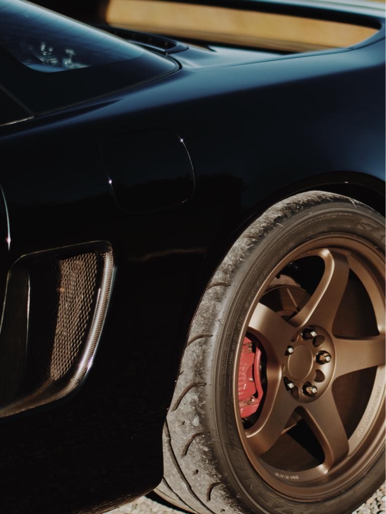
Yeah the meaty fitment is one of my favorite visual things on the car right now, especially the rears. I almost had some stretch tho, as I originally ordered the 615ks, but they were out of stock. So I lucked out
Your AC post was a big help. I was on the fence if I should flush any parts, but you convinced me to do it.
Formula silver has been the favorite. Every day I change my mind and I’m convinced I’m going with a different color. Before doing the photoshop thing, I was thinking either white or mag blue. Now 2 more colors have entered the conversation: formula silver or titanium gunmetal. I have, uh, another set of wheels with a smaller range of colors I want to do, so what I do there will impact what I do with the LMGT4s.
Some small progress. I replaced the rear inner toe links with Cedar Ridge toe links last weekend. I've had these pieces for a while. When I first bought the car, I read a couple posts / articles about the NSX suffering from snap oversteer at the limit. This freaked me out. It seemed like one of the biggest improvements would come from replacing the inner toe links. The story goes that the rubber bushings deflect and change the toe under hard cornering, making the car feel unpredictable. At worst this causes toe out, then sudden oversteer. Maybe this is the reason factory alignments specify so much rear toe in? Anyway, heim joints for the win.
This was supposed to be the side project while I was replacing the wheel bearings / hubs. I wasn't able to break the axle nuts loose, so the toe links became the main event.
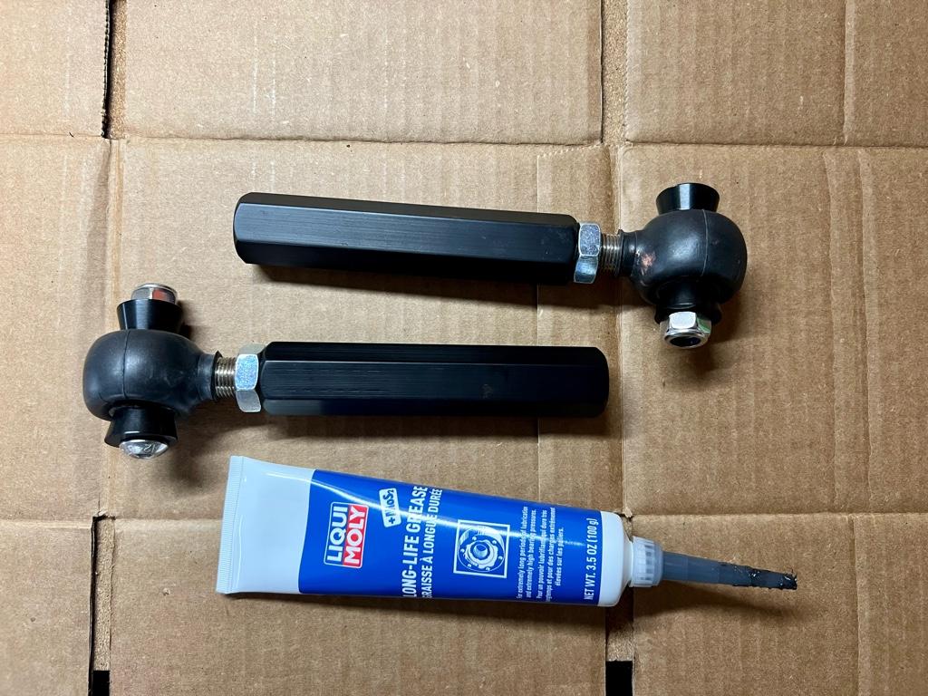
A while back I screwed everything together and put the rubber boots on. Dave from CRF told me I should use moly grease in the boots, so that's what I did.
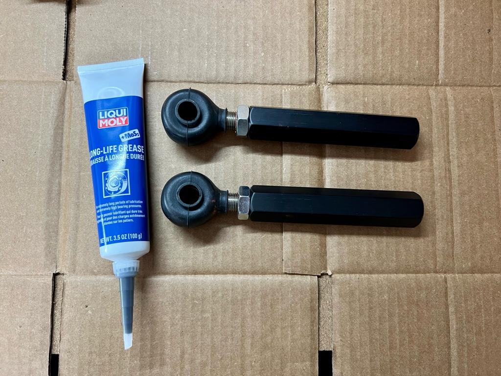
Then here they are packed with grease and the standoffs installed. The bolt through them is to make sure the standoffs don't pop off:
I'll get a real alignment soon, but I wanted the car to be drivable in the meantime. The goal was to initially end up with the same toe post-toe-link-install. Before tearing anything apart I measured the current toe. I got these Tenhulzen alignment plates and set them up:
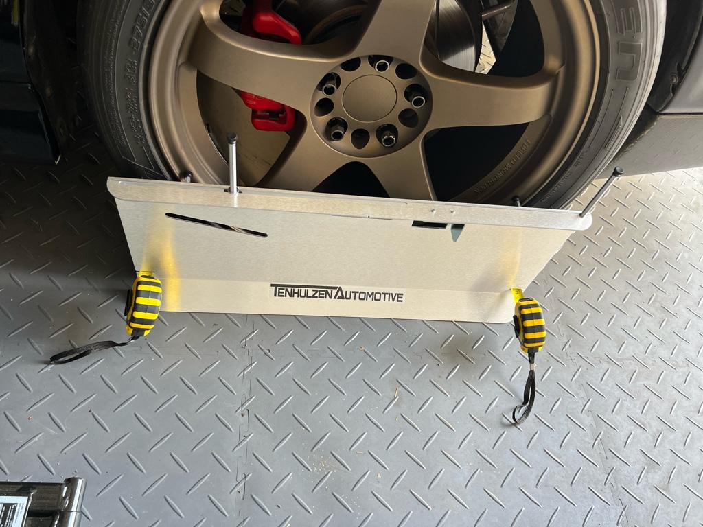
The rear had 3/16" (4.7mm) of total toe in. Seems like a lot to me, but it's close to factory spec.
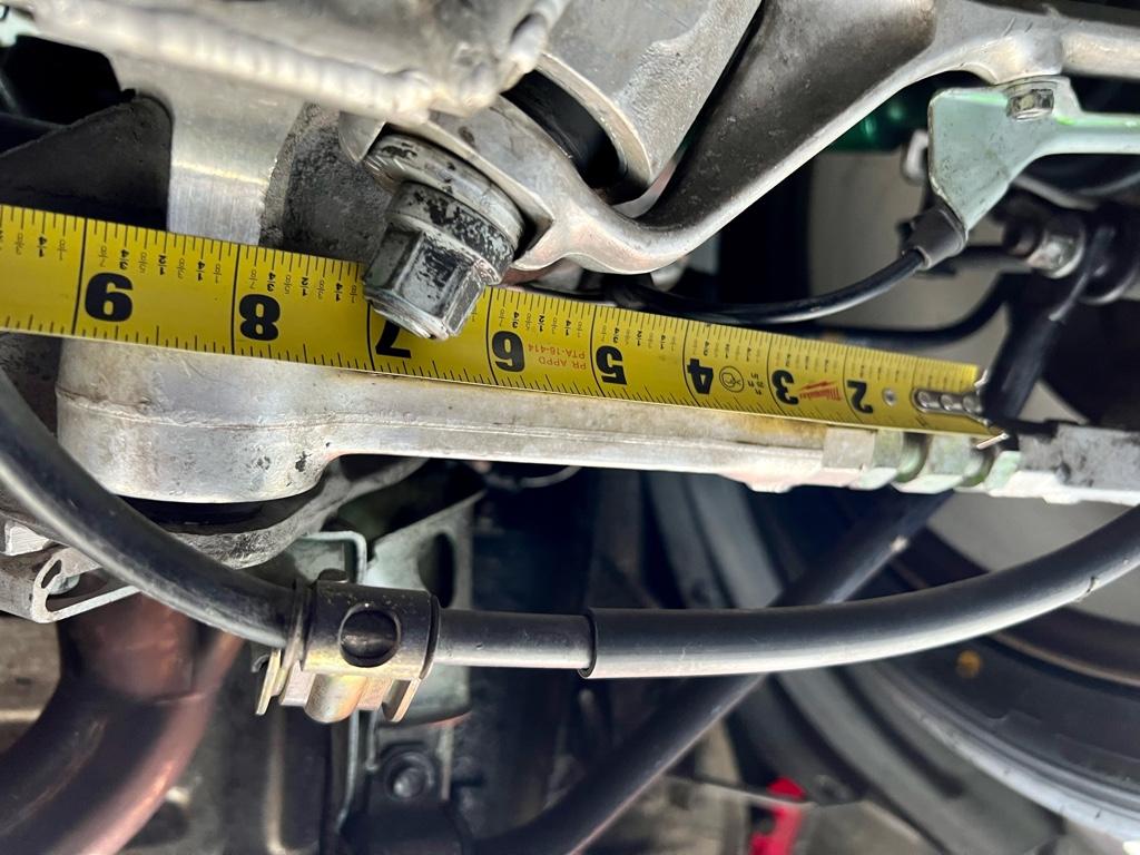
In an effort to get it back together correctly, and get both sides even (no dog tracking!), I tried to find a clear spot I could measure before and after on each side. This measurement fit the bill: end of tape on the turnbuckle, then measure to the edge of the machined strip on the rear beam. That machined strip has a nice hard edge so I could get a good measurement. I measured it like 5 times on each side to make sure the measurement was repeatable. Both sides were surprisingly similar: 7 7/8".
The old links came out easy, yay. Next up, I wanted to make the new links as close in length to the old as I could. Here they are next to one of the old links:
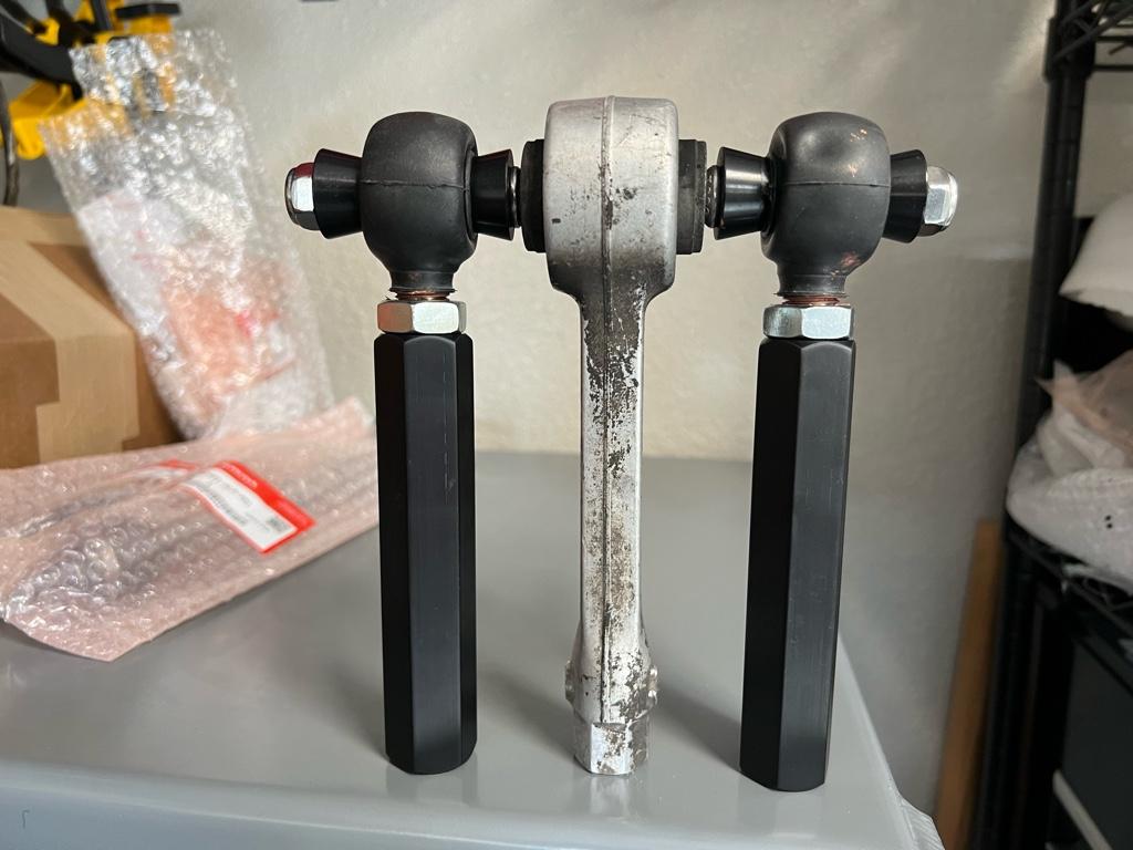
One thing I wasn't sure of until I got the old links out was the thread direction of the turnbuckle into the inner link. They are left hand threads on both sides. This is cool cause you can spin the new link's aluminum block to adjust toe without breaking the outer link's jam nut.
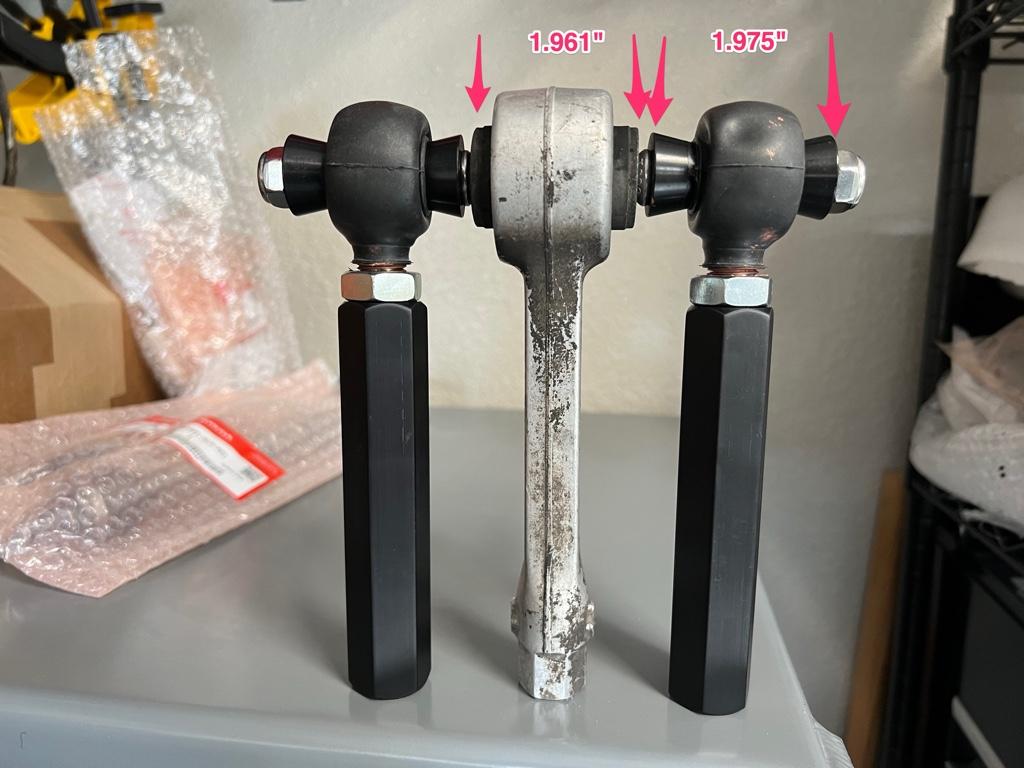
Up til this point things were, of course, going a little too easy. Welllll, turns out the new links didn't actually fit in the rear beam. OEM links were 1.961", the new links were 1.975". Too wide by 0.014". Seems like a pretty small number, but it was enough to make them not fit.
I spent a lot of time trying to figure out what to do and trying different orientations. Am I trying to install them at the wrong angle? Do they need to come in through the side? Can I spread the mounting points a tiny bit (no)?
I wasn't sure if the shoulders on the standoffs were fully seating in the heims. Maybe the layer of grease was the difference? Or maybe the boots were getting in the way? I pulled off one of the boots and measured everything to see where the extra material was.
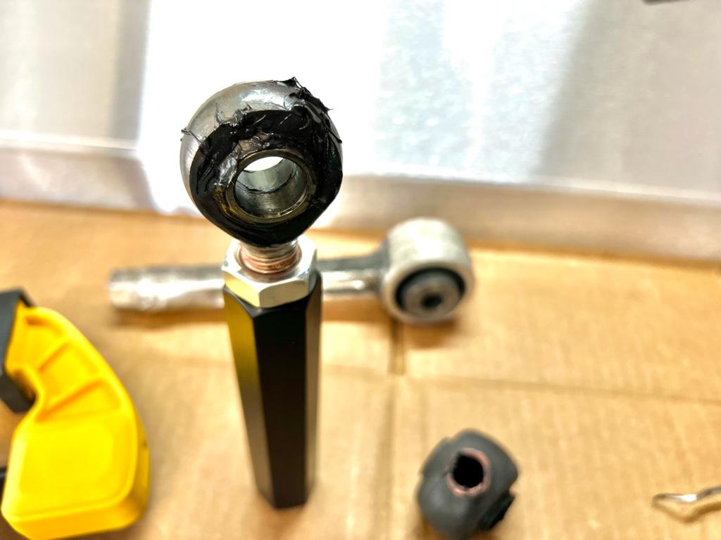
The standoffs were, in fact, fully seating. Maybe the heims included in my kit were a little wider than usual? Ultimately I decided to file down each of the standoffs. I put the file on the bench and pushed the standoffs over the file to keep the faces flat.
After tons of filing and checking, I got one down to 1.967" total, figured maybe that was enough and did a test fit. It was enough to fit very snugly in the rear beam. I made the other one the same and got them both bolted up.
After things were all settled and adjusted to be exactly the initial measurements from the turnbuckle to the rear beam, I pulled a little toe out of the rear to end up with a total of 1/8" (3.1mm).
I measured the front toe with the alignment plates and there was 1/8" toe-in. Unusual considering all the NSX specs I've found have a little front toe out. After a bunch of reading about other folks' NSX setups, I want to try 3mm rear and 2mm front toe out out of curiosity. Going from F:+3.1mm, R:+4.7mm to F:-2mm, R:+3mm should be a big change / improvement on turn in. This is not dissimilar from the setup I ran on my old EF (though slightly less rear toe in)....
I'll be replacing the front tie rods from the rack to the knuckle soon, and I'll shoot for the 2mm toe out just to see what it feels like before taking the car in for a real alignment.
This was supposed to be the side project while I was replacing the wheel bearings / hubs. I wasn't able to break the axle nuts loose, so the toe links became the main event.
A while back I screwed everything together and put the rubber boots on. Dave from CRF told me I should use moly grease in the boots, so that's what I did.
Then here they are packed with grease and the standoffs installed. The bolt through them is to make sure the standoffs don't pop off:
I'll get a real alignment soon, but I wanted the car to be drivable in the meantime. The goal was to initially end up with the same toe post-toe-link-install. Before tearing anything apart I measured the current toe. I got these Tenhulzen alignment plates and set them up:
The rear had 3/16" (4.7mm) of total toe in. Seems like a lot to me, but it's close to factory spec.
In an effort to get it back together correctly, and get both sides even (no dog tracking!), I tried to find a clear spot I could measure before and after on each side. This measurement fit the bill: end of tape on the turnbuckle, then measure to the edge of the machined strip on the rear beam. That machined strip has a nice hard edge so I could get a good measurement. I measured it like 5 times on each side to make sure the measurement was repeatable. Both sides were surprisingly similar: 7 7/8".
The old links came out easy, yay. Next up, I wanted to make the new links as close in length to the old as I could. Here they are next to one of the old links:
One thing I wasn't sure of until I got the old links out was the thread direction of the turnbuckle into the inner link. They are left hand threads on both sides. This is cool cause you can spin the new link's aluminum block to adjust toe without breaking the outer link's jam nut.
Up til this point things were, of course, going a little too easy. Welllll, turns out the new links didn't actually fit in the rear beam. OEM links were 1.961", the new links were 1.975". Too wide by 0.014". Seems like a pretty small number, but it was enough to make them not fit.
I spent a lot of time trying to figure out what to do and trying different orientations. Am I trying to install them at the wrong angle? Do they need to come in through the side? Can I spread the mounting points a tiny bit (no)?
I wasn't sure if the shoulders on the standoffs were fully seating in the heims. Maybe the layer of grease was the difference? Or maybe the boots were getting in the way? I pulled off one of the boots and measured everything to see where the extra material was.
The standoffs were, in fact, fully seating. Maybe the heims included in my kit were a little wider than usual? Ultimately I decided to file down each of the standoffs. I put the file on the bench and pushed the standoffs over the file to keep the faces flat.
After tons of filing and checking, I got one down to 1.967" total, figured maybe that was enough and did a test fit. It was enough to fit very snugly in the rear beam. I made the other one the same and got them both bolted up.
After things were all settled and adjusted to be exactly the initial measurements from the turnbuckle to the rear beam, I pulled a little toe out of the rear to end up with a total of 1/8" (3.1mm).
I measured the front toe with the alignment plates and there was 1/8" toe-in. Unusual considering all the NSX specs I've found have a little front toe out. After a bunch of reading about other folks' NSX setups, I want to try 3mm rear and 2mm front toe out out of curiosity. Going from F:+3.1mm, R:+4.7mm to F:-2mm, R:+3mm should be a big change / improvement on turn in. This is not dissimilar from the setup I ran on my old EF (though slightly less rear toe in)....
I'll be replacing the front tie rods from the rack to the knuckle soon, and I'll shoot for the 2mm toe out just to see what it feels like before taking the car in for a real alignment.
Last edited:
I went from slight toe in, to zero toe, to the max recommended toe out and the difference in turn-in feel is very noticeable, you're going to love it.
Good to know! I’m looking forward to it for sure. I haven’t driven the car since the toe link change cause I’m doing other work. The next time I drive it will likely be with new setting both front and rear. Fully expecting a big behavior change!
The latest project was replacing the front tie-rods + added a knock bushing to the steering rack. My original plan was to do this work when I replaced the steering rack with a new rack I bought a little while back.
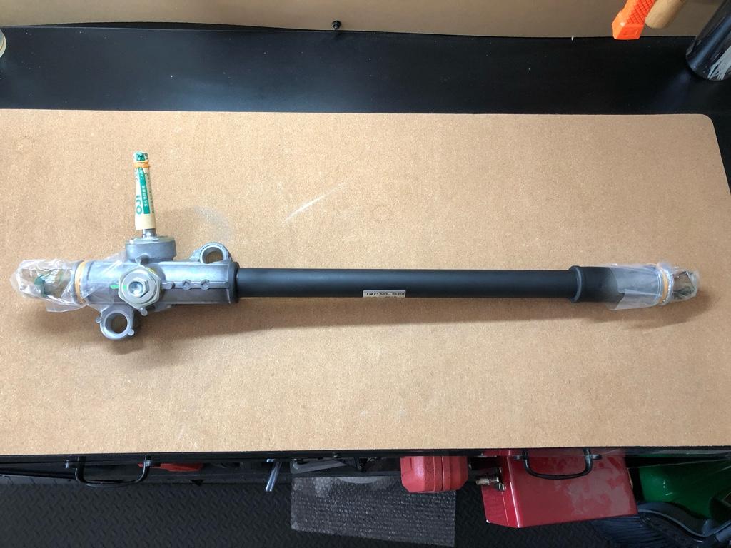
Installing the new rack is dependent on the Quaife short rack kit, though, which won't be finished until June or July at the earliest.
I ended doing this work now for 2 reasons:
1) The rear toe links necessitate an alignment anyway, might as well do that with new tie-rods up front, eh?
2) The car has the normal rack knock plus a steering wheel shake at 60-70mph. @Chris_Lum on instagram said he was able to solve his steering wheel shake with a knock bushing. I thought I'd give it a try.
He also said the knock bushing increased the steering effort by ~15% or 20%. I was curious what that felt like. The Quaife short rack will properly increase the effort by 20%, so maybe this'd be a good test. Would the bushing wear in? Any other adverse side effects? I'm planning on putting a knock bushing on the new rack to slow the wear, all around trying he bushing in the old rack felt like a good test.
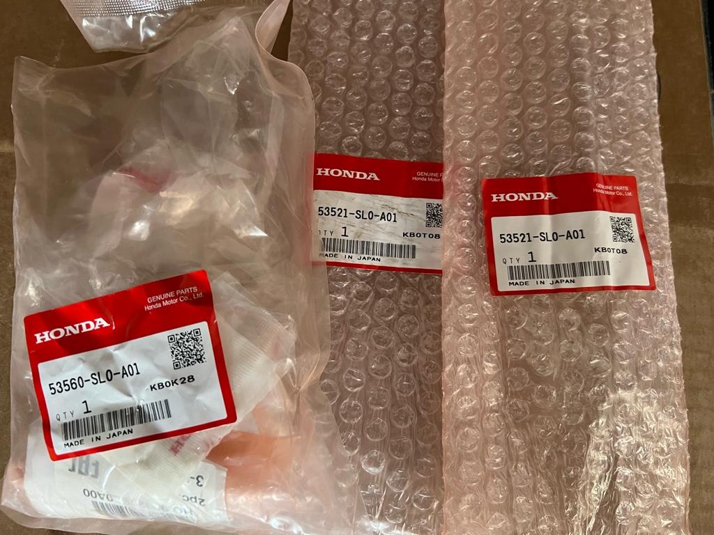
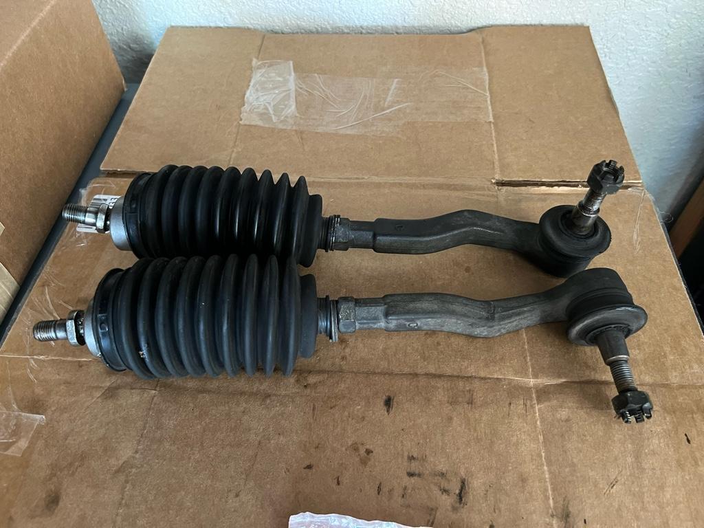
I replaced everything tie-rod-related from the rack to the knuckle: inner tie-rods, outers, boots, washers, etc. I thought I took a pic of the new parts before putting them on the car, but I guess I spaced. Here are the empty bags, tho!
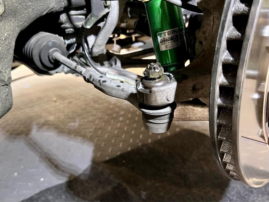
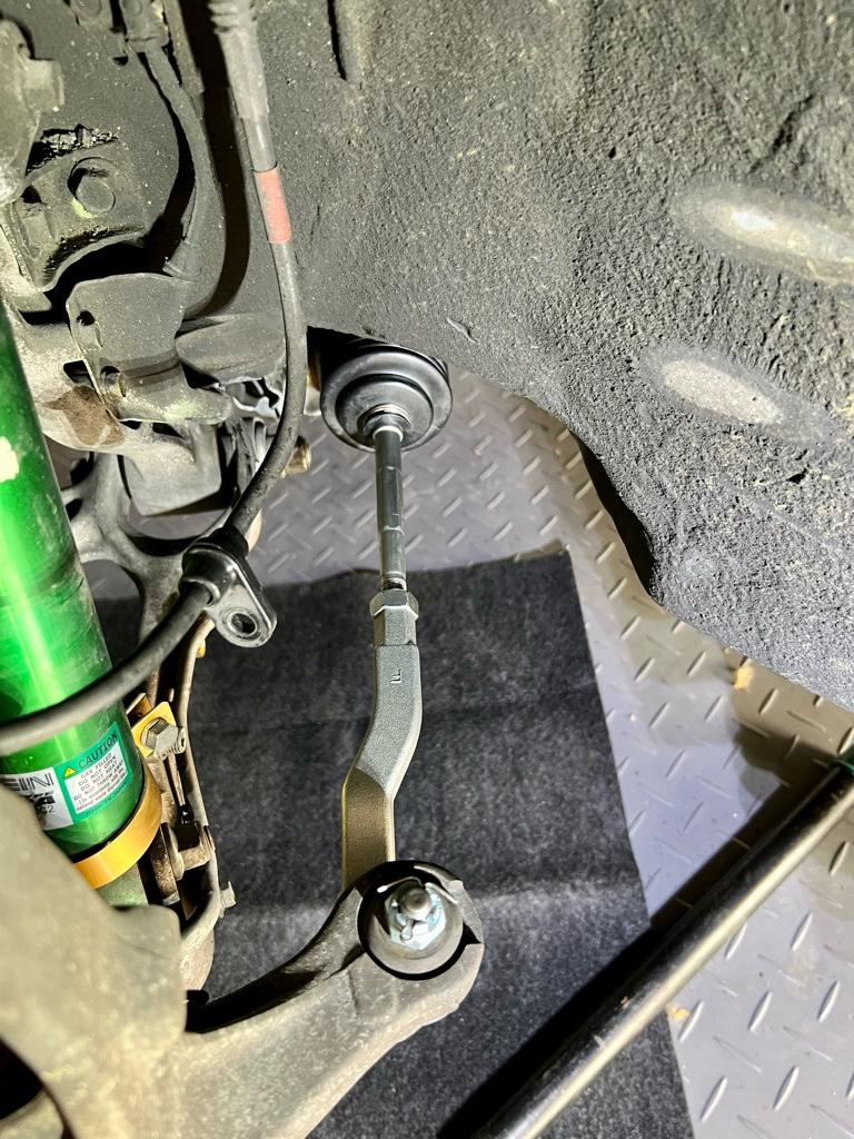
Begin! This project was pretty gooey, I took a lot fewer pics that I would have liked. First step, break the tie-rod ball joints loose. Before:
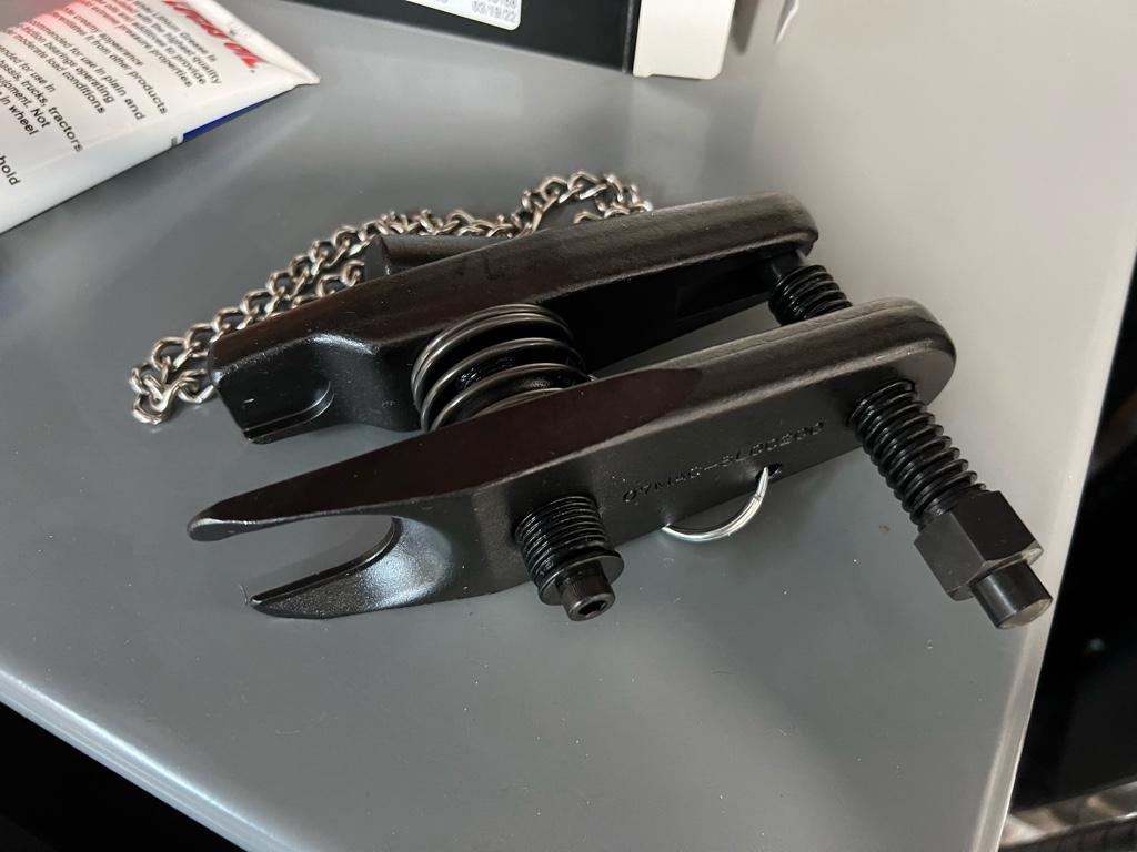
In my past car life, I'd always use one of those ball joint forks. You know, jam it between the joint and the suspension piece, then smack it with a hammer. It sucked every time, and I'd always tear the boot. Never again, I got the proper ball joint tool. Feels good man.
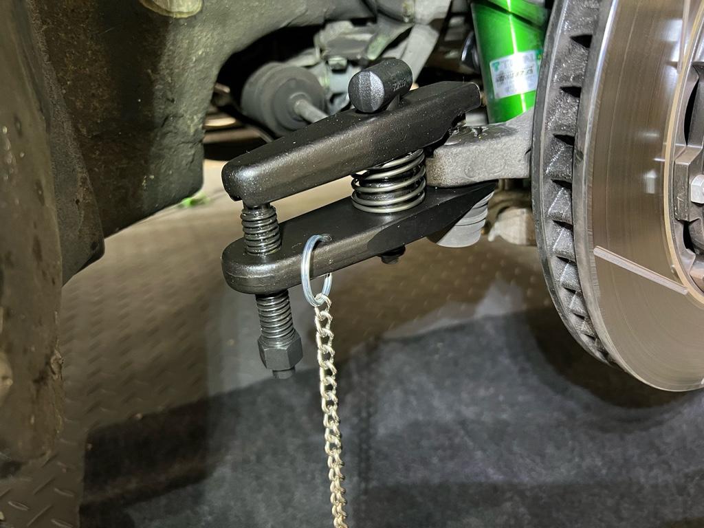
Then in use. Took like 30 seconds and no damage!
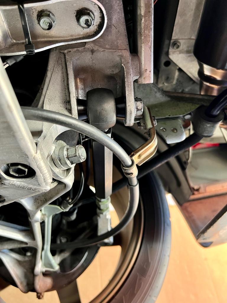
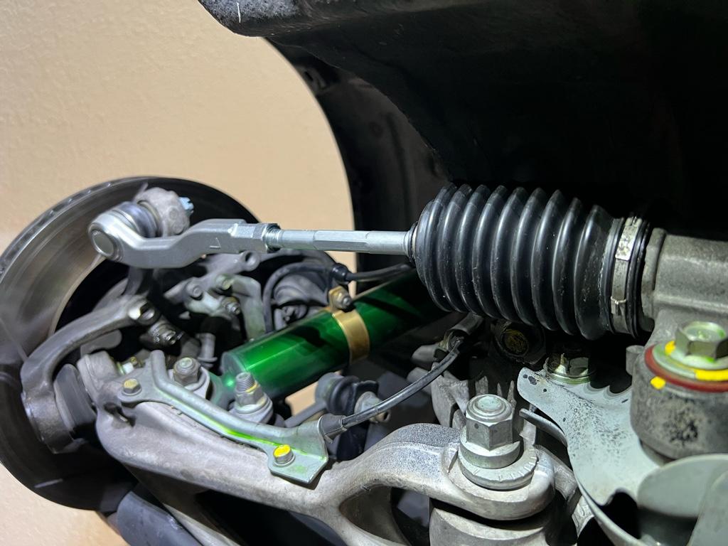
Sweet. Peel off the straps on the boots to reveal the inner tie rod and end of the rack. This is the passenger side:
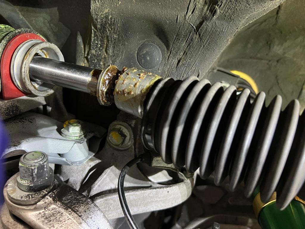
The next step was the hardest part of the whole job. Among the goo in the last pic, there is a washer folded over the inner tie-rod's mounting location. You need to unfold it in order to get a 17mm end wrench on there. The washer was much thicker than I expected and it was a total pain to unfold. Also it's folded over in 2 spots, one of them basically up against the body. After much contorting with a fat+sharp flathead screwdriver, I got them unfolded.
I broke the inner tie-rods loose with a full size 17mm end wrench, then unscrewed them with a shorty. Note that on each side all of this was a lot easier at full lock so the rack was out as far as possible.
Out! They seemed to be in reasonable shape, but I want that new car feel.
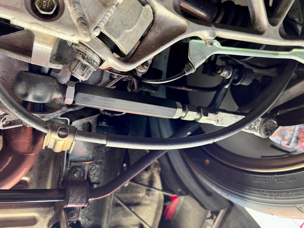
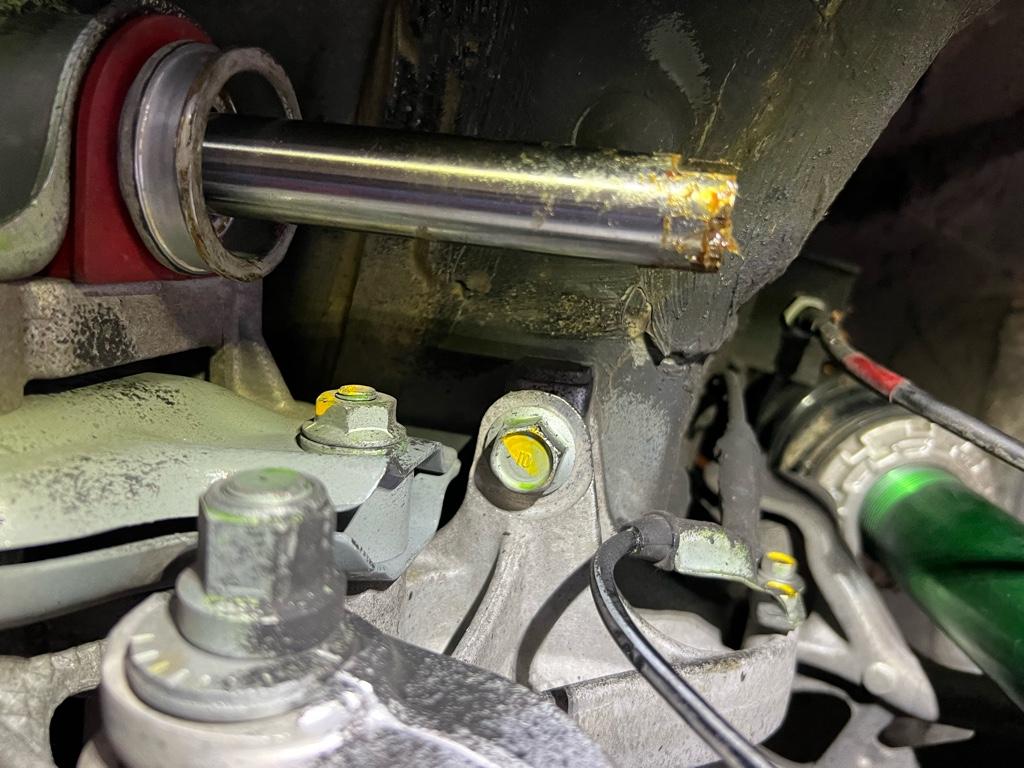
And the rack looks like this. This is again the passenger / problematic side of the rack:
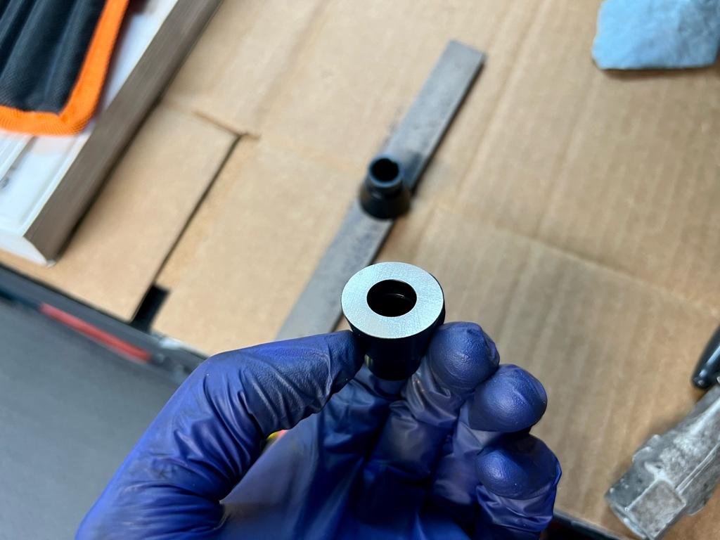
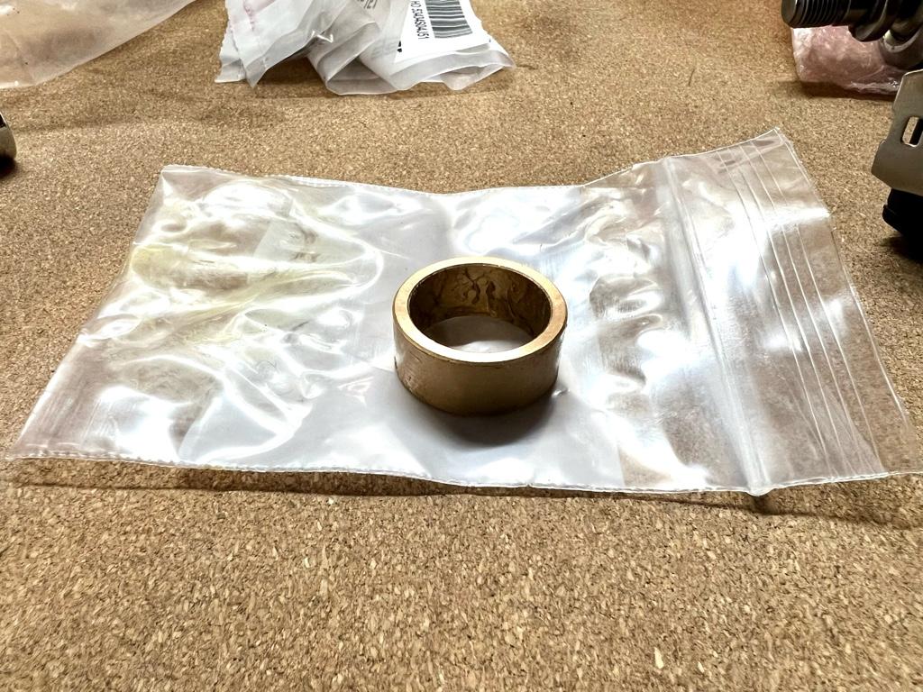
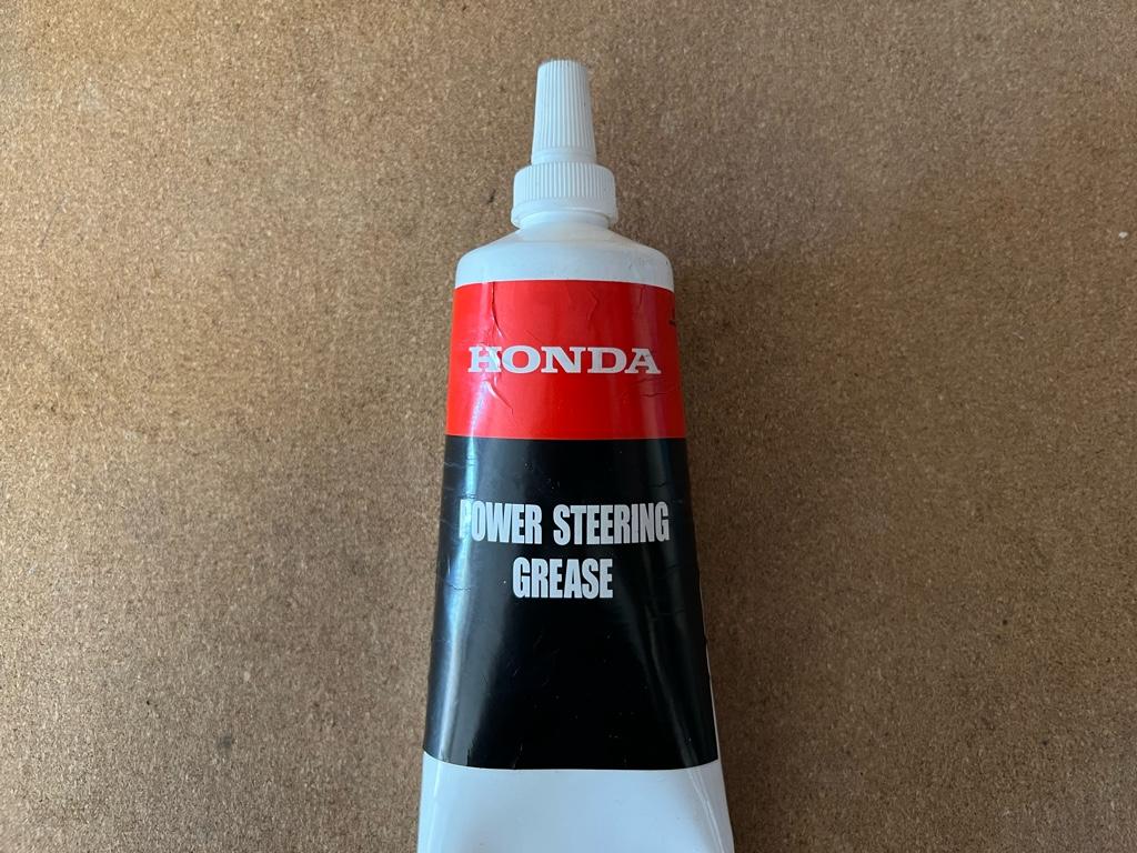
The knock bush. This one is from joe@cycleterminal. His are a lot cheaper ($55) than the Australian dude's bushing. I'll be getting another one for the new rack. It comes lubed up with Honda steering rack grease.
Then installed. I had to massage down a high spot with a tiny file on the end of the rack to get the bushing to nicely slide over. The high spot was right in the corner of where the end of the rack was cut down for the wrench. I've seen a couple videos of these where people just force them over a high spot and it stresses me out. It's possible to score the bushing when it's going on, and at full lock when it hits that high spot again.
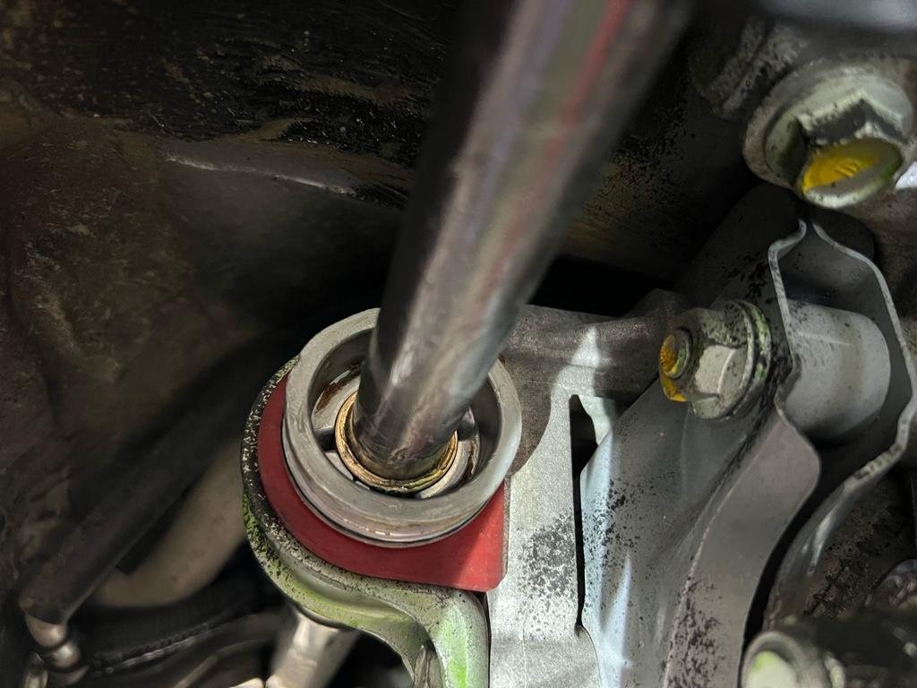
At this point I let the very small amount of loctite holding compound dry for probably 30 mins. Then the plan was to make sure it's well lubed and could run the whole range no issue. Seems like some people don't lube the bushing, it is oil-impregnated bronze after all, but after some reading these types of bushings are heavily lubed in industrial applications, especially when used in a linear slide (like a steering rack!). After more reading about grease types, it seemed like anything was fine. There were a few reports of Moly greases being not ideal as the solids can clog up in the bushing.
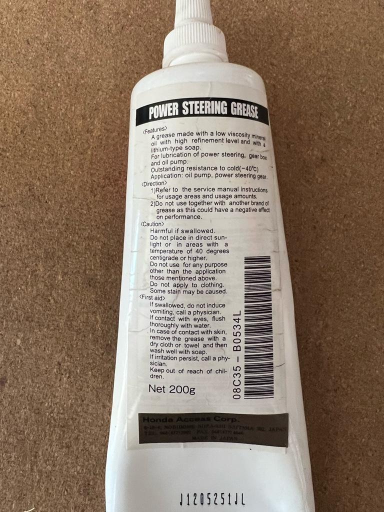
I settled on the Honda steering rack grease (old pn: 08733-B070E, new pn: 08C35-B0534L) as it's what was recommended for the inner joints and was probably already in there--the new rack's grease looks really similar. This stuff was kind of hard to find, and was unclear exactly what was in it. The label says "mineral oil with a lithium-type soap" if you were curious.
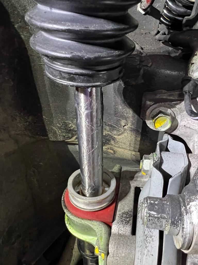
Ok lubed up. I did a couple passes of this: lube it, spin the steering wheel 360 from center each way a few times, full lock, wipe off the shaft, repeat. One final lube and it was ready for prime time.
Back together! Those dumb bent washers were a pain, but I got them bent.
Alignment
Next step was to sort of align it. The manual has you measure 11mm from the jam nut to the little step in the shaft. It's unclear exactly where on the step they want you to measure, so I picked the smaller edge. Here I am adjusting:
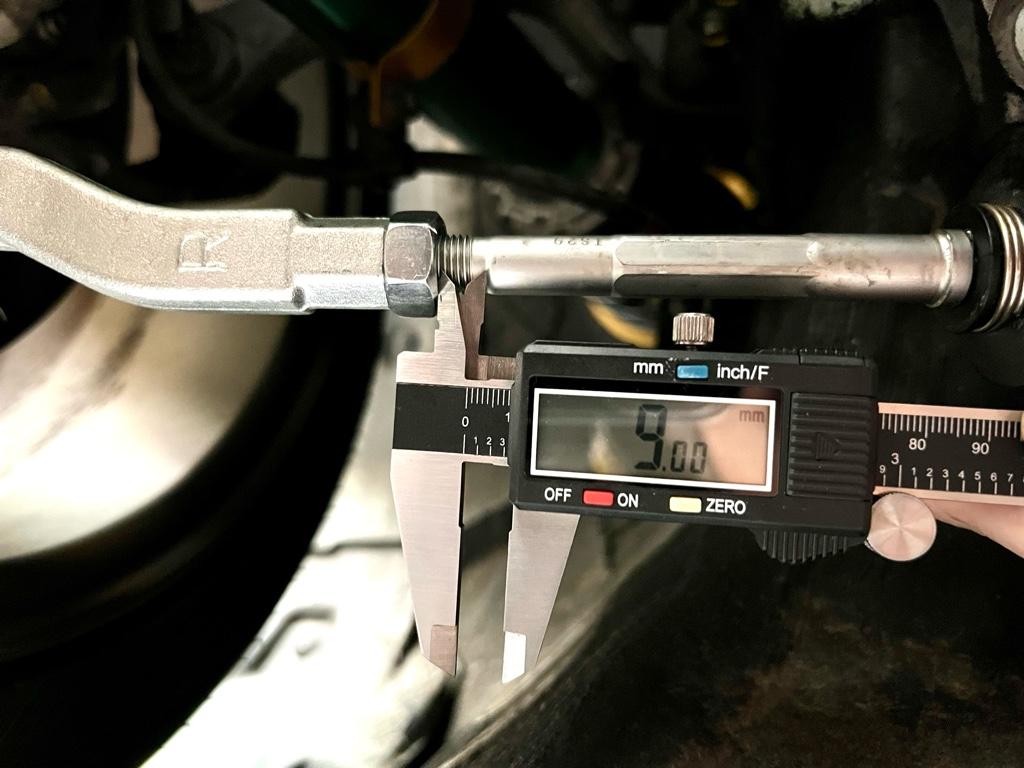
My old tie-rods were in totally different lengths left to right. I wanted the rack to be centered, so I started from scratch. Then the cycle was adjust, check on the toe plates, repeat. Here's a pic of the plates on the rears, but the front was the same vibe.

Adjusting the toe took me like 4 passes to get right: measure toe, nope, up in the air, adjust, measure, back down, roll the car, measure toe... Tiny adjustments make huge changes. After many adjustments, I calculated the rate to be about 3mm total change at the wheels for a 1mm total change at the tie-rods. I ended up with the nut-to-step measurements a hair over 10.5mm on each tie-rod for ~1/16" toe out.
I went for a short drive around the neighborhood and the steering wheel was waay off lol
I moved it over 2 splines (!!) and now it's proper centered.
Results
Sooo, is it better? OMG YES.
The first drive out with the new tie-rods was also the maiden voyage for a whole bunch of other changes: new rear toe links, less rear toe in, front toe out, aaand new front hubs, front wheel bearings, and studs.
The car feels great, a whole lot more solid and precise overall. The best part is...no more steering wheel shake! My old front wheel bearings and tie-rods weren't that bad, so I will attribute it mostly to the knock bushing.
Is there more effort in steering? Not for me. I had seen reports of the bushings 'breaking in' after a few hundred miles. In a few hundred miles, how much do you really exercise the rack? My goal in lubing and spinning the steering wheel with the car in the air was to simulate those couple hundred miles while keeping everything nice and juicy.
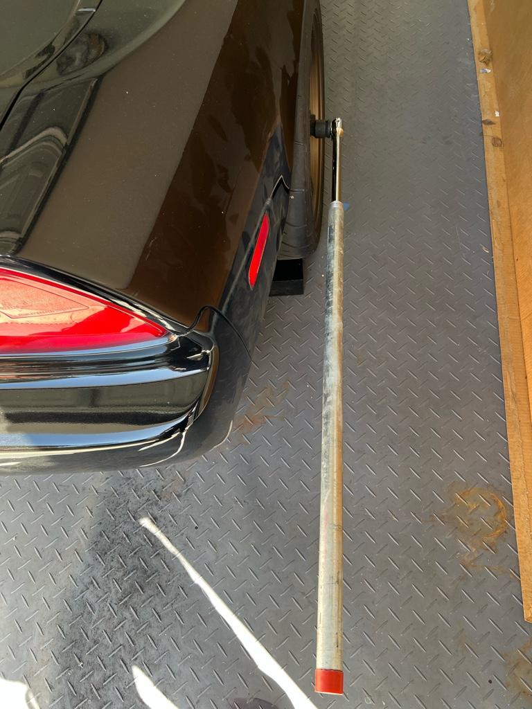
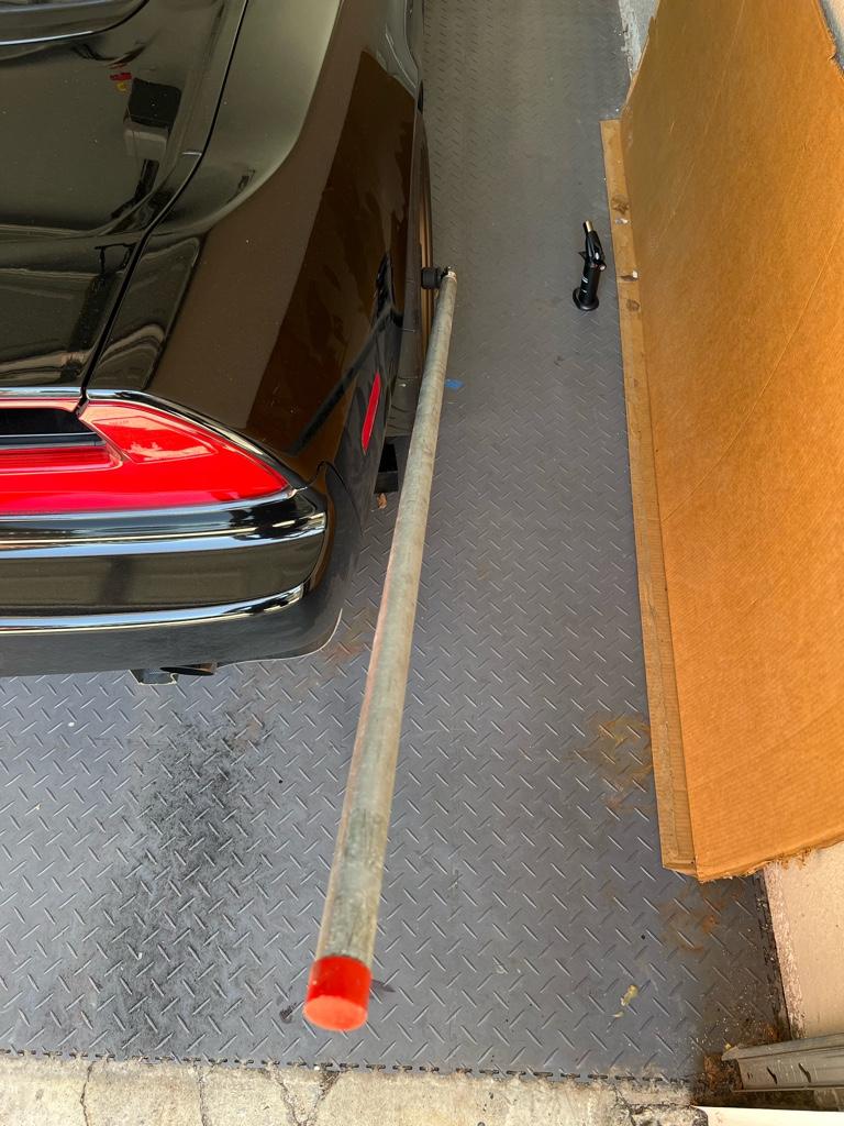
Wheel bearing posts coming soon. I still cant break the axle nuts on the rears, though, despite a growing collection of ever more comically large tools. So I may be taking it somewhere. I'll leave you with a pic of a 5 foot cheater on a 3/4 drive breaker bar. Even after basically jumping on this thing it wouldn't budge.
Installing the new rack is dependent on the Quaife short rack kit, though, which won't be finished until June or July at the earliest.
I ended doing this work now for 2 reasons:
1) The rear toe links necessitate an alignment anyway, might as well do that with new tie-rods up front, eh?
2) The car has the normal rack knock plus a steering wheel shake at 60-70mph. @Chris_Lum on instagram said he was able to solve his steering wheel shake with a knock bushing. I thought I'd give it a try.
He also said the knock bushing increased the steering effort by ~15% or 20%. I was curious what that felt like. The Quaife short rack will properly increase the effort by 20%, so maybe this'd be a good test. Would the bushing wear in? Any other adverse side effects? I'm planning on putting a knock bushing on the new rack to slow the wear, all around trying he bushing in the old rack felt like a good test.
I replaced everything tie-rod-related from the rack to the knuckle: inner tie-rods, outers, boots, washers, etc. I thought I took a pic of the new parts before putting them on the car, but I guess I spaced. Here are the empty bags, tho!
Begin! This project was pretty gooey, I took a lot fewer pics that I would have liked. First step, break the tie-rod ball joints loose. Before:
In my past car life, I'd always use one of those ball joint forks. You know, jam it between the joint and the suspension piece, then smack it with a hammer. It sucked every time, and I'd always tear the boot. Never again, I got the proper ball joint tool. Feels good man.
Then in use. Took like 30 seconds and no damage!
Sweet. Peel off the straps on the boots to reveal the inner tie rod and end of the rack. This is the passenger side:
The next step was the hardest part of the whole job. Among the goo in the last pic, there is a washer folded over the inner tie-rod's mounting location. You need to unfold it in order to get a 17mm end wrench on there. The washer was much thicker than I expected and it was a total pain to unfold. Also it's folded over in 2 spots, one of them basically up against the body. After much contorting with a fat+sharp flathead screwdriver, I got them unfolded.
I broke the inner tie-rods loose with a full size 17mm end wrench, then unscrewed them with a shorty. Note that on each side all of this was a lot easier at full lock so the rack was out as far as possible.
Out! They seemed to be in reasonable shape, but I want that new car feel.
And the rack looks like this. This is again the passenger / problematic side of the rack:
The knock bush. This one is from joe@cycleterminal. His are a lot cheaper ($55) than the Australian dude's bushing. I'll be getting another one for the new rack. It comes lubed up with Honda steering rack grease.
Then installed. I had to massage down a high spot with a tiny file on the end of the rack to get the bushing to nicely slide over. The high spot was right in the corner of where the end of the rack was cut down for the wrench. I've seen a couple videos of these where people just force them over a high spot and it stresses me out. It's possible to score the bushing when it's going on, and at full lock when it hits that high spot again.
At this point I let the very small amount of loctite holding compound dry for probably 30 mins. Then the plan was to make sure it's well lubed and could run the whole range no issue. Seems like some people don't lube the bushing, it is oil-impregnated bronze after all, but after some reading these types of bushings are heavily lubed in industrial applications, especially when used in a linear slide (like a steering rack!). After more reading about grease types, it seemed like anything was fine. There were a few reports of Moly greases being not ideal as the solids can clog up in the bushing.
I settled on the Honda steering rack grease (old pn: 08733-B070E, new pn: 08C35-B0534L) as it's what was recommended for the inner joints and was probably already in there--the new rack's grease looks really similar. This stuff was kind of hard to find, and was unclear exactly what was in it. The label says "mineral oil with a lithium-type soap" if you were curious.
Ok lubed up. I did a couple passes of this: lube it, spin the steering wheel 360 from center each way a few times, full lock, wipe off the shaft, repeat. One final lube and it was ready for prime time.
Back together! Those dumb bent washers were a pain, but I got them bent.
Alignment
Next step was to sort of align it. The manual has you measure 11mm from the jam nut to the little step in the shaft. It's unclear exactly where on the step they want you to measure, so I picked the smaller edge. Here I am adjusting:
My old tie-rods were in totally different lengths left to right. I wanted the rack to be centered, so I started from scratch. Then the cycle was adjust, check on the toe plates, repeat. Here's a pic of the plates on the rears, but the front was the same vibe.
Adjusting the toe took me like 4 passes to get right: measure toe, nope, up in the air, adjust, measure, back down, roll the car, measure toe... Tiny adjustments make huge changes. After many adjustments, I calculated the rate to be about 3mm total change at the wheels for a 1mm total change at the tie-rods. I ended up with the nut-to-step measurements a hair over 10.5mm on each tie-rod for ~1/16" toe out.
I went for a short drive around the neighborhood and the steering wheel was waay off lol
I moved it over 2 splines (!!) and now it's proper centered.
Results
Sooo, is it better? OMG YES.
The first drive out with the new tie-rods was also the maiden voyage for a whole bunch of other changes: new rear toe links, less rear toe in, front toe out, aaand new front hubs, front wheel bearings, and studs.
The car feels great, a whole lot more solid and precise overall. The best part is...no more steering wheel shake! My old front wheel bearings and tie-rods weren't that bad, so I will attribute it mostly to the knock bushing.
Is there more effort in steering? Not for me. I had seen reports of the bushings 'breaking in' after a few hundred miles. In a few hundred miles, how much do you really exercise the rack? My goal in lubing and spinning the steering wheel with the car in the air was to simulate those couple hundred miles while keeping everything nice and juicy.
Wheel bearing posts coming soon. I still cant break the axle nuts on the rears, though, despite a growing collection of ever more comically large tools. So I may be taking it somewhere. I'll leave you with a pic of a 5 foot cheater on a 3/4 drive breaker bar. Even after basically jumping on this thing it wouldn't budge.
Last edited:
- Joined
- 3 May 2020
- Messages
- 149
Hey glad you fixed your steering shake! I have about 200 miles on my knock bushing now and steering effort feels pretty much back to normal (or I just got used to it, or a bit of both). I'm glad more people are trying the knock bushing to solve high speed steering wheel shake. It still baffles me how this car is 30 years old and more people haven't recommended the knock bushing to fix that issue so far. Let's keep the word on that going!
Hey glad you fixed your steering shake! I have about 200 miles on my knock bushing now and steering effort feels pretty much back to normal (or I just got used to it, or a bit of both). I'm glad more people are trying the knock bushing to solve high speed steering wheel shake. It still baffles me how this car is 30 years old and more people haven't recommended the knock bushing to fix that issue so far. Let's keep the word on that going!
Thanks! It does feel good to have the issue solved.
I didn’t realize the steering wheel shake was common. When I first got the car it was _really_ bad. I replaced the loose 2pc rotors and it improved, then the knock bushing solved it.
I think for my stuck rear axle nuts, the solution was soaking in the 50/50 ATF & acetone mix, and you could torch the nut itself since you're planning on replacing the bearing anyways (with the ABS sensor off too..). The face of the nut has a lot of surface area to grip with especially if it's a bit rusted. I sat there with an impact going full blast for probably 10-15 seconds before the nut moved, it seems excessive but it needs a lot of, well, impact to break loose.
I think for my stuck rear axle nuts, the solution was soaking in the 50/50 ATF & acetone mix, and you could torch the nut itself since you're planning on replacing the bearing anyways (with the ABS sensor off too..). The face of the nut has a lot of surface area to grip with especially if it's a bit rusted. I sat there with an impact going full blast for probably 10-15 seconds before the nut moved, it seems excessive but it needs a lot of, well, impact to break loose.
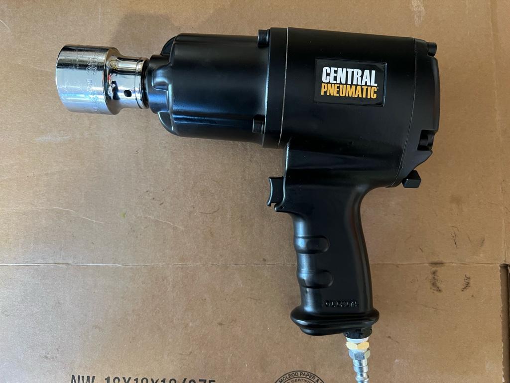
I just skipped the line and went right to the front door with this:
https://www.harborfreight.com/3-4-quarter-inch-heavy-duty-impact-wrench-66984.html
My kids call it the "big beast" and even choked on a skinny 1/4" air quick connect, this thing blasted off the axle nuts that were crusty and horrible on my AT. It turned what would have been days of struggle into a 10 second deal: Chugga-chugga- BAM! I didn't even have to bend out the punch dimple on the nut.
Ok noted, maybe I need a bigger impact gun. Someone also DMd me and showed me the Jack + breaker bar technique, but I don’t have a jack. So I guess I’m buying a Jack or a bigger gun. Probably the latter for space reasons.
Both of you, how big is your compressor tank? What pressure did you run? I have a little 6 gal pancake running 90-100lbs in the line and I figured it wouldn’t be enough. My 600ftlb gun did nothing, and the compressor kicks on after like 2 seconds of trying
Both of you, how big is your compressor tank? What pressure did you run? I have a little 6 gal pancake running 90-100lbs in the line and I figured it wouldn’t be enough. My 600ftlb gun did nothing, and the compressor kicks on after like 2 seconds of trying
Mine was an electric impact, that HF one Honcho linked should be good but I've used my Rigid 1/2" which barely works. I don't have any air tools, but the shop I have access to has a large 100-ish gallon tank @ 125 psig anyways.
Front Wheel bearings
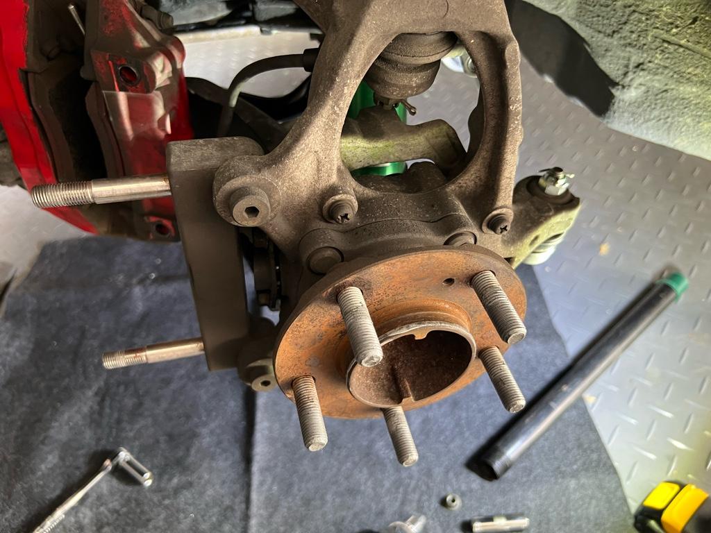
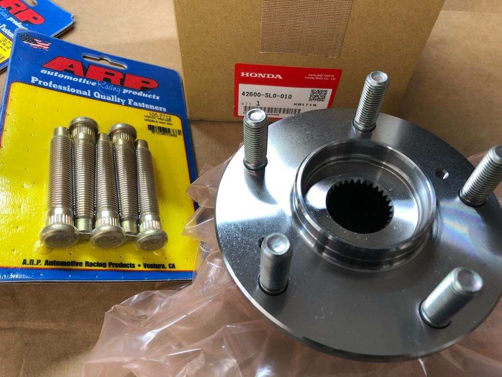
I finished replacing the front wheel bearings, hubs, and longer ARP studs a couple weeks ago. This all started because of the longer wheel studs. The studs on the car were in pretty rough shape, and it felt like there wasn't much thread engagement with the R40 lugnuts. I figured I could buy a set and quickly swap them out. Turns out nope, the studs were tacked into the hubs.
You can see the welds here, there were two little tack welds on each stud.
I could have used the old stuff, but I didn't want any downtime, and like most things, it escalated. This felt like a good opportunity for all new stuff. I bought new bearings from rock auto, then brand new hubs, ABS rings, etc from Amayama. I got the new bearings pretty quickly.
But then Amayama cancelled the front hubs and ABS rings from my order. Used hubs were fine, I just needed to find a used hub / bearing setup I could strip the hubs and ABS rings from. Ebay stuff was expensive and from sellers with spotty response rates. I posted a WTB thread and Christian from ATR responded. He told me he had a set of front hubs/bearings with low miles and the bearings in good shape. Also like 1/2 price from ebay stuff IIRC, cool.
I didn't take any before pics of the hubs/bearings, but they were pretty clean. I decided to use the bearings as is, I'll replace with the brand new bearings sometime in the future. First step was to get the studs out: die grinder to the bearing housing.
After the studs were out, I took a wire wheel to the hubs all over. I wanted to get any rust off and paint the center of the hub to prevent new rust.
Then I painted them with 3000deg high temp paint. Done!
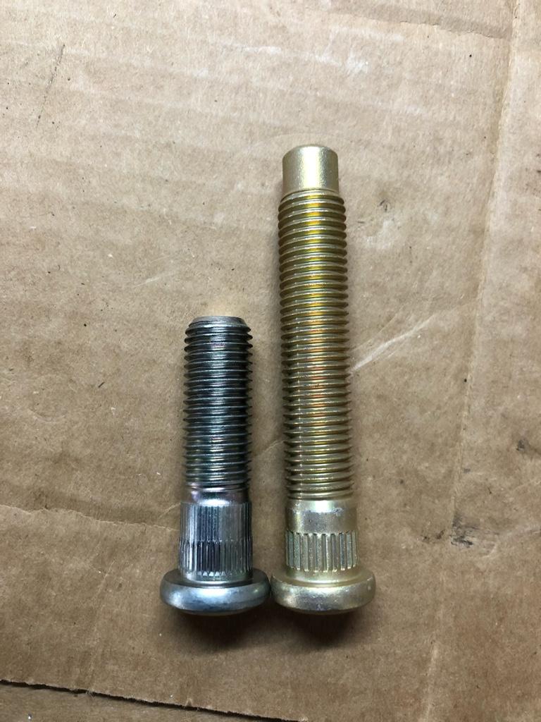
Studs up next. They are the long dong ARP studs PN. Here's the difference in length vs a new stock stud:

Ok, now to "press" the studs into the hub. I used a ratchet to get them started in the hub, then I used the impact gun to fully seat them. I don't love this method, but I got no press. I know ARP studs are pretty strong, but it feels not ideal to put tons of torque into them when they will live at 80 ftlbs in real life.
Install
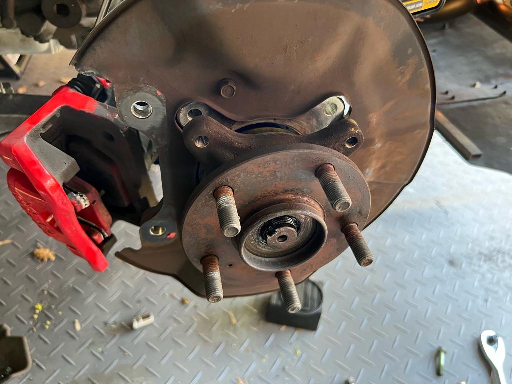
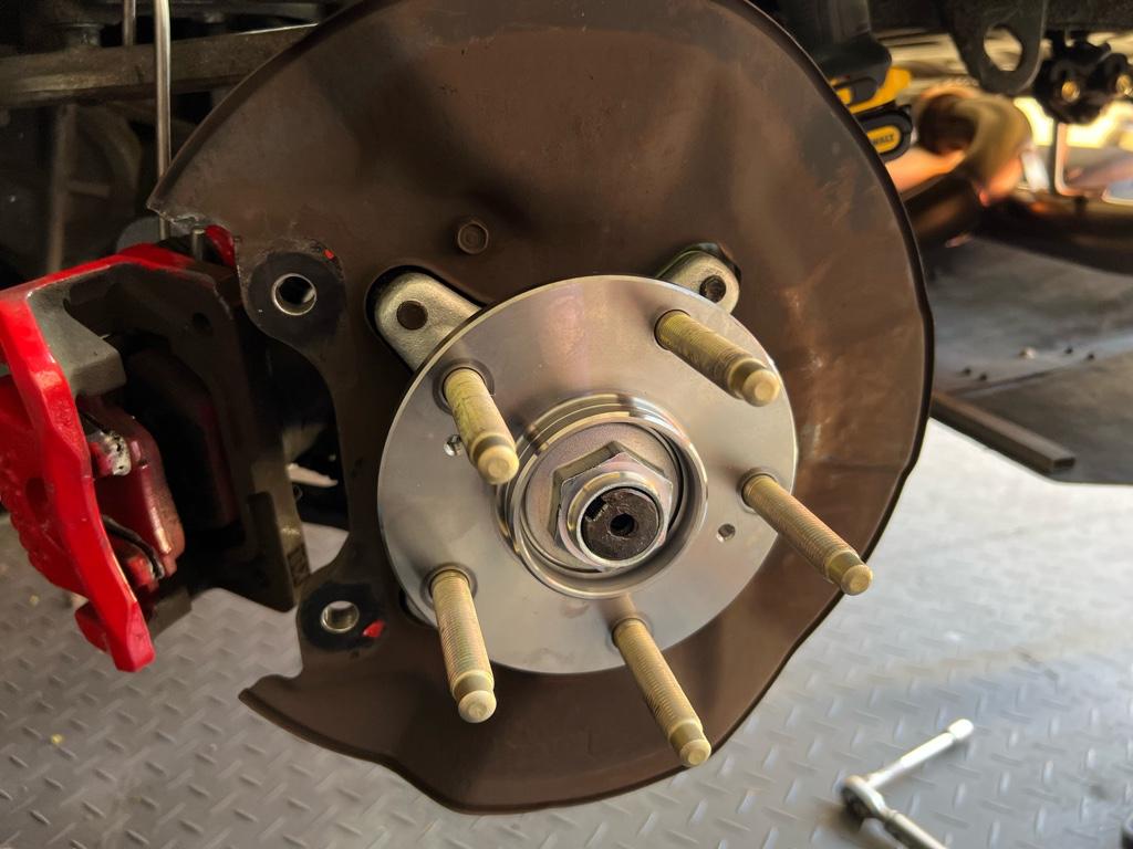
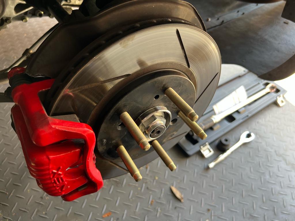
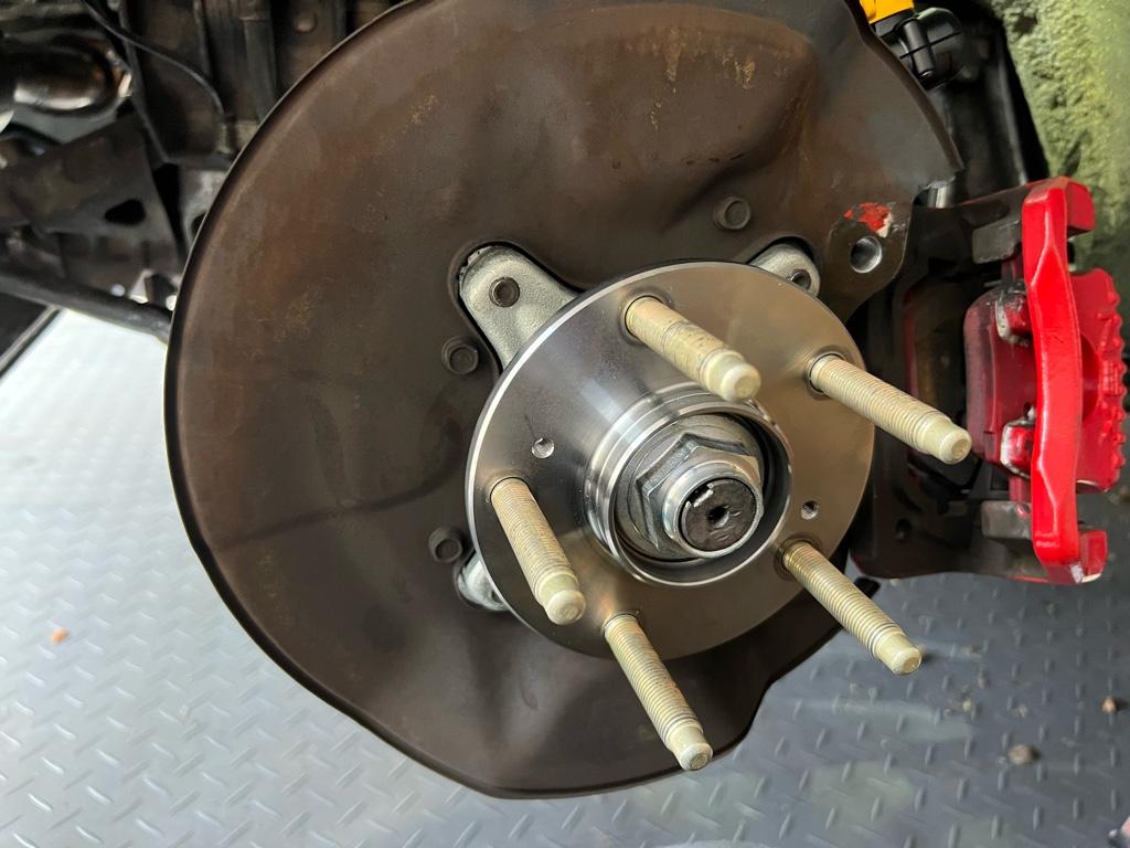
With everything all prepped, install was pretty easy. The old hubs, all rusty and gross:
Old hubs off:
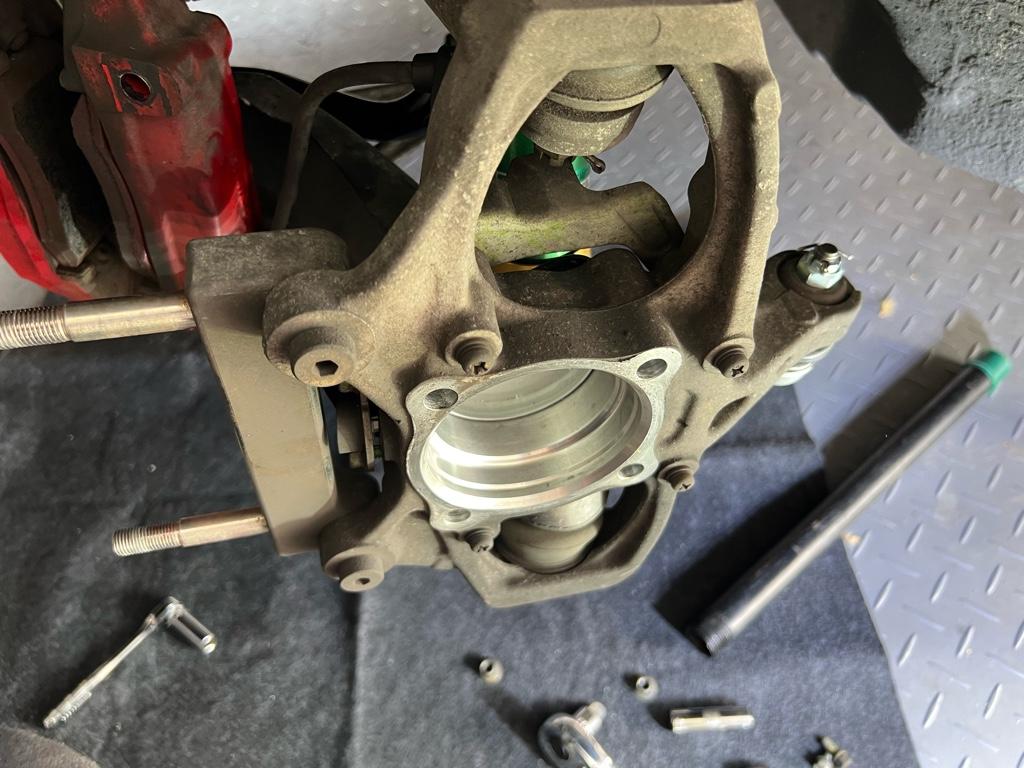
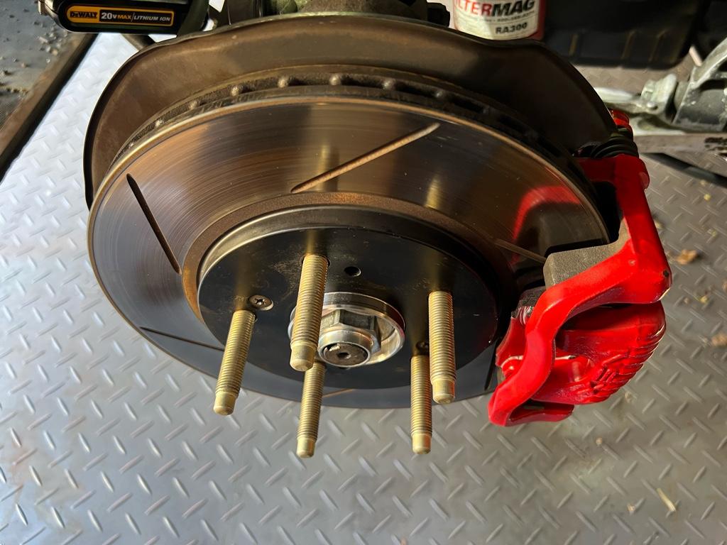
New hubs on:
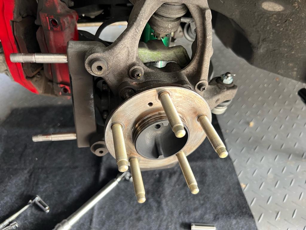
Then the brakes back together. It was tough to find the torque specs for the BBK’s caliper-to-bracket nuts, but I finally did. Brembo specifies 40 ftlb.
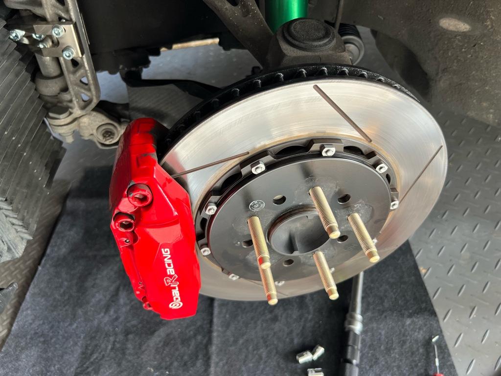
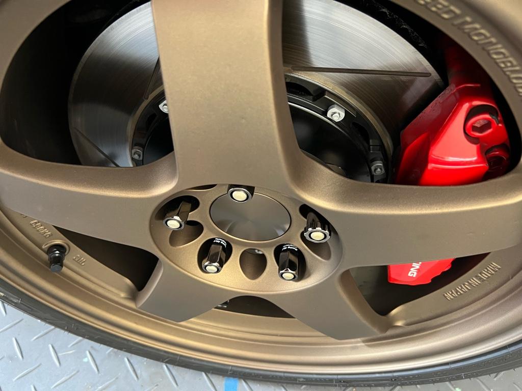
With the lugnuts on, here is the reveal. All the thread engagement!
This work was done alongside the front tie rod + knock bushing work, so I cant comment on the specific effects. But no steering wheel shake!
Next up is the rear wheel bearings. Bought a number of new tools and managed to break the drivers side loose + get everything replaced.
The passengers side is impossible, tho, despite many hours, 2 different big boy impact guns, a torch, omg 6 ft cheater, and cutting most of the nut. I can’t cut the nut flange without hurting the hub or axle, which presumably is where all the holding power is. I need a bigger air compressor? I have one more tool thing coming in the mail, but bundled with it are my low expectations. I have an appointment to take it to a shop this week. Super annoying as the actual wheel bearing replacement is so fast/easy.
I finished replacing the front wheel bearings, hubs, and longer ARP studs a couple weeks ago. This all started because of the longer wheel studs. The studs on the car were in pretty rough shape, and it felt like there wasn't much thread engagement with the R40 lugnuts. I figured I could buy a set and quickly swap them out. Turns out nope, the studs were tacked into the hubs.
You can see the welds here, there were two little tack welds on each stud.
I could have used the old stuff, but I didn't want any downtime, and like most things, it escalated. This felt like a good opportunity for all new stuff. I bought new bearings from rock auto, then brand new hubs, ABS rings, etc from Amayama. I got the new bearings pretty quickly.
But then Amayama cancelled the front hubs and ABS rings from my order
. Used hubs were fine, I just needed to find a used hub / bearing setup I could strip the hubs and ABS rings from. Ebay stuff was expensive and from sellers with spotty response rates. I posted a WTB thread and Christian from ATR responded. He told me he had a set of front hubs/bearings with low miles and the bearings in good shape. Also like 1/2 price from ebay stuff IIRC, cool.I didn't take any before pics of the hubs/bearings, but they were pretty clean. I decided to use the bearings as is, I'll replace with the brand new bearings sometime in the future. First step was to get the studs out: die grinder to the bearing housing.
After the studs were out, I took a wire wheel to the hubs all over. I wanted to get any rust off and paint the center of the hub to prevent new rust.
Then I painted them with 3000deg high temp paint. Done!
Studs up next. They are the long dong ARP studs PN. Here's the difference in length vs a new stock stud:
Ok, now to "press" the studs into the hub. I used a ratchet to get them started in the hub, then I used the impact gun to fully seat them. I don't love this method, but I got no press. I know ARP studs are pretty strong, but it feels not ideal to put tons of torque into them when they will live at 80 ftlbs in real life.
Install
With everything all prepped, install was pretty easy. The old hubs, all rusty and gross:
Old hubs off:
New hubs on:
Then the brakes back together. It was tough to find the torque specs for the BBK’s caliper-to-bracket nuts, but I finally did. Brembo specifies 40 ftlb.
With the lugnuts on, here is the reveal. All the thread engagement!
This work was done alongside the front tie rod + knock bushing work, so I cant comment on the specific effects. But no steering wheel shake!
Next up is the rear wheel bearings. Bought a number of new tools and managed to break the drivers side loose + get everything replaced.
The passengers side is impossible, tho, despite many hours, 2 different big boy impact guns, a torch, omg 6 ft cheater, and cutting most of the nut. I can’t cut the nut flange without hurting the hub or axle, which presumably is where all the holding power is. I need a bigger air compressor? I have one more tool thing coming in the mail, but bundled with it are my low expectations. I have an appointment to take it to a shop this week. Super annoying as the actual wheel bearing replacement is so fast/easy.
Rear wheel bearings
The rear wheel bearings were considerably more difficult than the front due to axle nut pain.
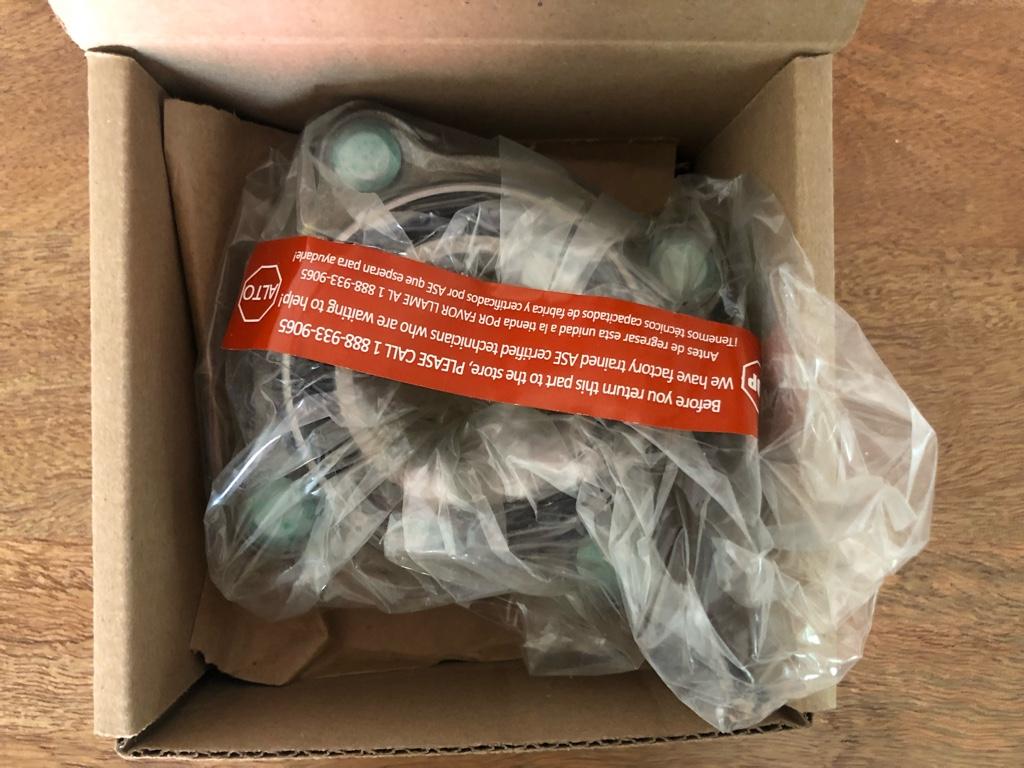
Unlike the fronts, I managed to get all new parts. For the bearings, I went with Beck & Arnley (PN 051-4070) as they use NTN bearings just like OEM. Amayama had the new rear hubs, which was fortunate, then the same ARP studs as the front.
I had to knock out the OE studs. A lugnut on the end of the lug, a couple of washers, and a hammer did the trick.
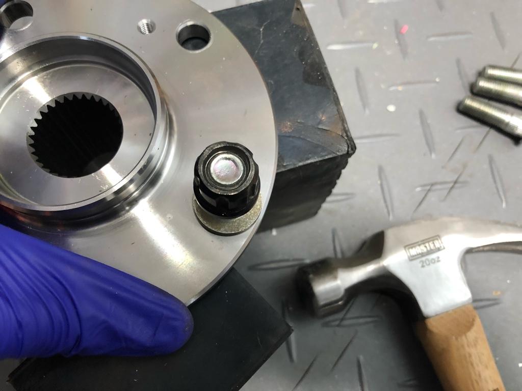
Then I started the ARP studs with the ratchet.
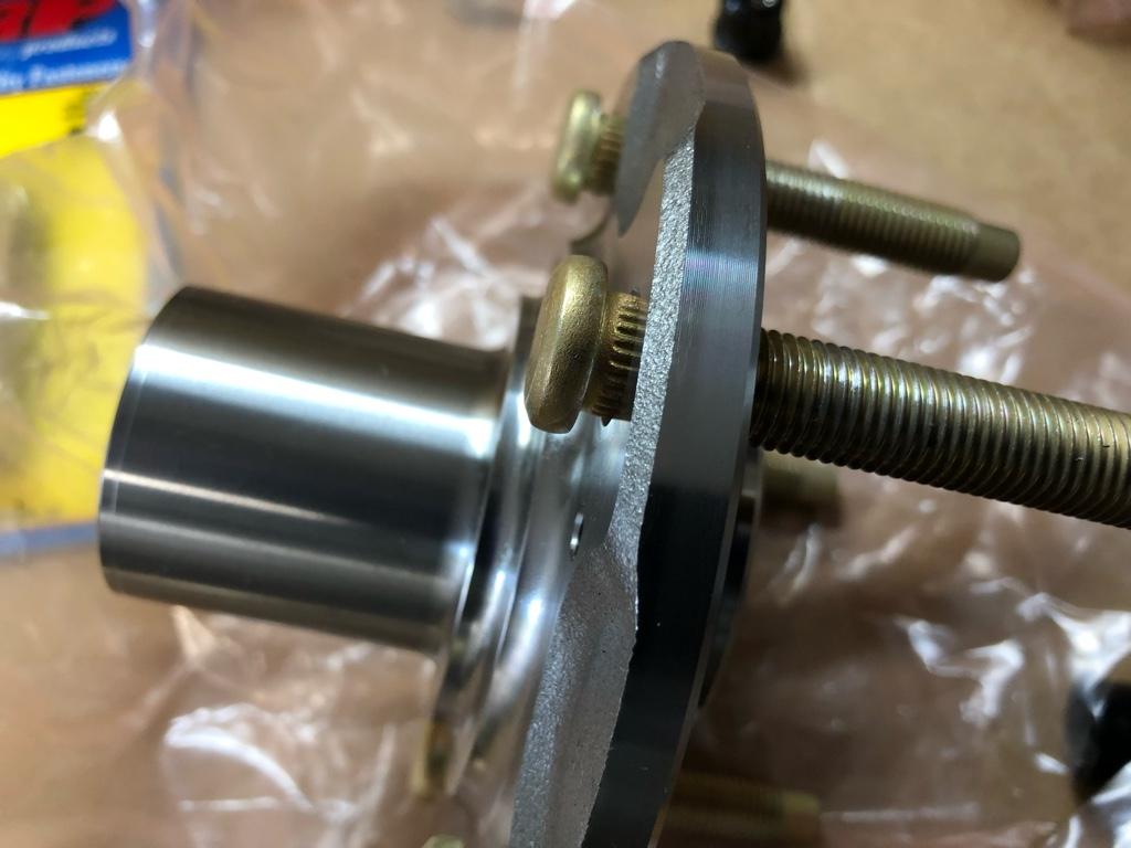
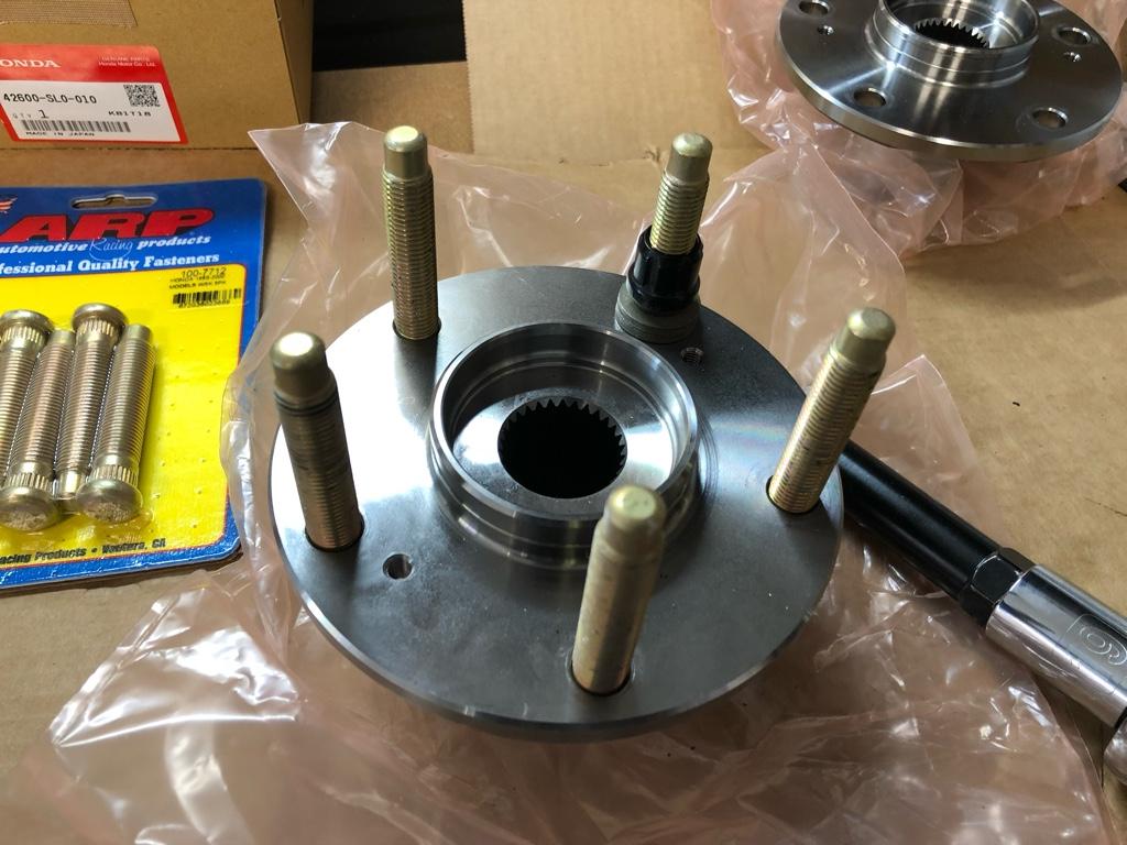
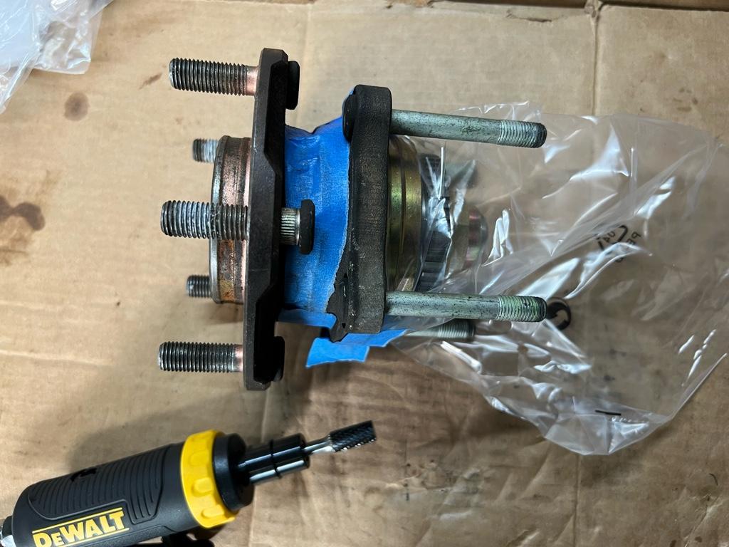
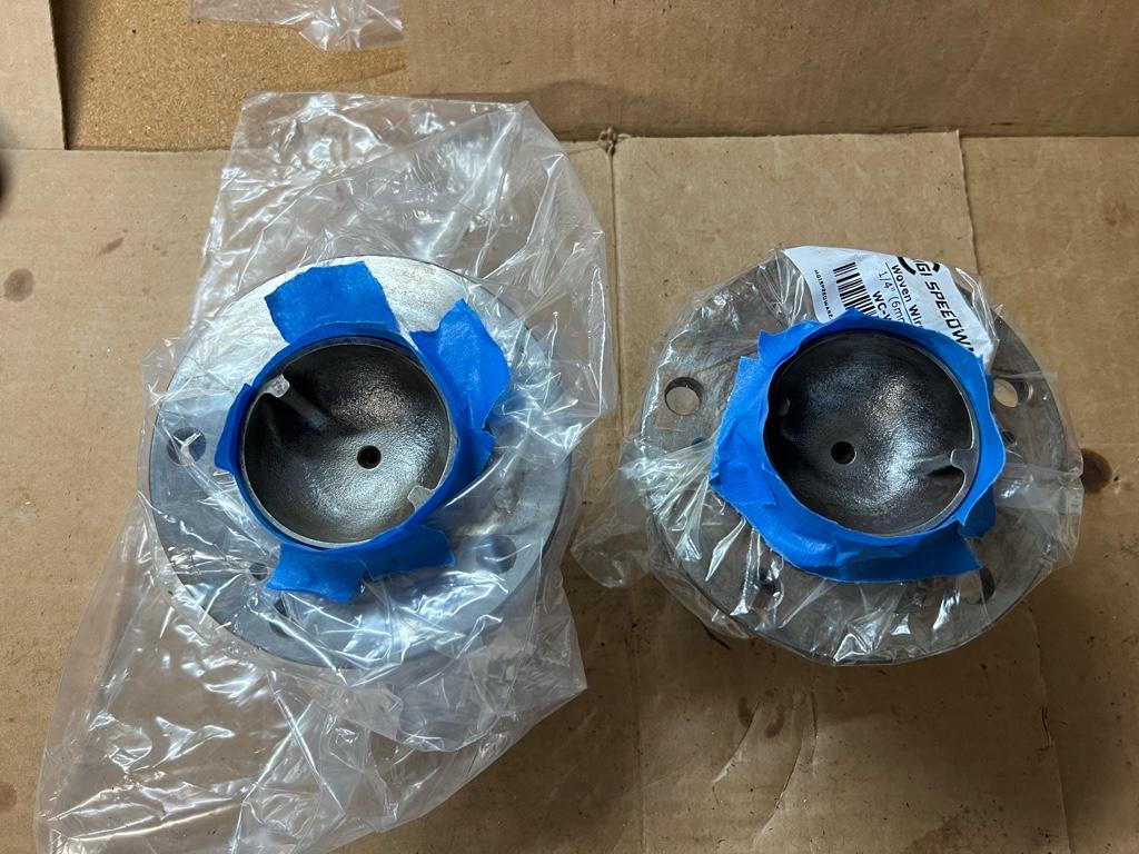
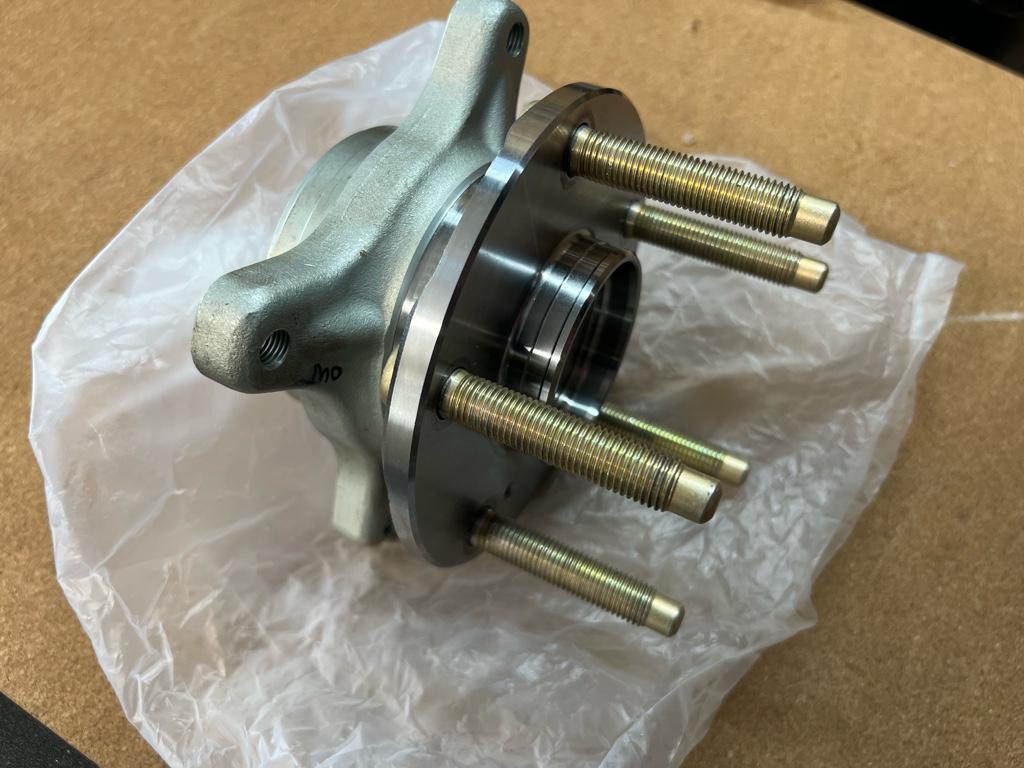
But I could only get them like 1/2 way by hand. I used the impact gun method just like with the fronts to seat them. Here's the hubs and bearings ready to be pressed together:
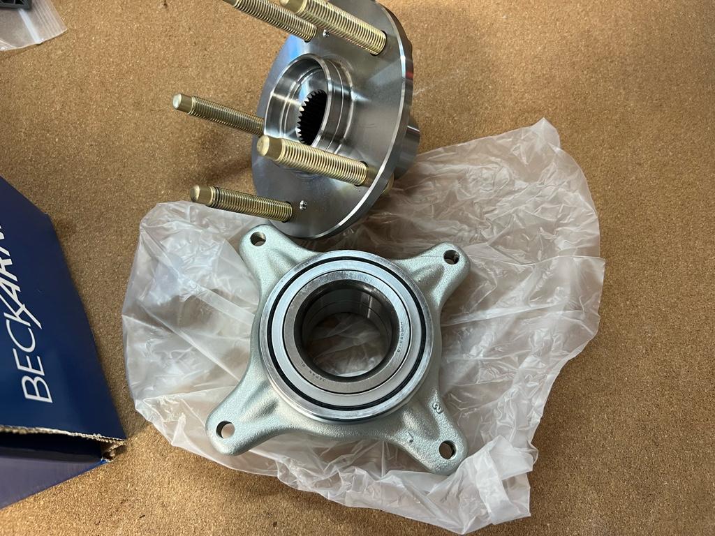
I had a local place press them together. They insisted on putting the hubs in the freezer for an hour to shrink them a bit. Cool, just meant I had to leave and come back. Then pressed together:
Axle nuts: the struggle
The painful part. This was hard. These axle nuts were definitely the hardest bolt / nut I've ever had to break loose. I've done tons of swaps into rusty AF civics, pulled plenty of knuckles at junkyards with basic tools, and never had to fight with an axle nut like this. It took me like 6 weeks trying on and off, buying tools, waiting for tools to arrive, trying again, buying more tools, etc.
I started with stuff I already had. I soaked them in pb blaster, then I tried my trusty 600ftlb ingersol impact gun (90-100PSI on small 6 gal compressor), nope. It did break the axle bolts on the Audi (I'm a wheel-bearing-replacing machine these days), but wouldn't budge this nut. Next was 1/2 drive ratchet with alum cheater, felt like I'd break the ratchet. Maybe the 1/2 drive breaker bar? Felt like I'd break the breaker bar:
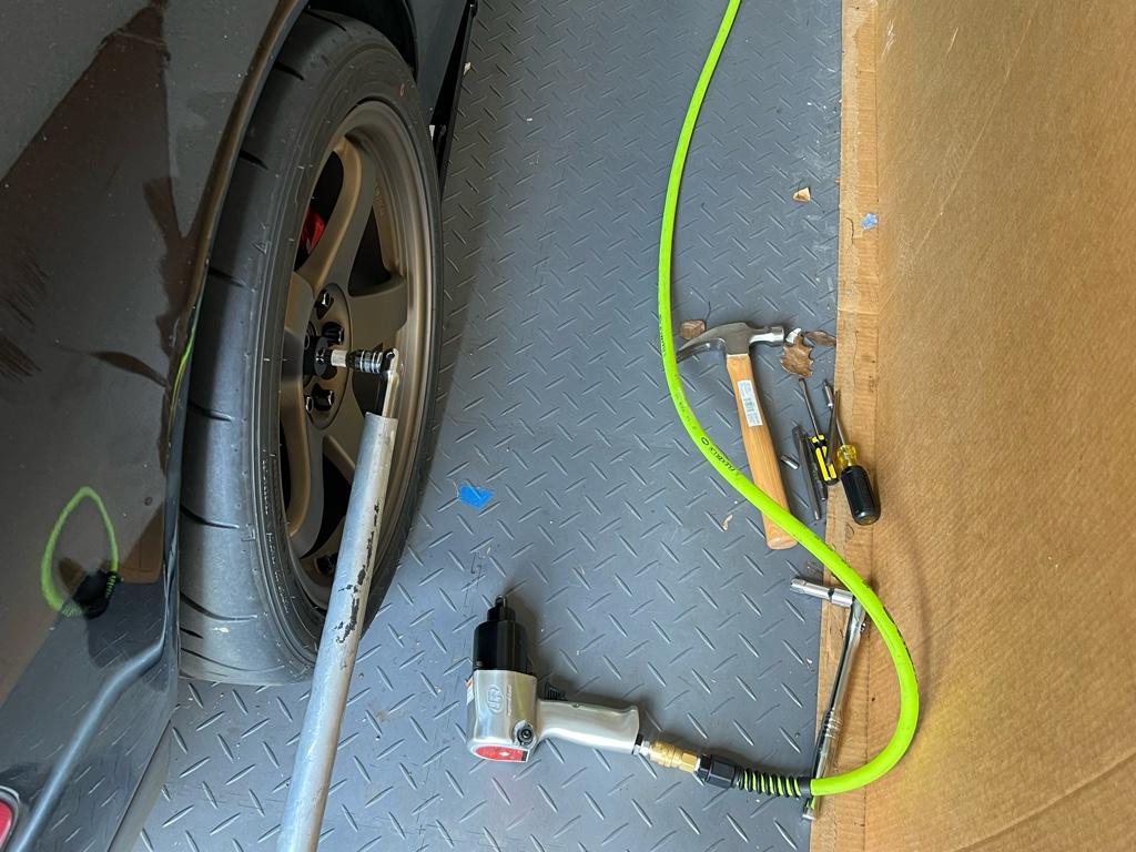
There began the cycle: Buy 3/4 drive breaker bar, try with alum cheater. Bend the F out of the aluminum cheater bar. Get 3' steel pipe cheater, break 3/4 -> 1/2 reducer:

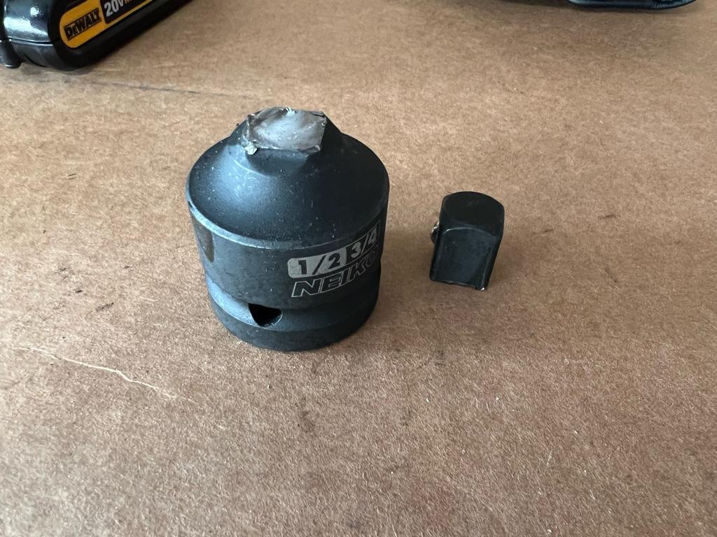
Buy several 3/4 drive sockets to find one that fits in the wheel + get a 5' cheater from the hardware store, nope. Torch the nut, nope. Bigger torch, nope.
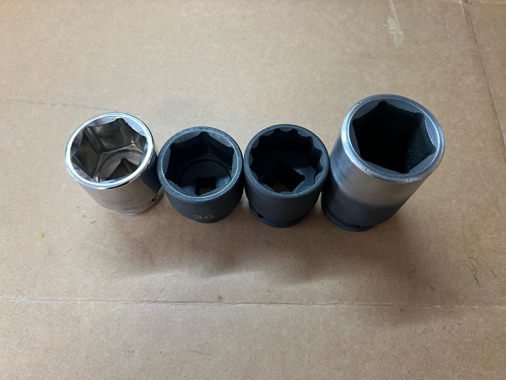
What about bigger impact guns?! I got an electric 3/4 drive impact and two harbor freight impact guns.
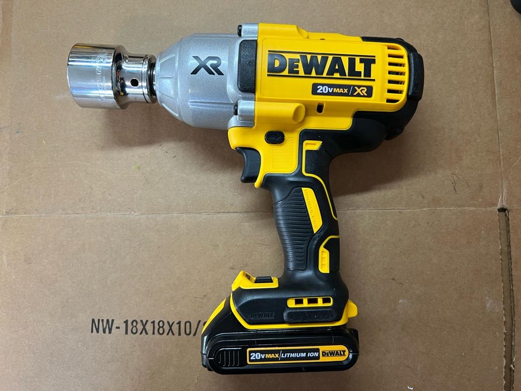
The electric one broke the left side nut loose!!!! WIN. But it couldn't touch the right side one. "Why is it so loud out there?!" my girlfriend asked.
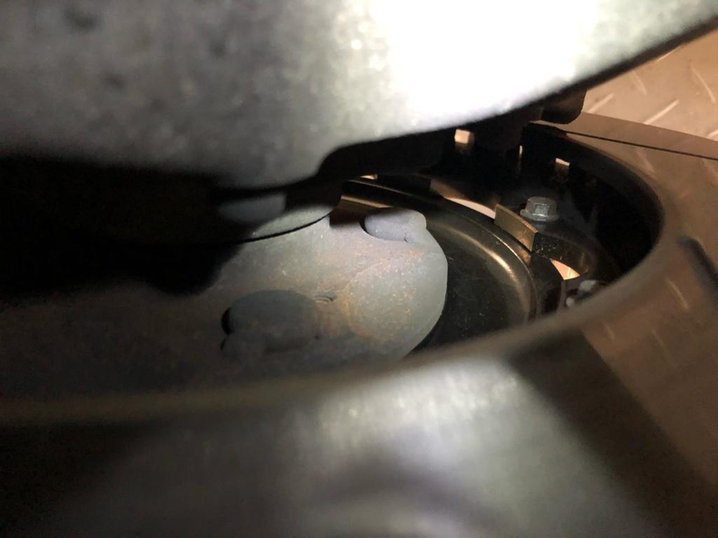
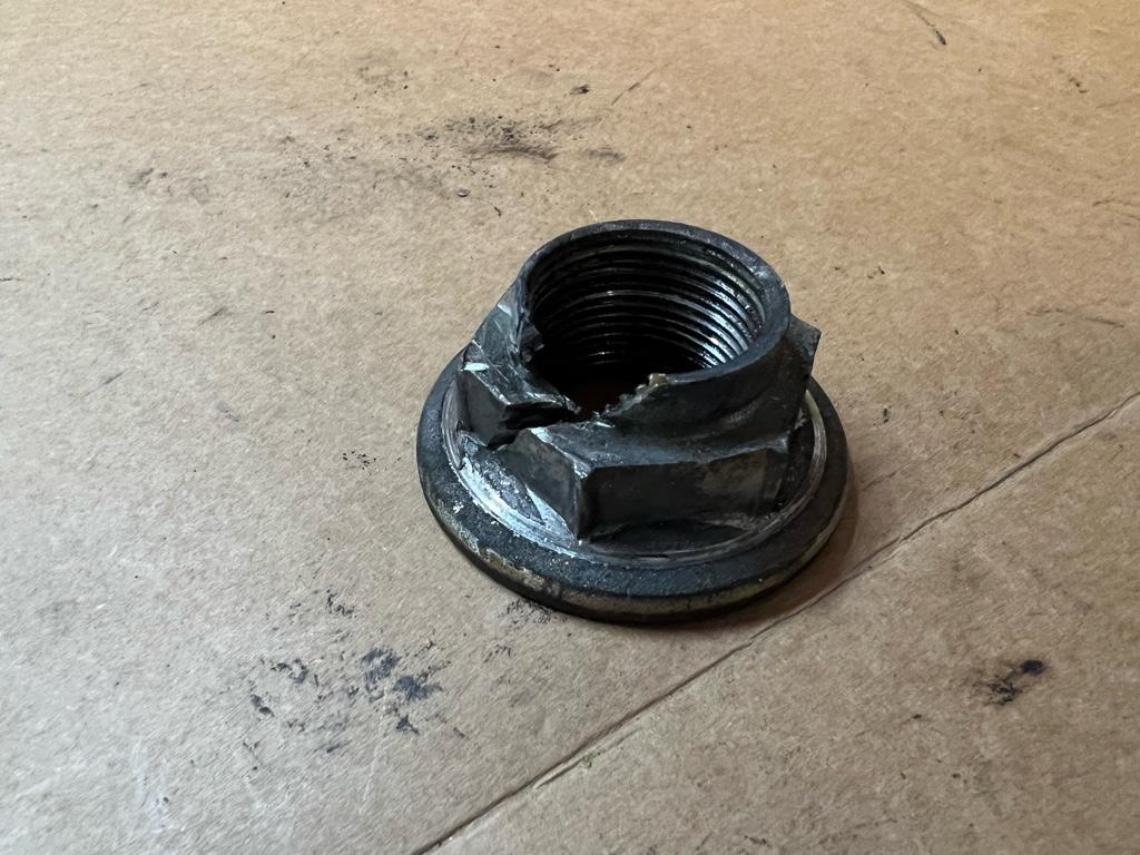
Drastic times, drastic measures, you know? I had read of someone cutting theirs then smacking it with a chisel to weaken it, then it came right off. I used a cutoff wheel on the dremel in an attempt to follow in his footsteps. I couldn't get the cutoff wheel deep enough into the flange without messing up the hub or the threads. In the end, it didnt work. Even with heat, both impacts, and the 5' cheater 1' off the breaker bar, nothing worked
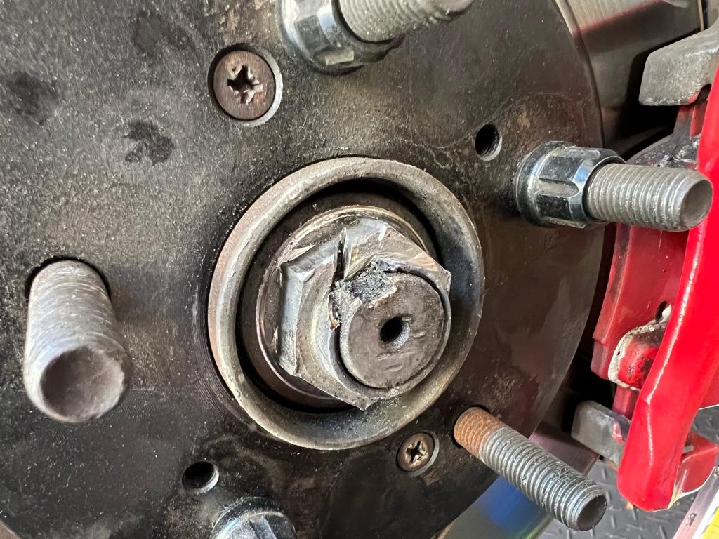
I broke down and took it to a local garage. After more than like $700 in tools and so so many hours, the solution was 15 min and $20. [emoji2357]
They got it loose with a beefcake 2600ftlb-claimed 1/2 drive impact gun. Their 3/4" gun also didn't do anything, even the bertha 1/2 drive that finally got it took probably 30 seconds to a minute of full-on impact.
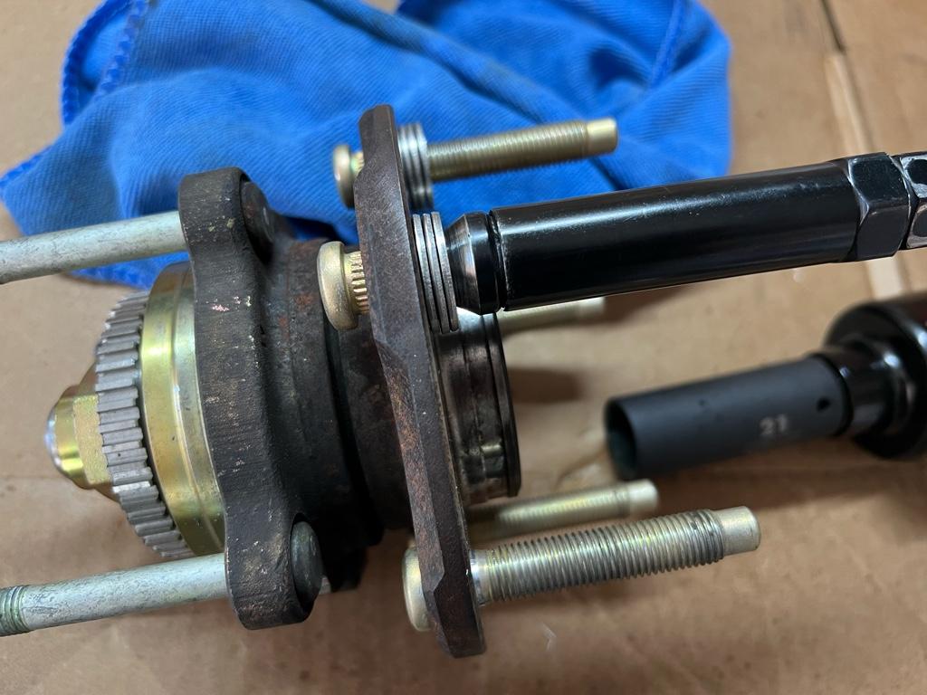
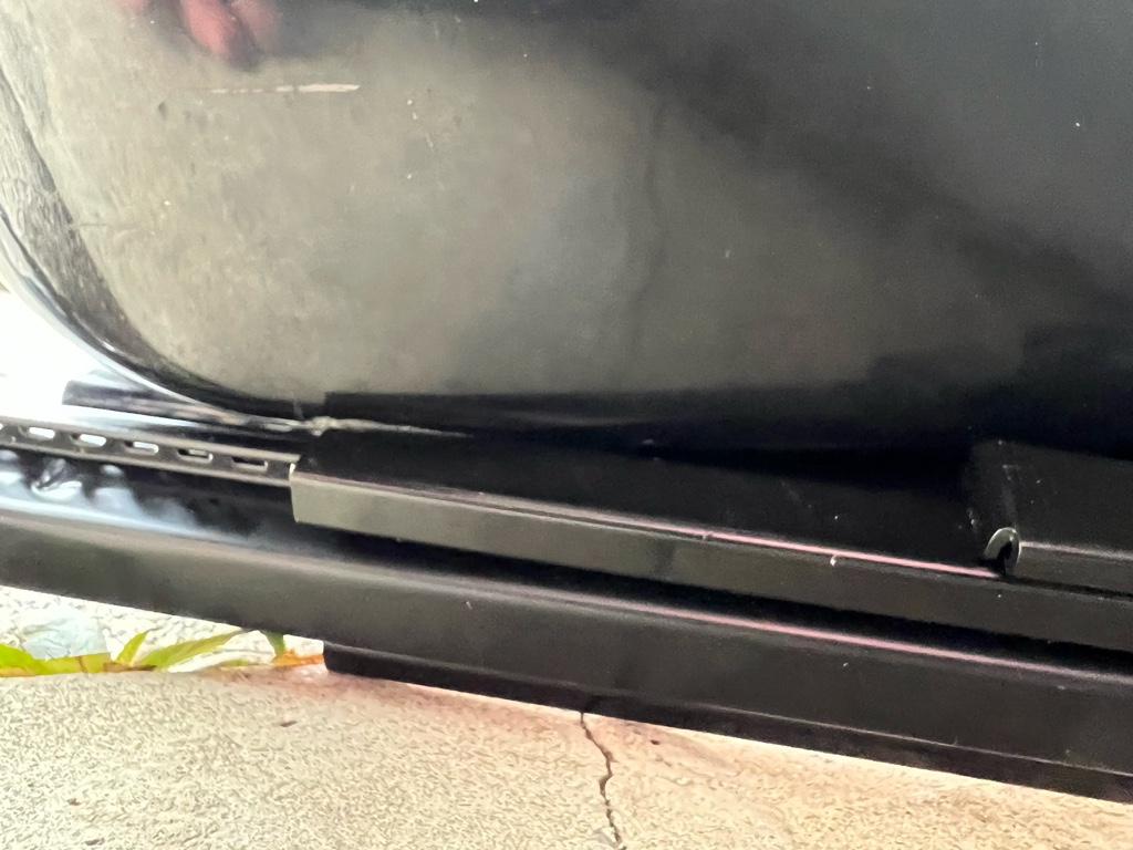
You can see how gathered the metal in the corners are from all the impact attempts
Install!!
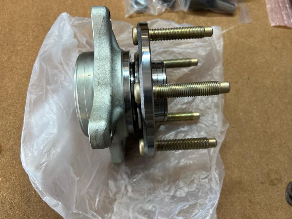
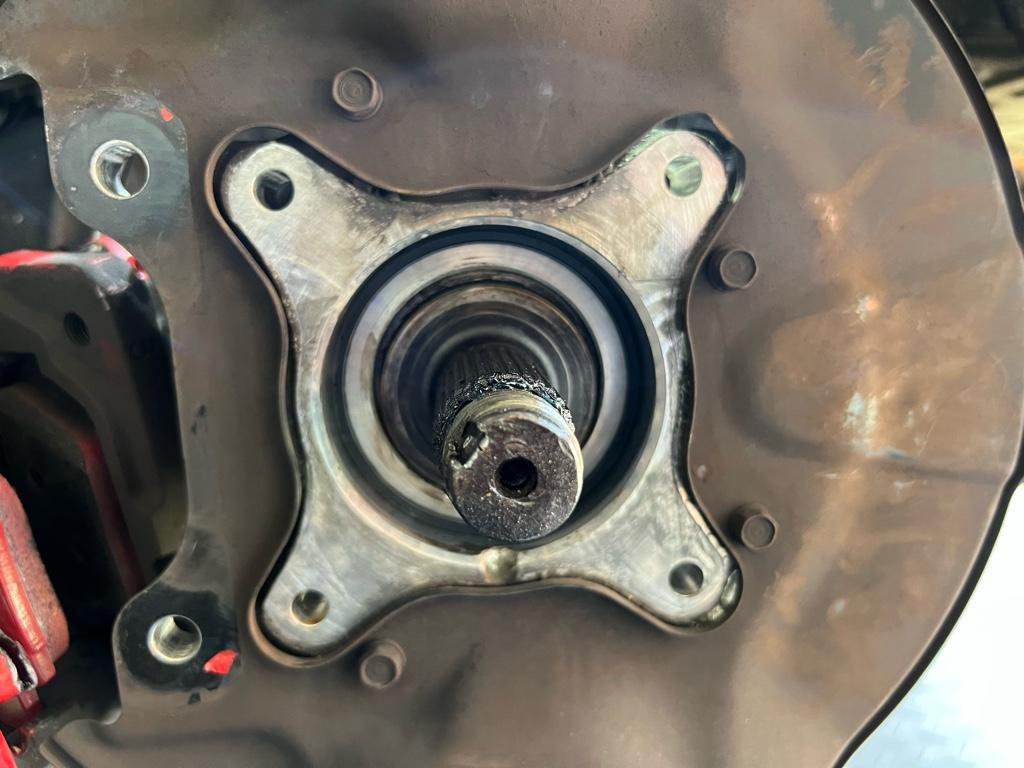
With the axle nuts off, the job was super easy. The splines were greased and there was no corrosion on the bearing-to-knuckle areas. Each side took me about an hour from pulling the wheel off to putting it back on with fresh hubs.
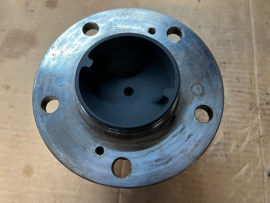
Left side old hub
Then off. I bought new seals shown in the parts diagram, but it was unclear where they went until I pulled off the old hubs. You can see the seals here up against the knuckle
After some cleaning, the old bearing and its seal.
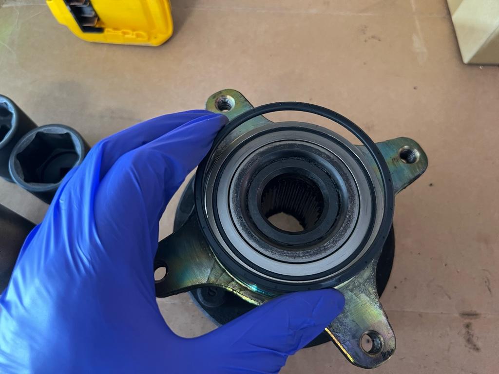
Ok, new one on
Then back together
The right side was similar
Once I had them done, I torqued the axle nuts and drove the car a bit with unstaked nuts. Then brought it back home, torqued them again (they didnt move) and staked them.
Fin!
So glad those are done! I'm taking the car to a "Rally" this weekend with a bunch of other old cars. In preparation, I went out for a long shakedown on Sunday. Happy to report that the car is feeling really really solid. I've been tinkering with a few driver position changes between axle nut battles. It's really starting to feel like mine!
The rear wheel bearings were considerably more difficult than the front due to axle nut pain.
Unlike the fronts, I managed to get all new parts. For the bearings, I went with Beck & Arnley (PN 051-4070) as they use NTN bearings just like OEM. Amayama had the new rear hubs, which was fortunate, then the same ARP studs as the front.
I had to knock out the OE studs. A lugnut on the end of the lug, a couple of washers, and a hammer did the trick.
Then I started the ARP studs with the ratchet.
But I could only get them like 1/2 way by hand. I used the impact gun method just like with the fronts to seat them. Here's the hubs and bearings ready to be pressed together:
I had a local place press them together. They insisted on putting the hubs in the freezer for an hour to shrink them a bit. Cool, just meant I had to leave and come back. Then pressed together:
Axle nuts: the struggle
The painful part. This was hard. These axle nuts were definitely the hardest bolt / nut I've ever had to break loose. I've done tons of swaps into rusty AF civics, pulled plenty of knuckles at junkyards with basic tools, and never had to fight with an axle nut like this. It took me like 6 weeks trying on and off, buying tools, waiting for tools to arrive, trying again, buying more tools, etc.
I started with stuff I already had. I soaked them in pb blaster, then I tried my trusty 600ftlb ingersol impact gun (90-100PSI on small 6 gal compressor), nope. It did break the axle bolts on the Audi (I'm a wheel-bearing-replacing machine these days), but wouldn't budge this nut. Next was 1/2 drive ratchet with alum cheater, felt like I'd break the ratchet. Maybe the 1/2 drive breaker bar? Felt like I'd break the breaker bar:
There began the cycle: Buy 3/4 drive breaker bar, try with alum cheater. Bend the F out of the aluminum cheater bar. Get 3' steel pipe cheater, break 3/4 -> 1/2 reducer:
Buy several 3/4 drive sockets to find one that fits in the wheel + get a 5' cheater from the hardware store, nope. Torch the nut, nope. Bigger torch, nope.
What about bigger impact guns?! I got an electric 3/4 drive impact and two harbor freight impact guns.
The electric one broke the left side nut loose!!!! WIN. But it couldn't touch the right side one. "Why is it so loud out there?!" my girlfriend asked.
Drastic times, drastic measures, you know? I had read of someone cutting theirs then smacking it with a chisel to weaken it, then it came right off. I used a cutoff wheel on the dremel in an attempt to follow in his footsteps. I couldn't get the cutoff wheel deep enough into the flange without messing up the hub or the threads. In the end, it didnt work. Even with heat, both impacts, and the 5' cheater 1' off the breaker bar, nothing worked
I broke down and took it to a local garage. After more than like $700 in tools and so so many hours, the solution was 15 min and $20. [emoji2357]
They got it loose with a beefcake 2600ftlb-claimed 1/2 drive impact gun. Their 3/4" gun also didn't do anything, even the bertha 1/2 drive that finally got it took probably 30 seconds to a minute of full-on impact.
You can see how gathered the metal in the corners are from all the impact attempts
Install!!
With the axle nuts off, the job was super easy. The splines were greased and there was no corrosion on the bearing-to-knuckle areas. Each side took me about an hour from pulling the wheel off to putting it back on with fresh hubs.
Left side old hub
Then off. I bought new seals shown in the parts diagram, but it was unclear where they went until I pulled off the old hubs. You can see the seals here up against the knuckle
After some cleaning, the old bearing and its seal.
Ok, new one on
Then back together
The right side was similar
Once I had them done, I torqued the axle nuts and drove the car a bit with unstaked nuts. Then brought it back home, torqued them again (they didnt move) and staked them.
Fin!
So glad those are done! I'm taking the car to a "Rally" this weekend with a bunch of other old cars. In preparation, I went out for a long shakedown on Sunday. Happy to report that the car is feeling really really solid. I've been tinkering with a few driver position changes between axle nut battles. It's really starting to feel like mine!
Last edited:
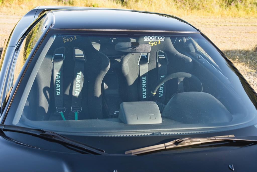
New harnesses
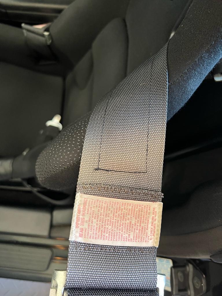
I installed some spankin new harnesses a couple weeks ago. It was time. The harnesses that came with the car were old enough to talk back--they expired in 2013. On top of that, the driver's harness was a good bit faded from the sun, which, from what I've read substantially weakens the webbing. Even more insult to injury was that they never did fit me so well. The old harnesses had 3" lap belts and I've never really been able to get the lap belts tight. To pile on even more, the sub belts are pretty uncomfortable, take that!
Old
Faded
Decisions
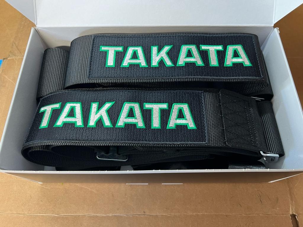
I wanted a 6 point 3x2 setup: 3" shoulder belts and 2" lap belts. The main benefit there is that a 2" lap belt is easier to cinch down and they apparently sit better on a human's hips. Turns out I am human, so a fitting feature indeed.
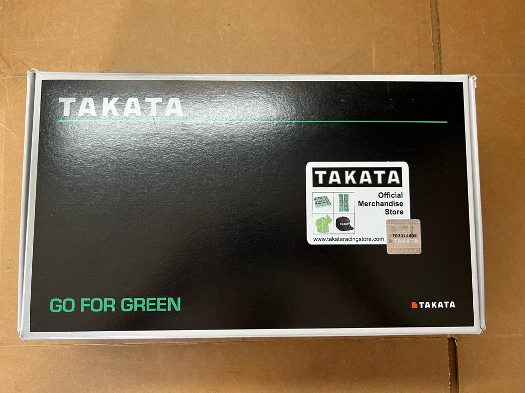
Of all the 3x2s out there, I narrowed it down to two choices: Schroth Profi 6 point 3x2 or Takata 6 point 3x2. After some more research, it turns out they are actually pretty much the same thing. Schroth makes Takata harnesses, and both harnesses have all the same features. One small difference is the Schroth branded harnesses have an option of pull-up lap belts, the Takata harnesses are all pull-downs.
I decided I wanted pull-downs, so in the end it came down to bling factor and color scheme, really important stuff. Do I pay $100 extra per harness for JDM Fashion? I agonized, I waffled. I am practical (I think), so Schroth it is, right? Ultimately irrationality won out and I got the Takata harnesses (expire 2027).
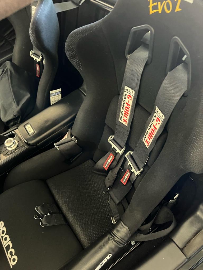
They were straightforward to install and adjust. The sub and shoulder belts are wrap in. The lap belts bolt to the harness bar; I used some of the G-Force hardware there cause the Takata hardware was all clip in.
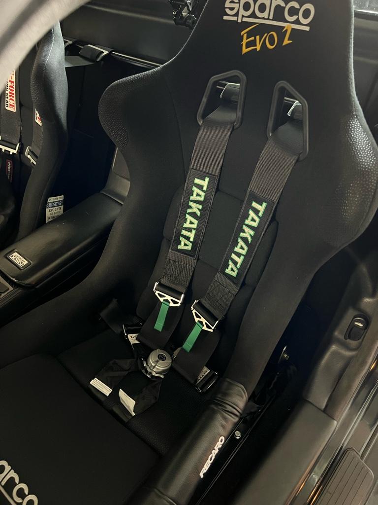
Now all I need are some bride gradient seats to complete the package, eh?
Impressions
They are a lot better. The new belts are more comfortable in the hips / crotch region, and I can, in fact, cinch the lap belts down way tight on my actual hips. The sub belts kind of fold and rest against your leg, not pinching any sensitive human hardware—great job engineers. The camlock is attached to the sub strap, which is a feature I didn't know I needed, but now I do. Because the lap belts are tighter, the shoulder belts go tighter too, so I feel more snug overall in the car. Yay improvements!
I installed some spankin new harnesses a couple weeks ago. It was time. The harnesses that came with the car were old enough to talk back--they expired in 2013. On top of that, the driver's harness was a good bit faded from the sun, which, from what I've read substantially weakens the webbing. Even more insult to injury was that they never did fit me so well. The old harnesses had 3" lap belts and I've never really been able to get the lap belts tight. To pile on even more, the sub belts are pretty uncomfortable, take that!
Old
Faded
Decisions
I wanted a 6 point 3x2 setup: 3" shoulder belts and 2" lap belts. The main benefit there is that a 2" lap belt is easier to cinch down and they apparently sit better on a human's hips. Turns out I am human, so a fitting feature indeed.
Of all the 3x2s out there, I narrowed it down to two choices: Schroth Profi 6 point 3x2 or Takata 6 point 3x2. After some more research, it turns out they are actually pretty much the same thing. Schroth makes Takata harnesses, and both harnesses have all the same features. One small difference is the Schroth branded harnesses have an option of pull-up lap belts, the Takata harnesses are all pull-downs.
I decided I wanted pull-downs, so in the end it came down to bling factor and color scheme, really important stuff. Do I pay $100 extra per harness for JDM Fashion? I agonized, I waffled. I am practical (I think), so Schroth it is, right? Ultimately irrationality won out and I got the Takata harnesses (expire 2027).
They were straightforward to install and adjust. The sub and shoulder belts are wrap in. The lap belts bolt to the harness bar; I used some of the G-Force hardware there cause the Takata hardware was all clip in.
Now all I need are some bride gradient seats to complete the package, eh?
Impressions
They are a lot better. The new belts are more comfortable in the hips / crotch region, and I can, in fact, cinch the lap belts down way tight on my actual hips. The sub belts kind of fold and rest against your leg, not pinching any sensitive human hardware—great job engineers. The camlock is attached to the sub strap, which is a feature I didn't know I needed, but now I do. Because the lap belts are tighter, the shoulder belts go tighter too, so I feel more snug overall in the car. Yay improvements!
Lower seat
I've been messing with the seating position a little bit. A couple months ago I signed up for an autox and bought an SA helmet. I hardly fit in the car as is (6'1" mostly torso), as expected I 100% didn't fit in the car with the helmet on. Even way slouched with no seat pads, the helmet was pinned against the headliner.
I have the SoS "low" seat rails but the rear of the seats were not on lowest hole. The seats are Sparco Evo 2s are on the wide side and the rear of them interferes with the rail on the lowest setting.
I took some terrible photos, you can kind of see how if it were lower, it'd hit the rail
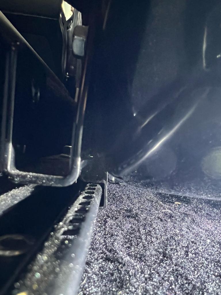
With the seat out, I tried to figure out where it interfered
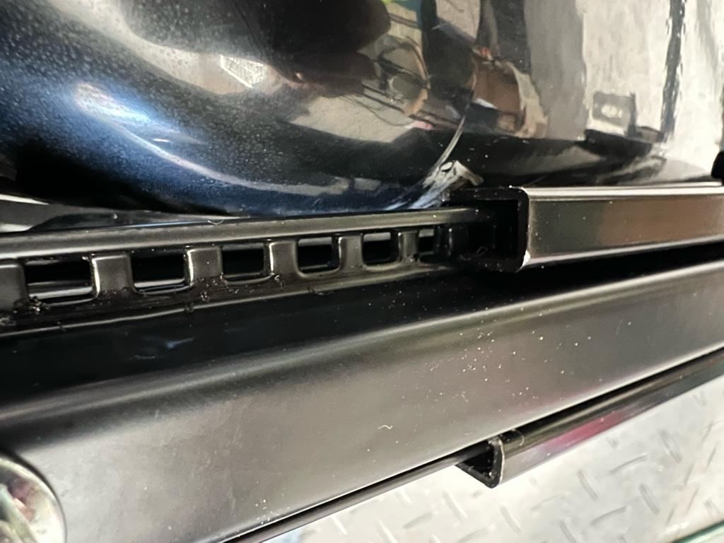
Well after a whole lot of die grinding on the rail, I managed to get it down to the lowest hole. Again, a terrible photo, hopefully it kind of makes sense
I only did the driver's side, so it looks a lot lower than the passenger seat:
I fit a lot better in the car, but the helmet still hits the headliner with the seat pads in. Taking them out works pretty well though. The autox day didn't happen for me, that morning ended up being oddly crazy rainy.
Extendo steering wheel
The seat was lower, yay, but only the rear of the seat was lowered. I was more reclined and further from the steering wheel. Dont want to be driving with my fingertips! Move the seat up? Knees all scrunched up, nope.
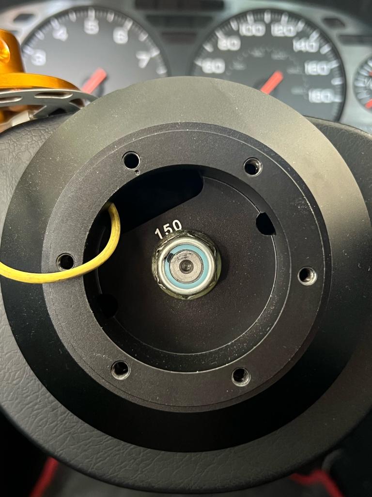
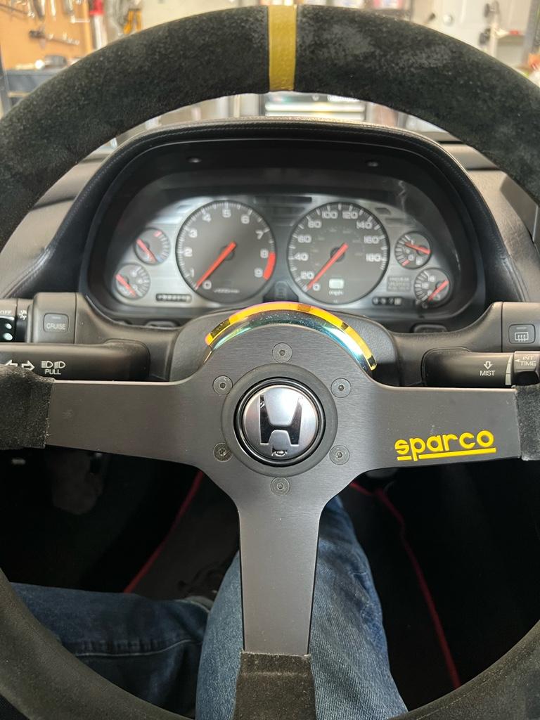
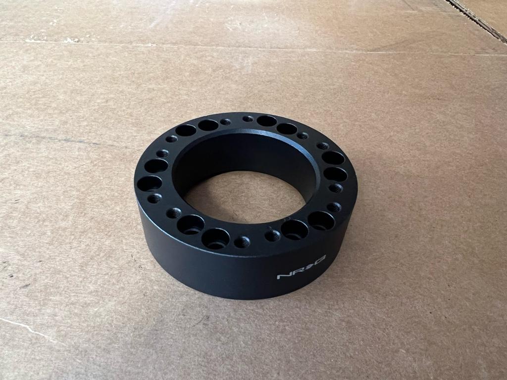
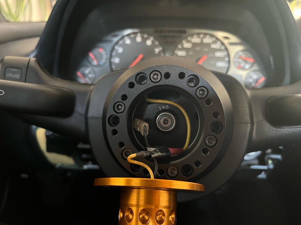
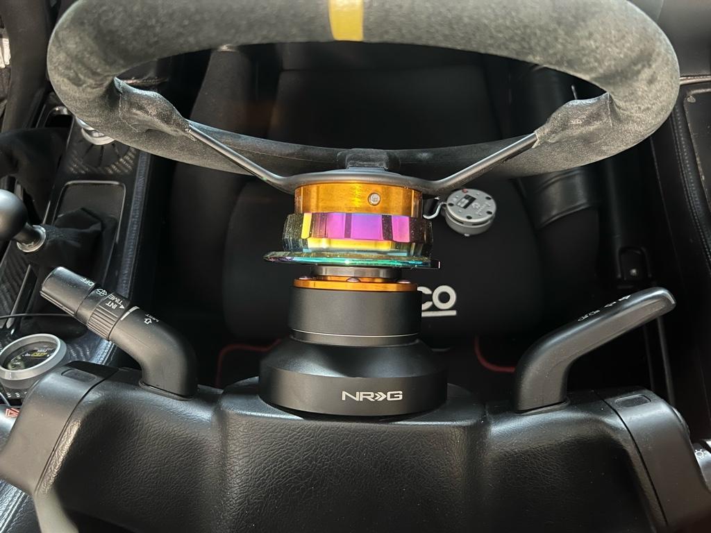
I got a 1" steering wheel spacer:
I had to wire wheel some finish away to get the horn to work, once that was done, I bolted it up. The ground ring is between the hub and the spacer:
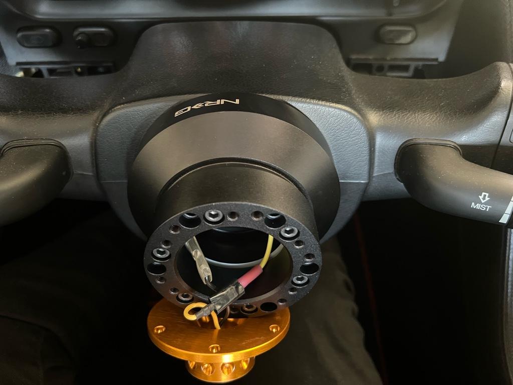
I had to move the hub over 2 splines to center the wheel
All put together
With these changes and the new harnesses the car fits me so much better than previously.
I should probably lower the passenger seat so they look the same, but it hardly fits in the car as is. I might end up with new, narrower seats before I fight with the existing one.
I've been messing with the seating position a little bit. A couple months ago I signed up for an autox and bought an SA helmet. I hardly fit in the car as is (6'1" mostly torso), as expected I 100% didn't fit in the car with the helmet on. Even way slouched with no seat pads, the helmet was pinned against the headliner.
I have the SoS "low" seat rails but the rear of the seats were not on lowest hole. The seats are Sparco Evo 2s are on the wide side and the rear of them interferes with the rail on the lowest setting.
I took some terrible photos, you can kind of see how if it were lower, it'd hit the rail
With the seat out, I tried to figure out where it interfered
Well after a whole lot of die grinding on the rail, I managed to get it down to the lowest hole. Again, a terrible photo, hopefully it kind of makes sense
I only did the driver's side, so it looks a lot lower than the passenger seat:
I fit a lot better in the car, but the helmet still hits the headliner with the seat pads in. Taking them out works pretty well though. The autox day didn't happen for me, that morning ended up being oddly crazy rainy.
Extendo steering wheel
The seat was lower, yay, but only the rear of the seat was lowered. I was more reclined and further from the steering wheel. Dont want to be driving with my fingertips! Move the seat up? Knees all scrunched up, nope.
I got a 1" steering wheel spacer:
I had to wire wheel some finish away to get the horn to work, once that was done, I bolted it up. The ground ring is between the hub and the spacer:
I had to move the hub over 2 splines to center the wheel
All put together
With these changes and the new harnesses the car fits me so much better than previously.
I should probably lower the passenger seat so they look the same, but it hardly fits in the car as is. I might end up with new, narrower seats before I fight with the existing one.
Last edited:
Rally
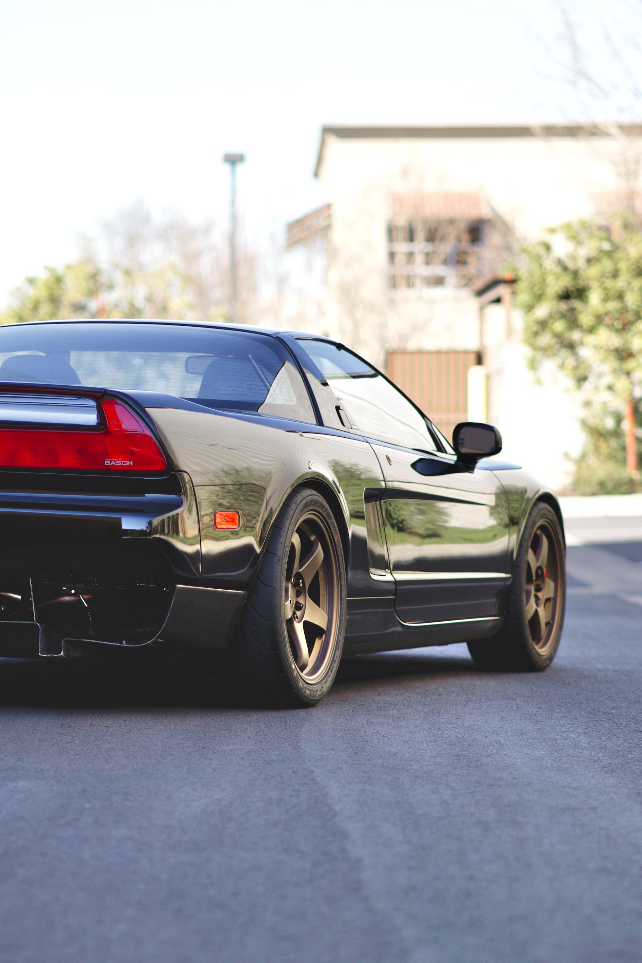
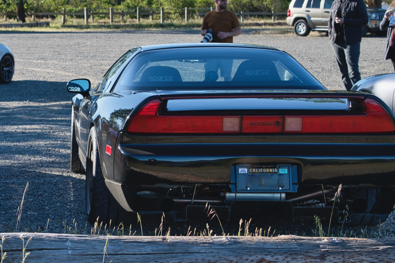
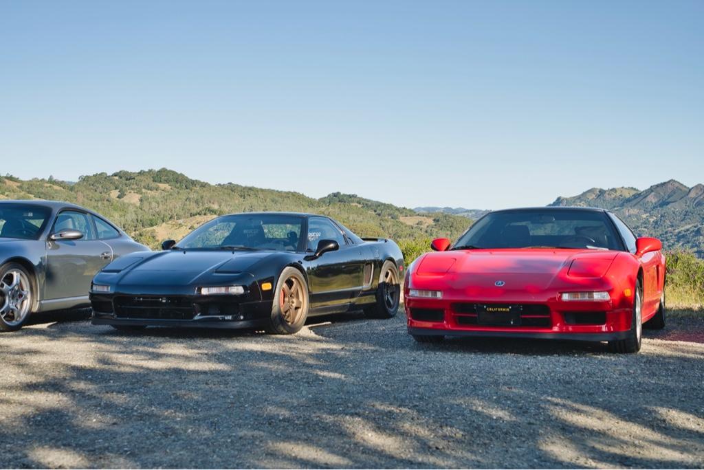
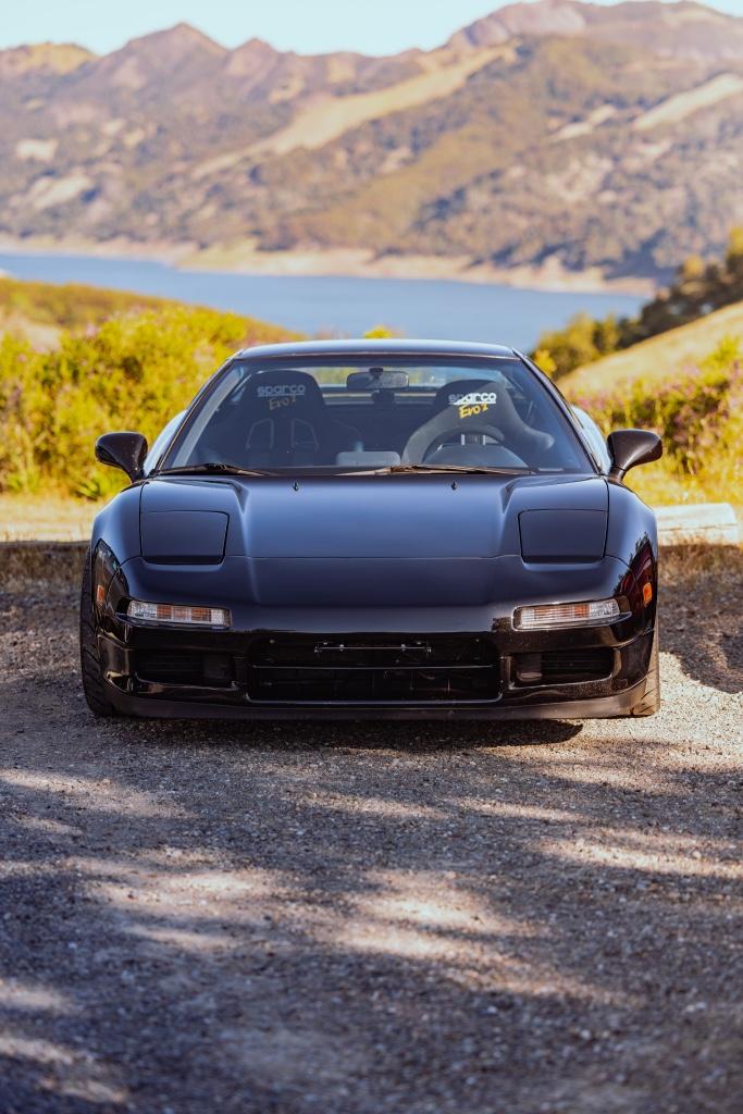
A couple weeks ago I took the car to a rally with breakfast club rally. It was super fun. The rallys are all on twisty roads somewhere in the north bay: Marin, Sonoma, and / or Napa counties. This one was in Sonoma and painfully local, the route came within a half mile of the house. I spent the morning chasing a couple 911s and a 308 (or 328, I can't tell).
If you're in the SF bay area, you should come to one! They do it every month. There were a lot of Porsches and BMWs, someone needs to offset the German with some Japanese vibes.
I took a couple pics, but not as many as I would have liked. There was one other NSX and we managed to stay together for some of it.
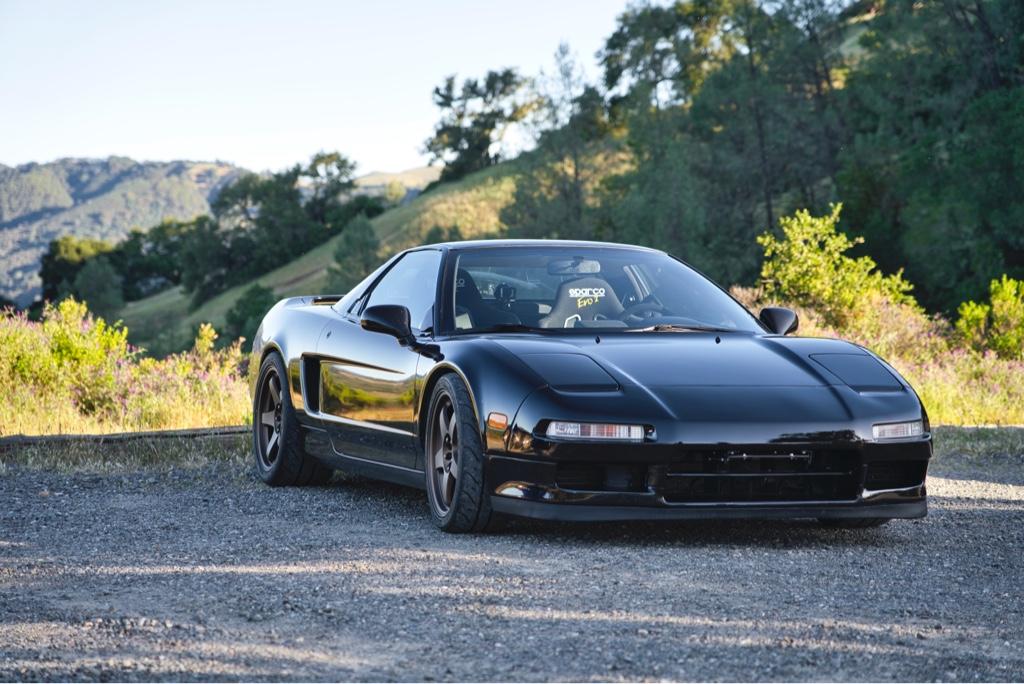
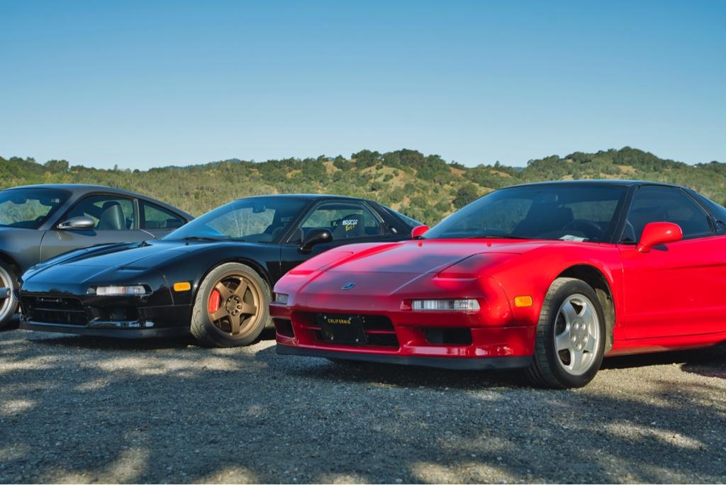
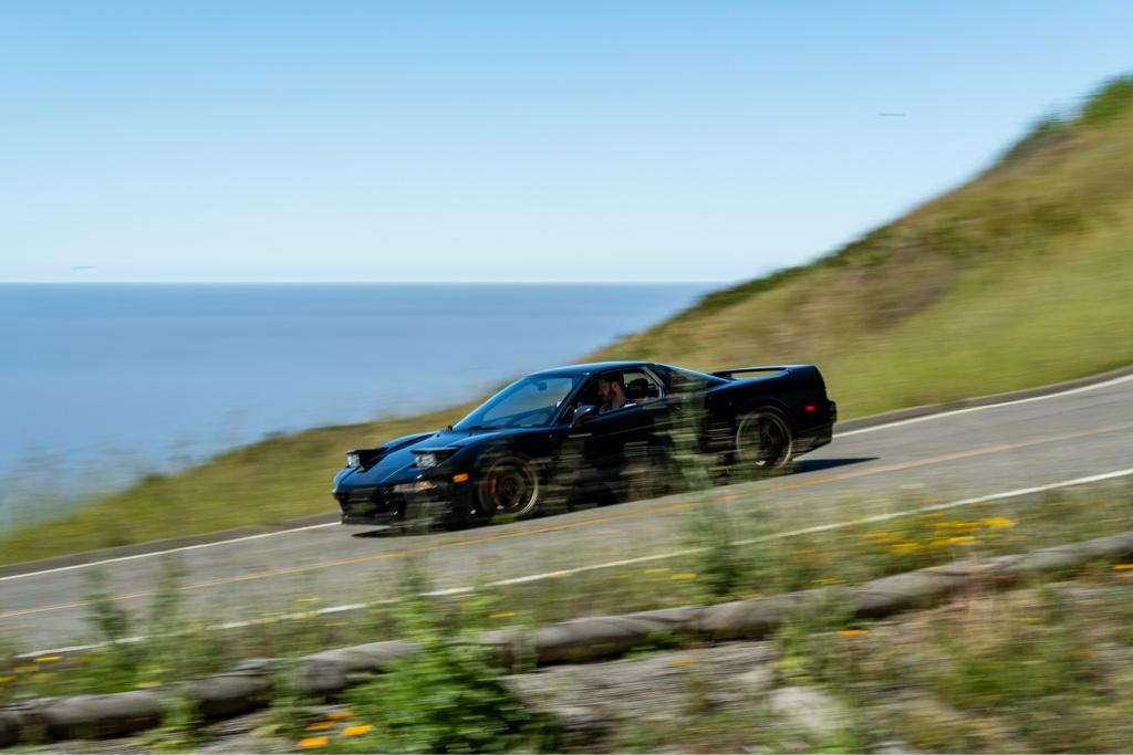
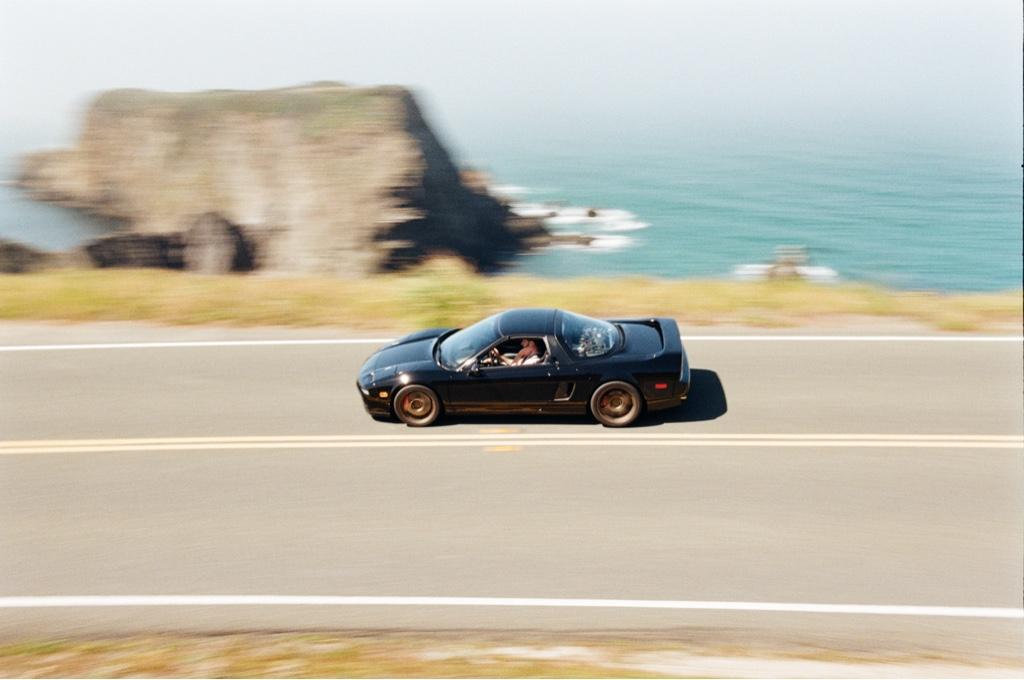
One really cool thing about this group is that they have 3 or 4 pro photographers at every event. They camp out on the route and take rollers of everyone. This event had 4 photographers: pics, more pics, even more pics, and omg more pics.
I got all the photos they took of my car. I especially love the real film photos. And it's cool to have rolling shots, first ones!
A couple weeks ago I took the car to a rally with breakfast club rally. It was super fun. The rallys are all on twisty roads somewhere in the north bay: Marin, Sonoma, and / or Napa counties. This one was in Sonoma and painfully local, the route came within a half mile of the house. I spent the morning chasing a couple 911s and a 308 (or 328, I can't tell).
If you're in the SF bay area, you should come to one! They do it every month. There were a lot of Porsches and BMWs, someone needs to offset the German with some Japanese vibes.
I took a couple pics, but not as many as I would have liked. There was one other NSX and we managed to stay together for some of it.
One really cool thing about this group is that they have 3 or 4 pro photographers at every event. They camp out on the route and take rollers of everyone. This event had 4 photographers: pics, more pics, even more pics, and omg more pics.
I got all the photos they took of my car. I especially love the real film photos. And it's cool to have rolling shots, first ones!
The rally in the last post started in the middle of Sonoma county, then took one road for 30 miles alllll the way out to the coast. The first 10 or so miles were amazing: very few straights, super smooth, technical sections, fast sections, and passing lanes. So good, very well suited to the car. That 308 was having trouble keeping up. It is probably one of the best driving roads in Northern California, super popular with motorcyclists.
The 2nd 10 mile stint were a little less amazing, skinnier and slightly rougher, but still usable and fun. From what I hear, motorcycles usually turn around at the end of this stretch.
The last 10 miles of this road were terrible, though. It was basically a 1 lane logging road paved in like the 80s. Crazy twisty through the redwoods, but also insanely bumpy, cracked, heavily patched, and really hard to see around all the blind corners. Effectively a paved rally stage, cool in the right car, but not cool in this one. I was [emoji51][emoji51] the whole time and holding up the pack of other rally-goers behind me.
That last 10 rally-stage miles convinced me that the suspension is too stiff. The car is currently on tein RA coilovers with 10k/12k rates. When I got home, I realized I’ve never bothered to adjust them, or even checked to see where they were adjusted to. I figured maybe I could tone them down a bit for future bumpy roads.
I checked the front dampers. There are 16 clicks of adjustment, and the fronts were 2 clicks up from full soft. Not much room to go softer. I went one click softer just for kicks.
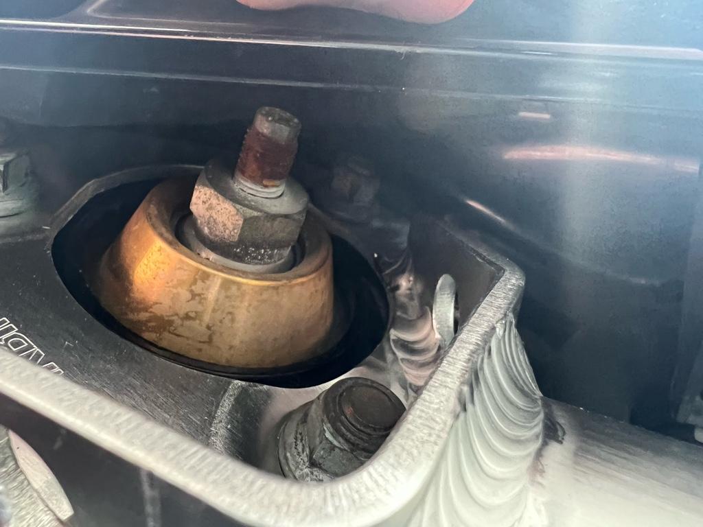
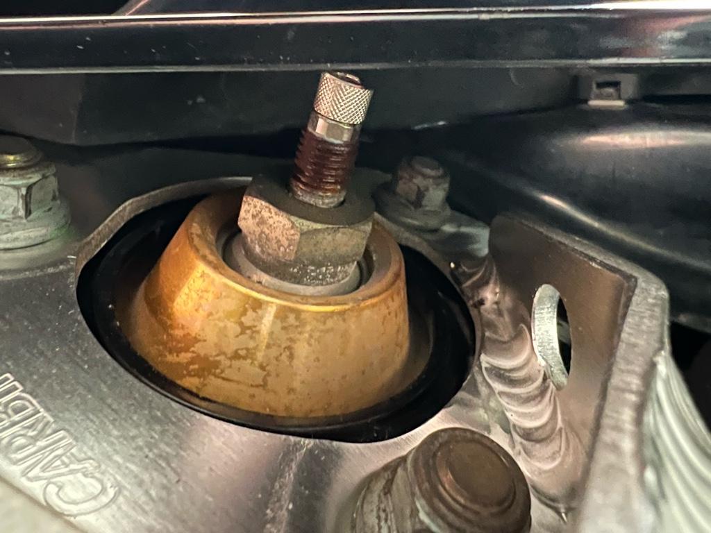
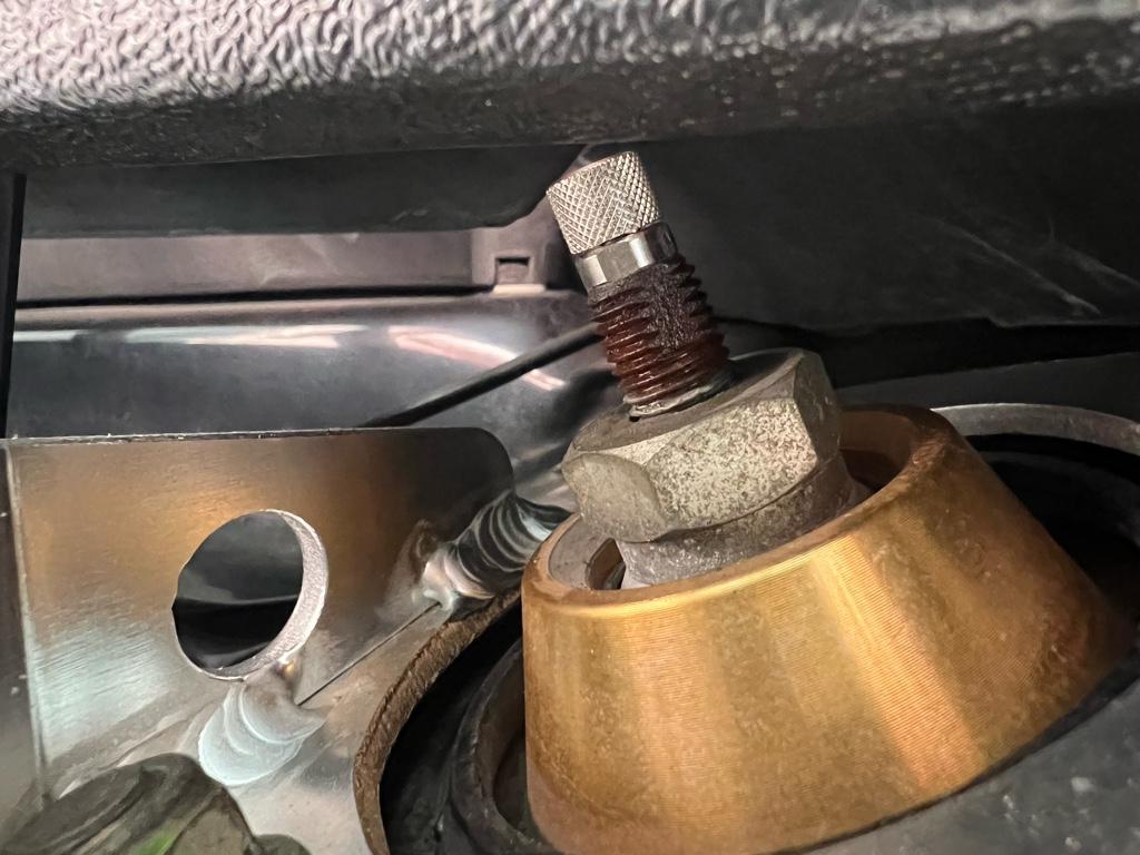
Then onto the rear. Story of my life, the rear adjusters didn’t move. They accept an Allen wrench on top, so I worked the left side adjuster back and forth with an Allen wrench. I managed to get 3 or 4 clicks of adjustment, win? It seemed like the left rear was set like 2 clicks from full hard (!!). Not ideal. Though it was kind of unclear where it was set cause I couldn’t get the full range of adjustment.
I didn’t want to break anything! So I chilled out and moved onto the right rear to do the same: work the Allen wrench back and forth, see how many clicks I get. A couple attempts in……snap! I broke the adjuster off. Oh Shiiiiiiit.

Oh man, I figured I bricked the damper. I don’t even know what setting it was set to. My options seemed like a rebuild or get new coilovers.
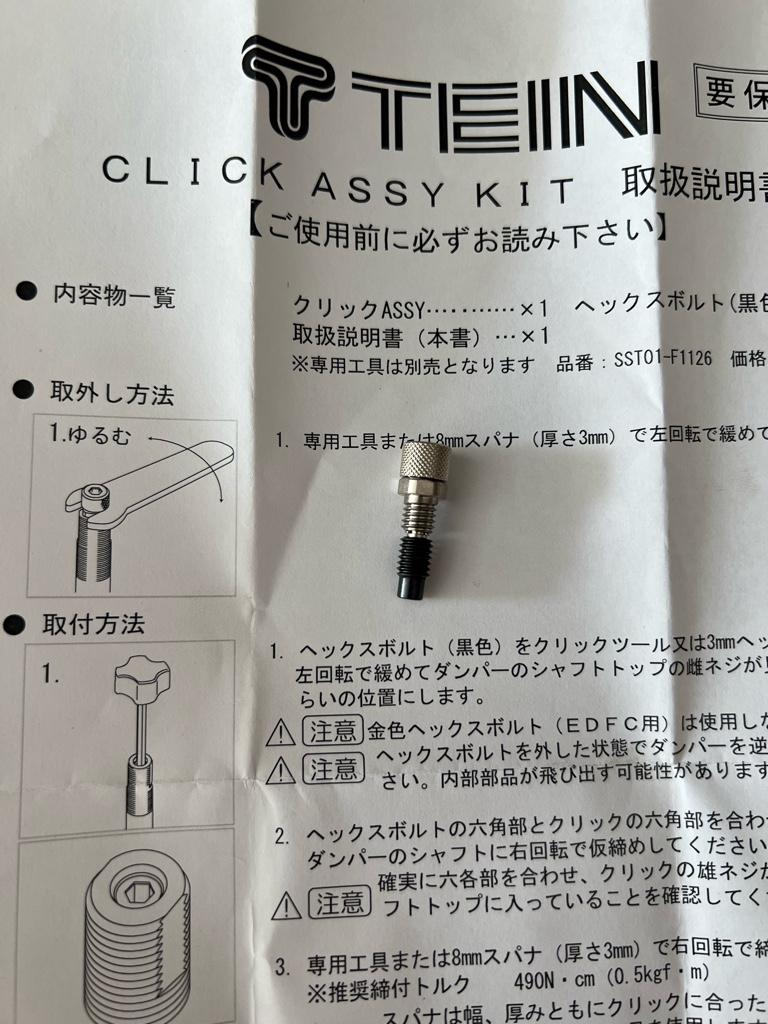
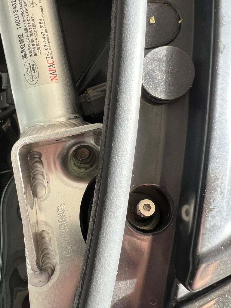
I emailed tein to see if they could fix them during a rebuild. They emailed back pretty quickly and said, yes they could fix them, but also this is common and you can probably fix them with a couple $10 parts. They sent me this blog post and told me I can buy the click adjusters on their site. Saweet. I bought a pair and the wrench. They came quickly:
First step was getting the old broken one out.
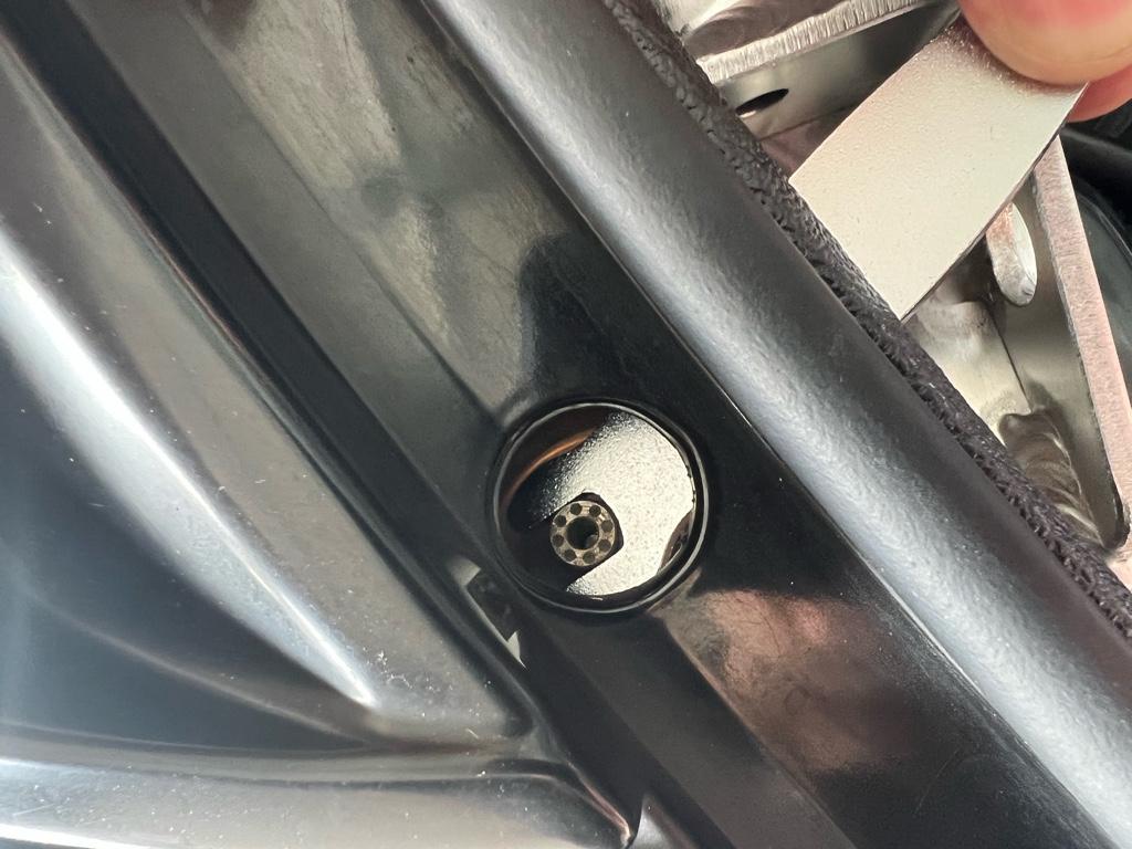
Once I had this collar out, I had to fish the broken piece out with a magnet. Almost there:
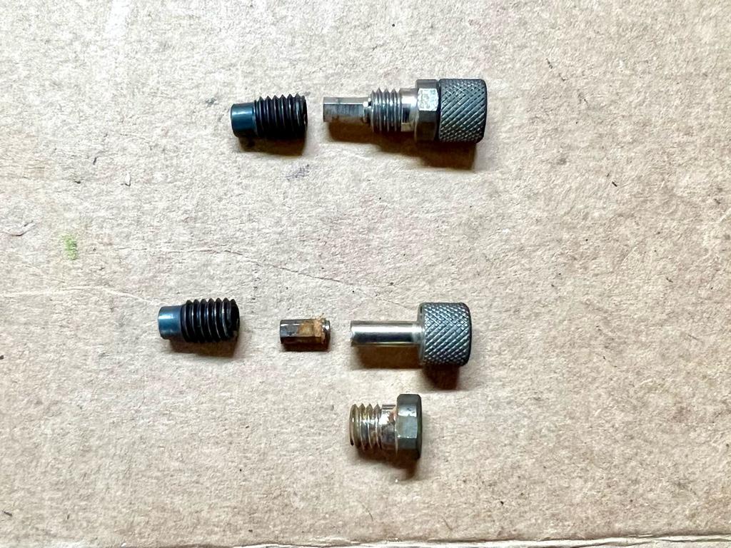
There is another little set screw down there in the shaft. The set screw pushes on a little metal pad to make the adjustment as you turn the clicker. This set screw was the problem. It had a bit of rust in the threads and was seized. A drop of wd40 and 10 minutes of waiting did the trick.
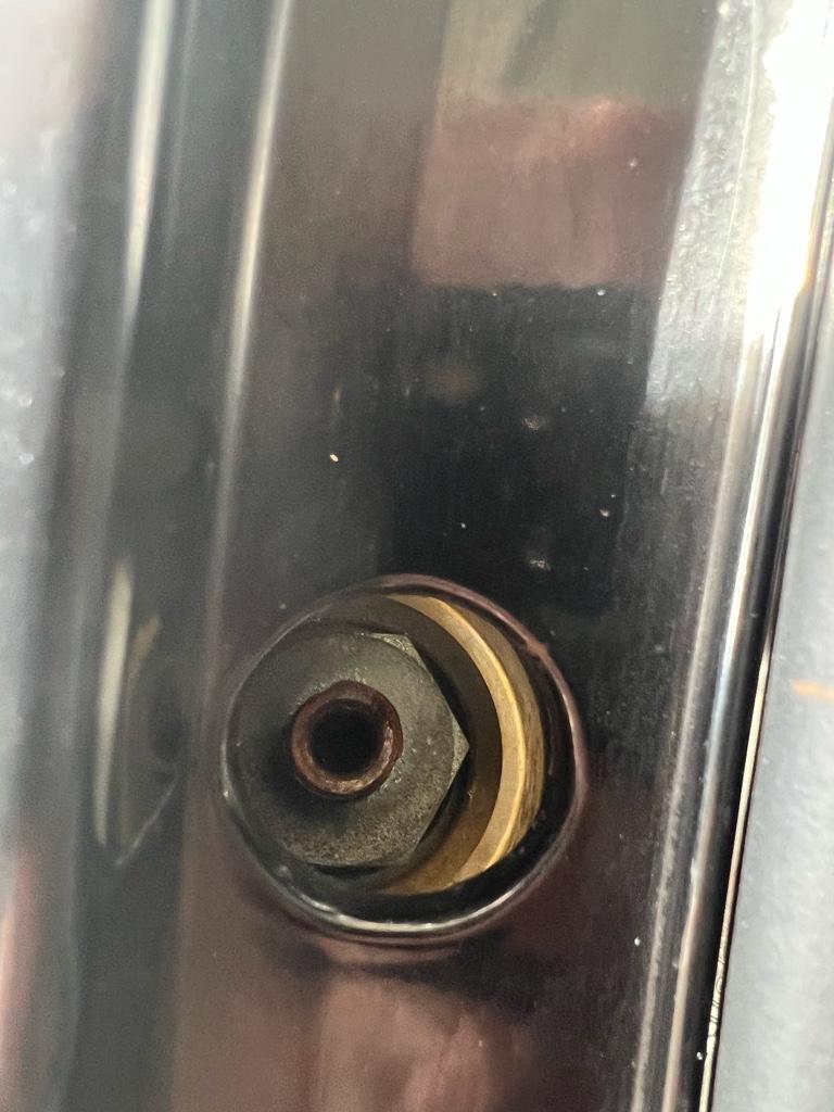
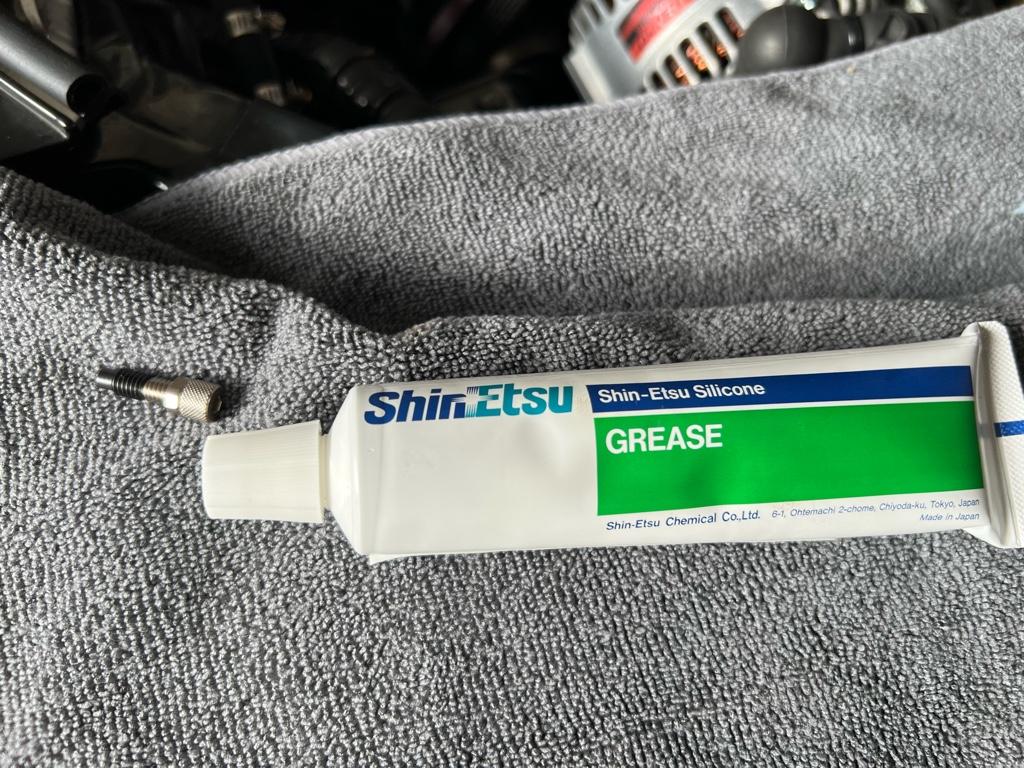
With it out, I greased the threads as the manual said and installed it. You can see the new set screw (black) in this pic, it fits into an Allen key at the end of the clicker (silver)
Then installed!
The left side had minimal adjustment range, so i did it too:
The old parts
Now the rears have full adjustment range, yay. I put them 2 clicks from full soft and took the car out. It’s definitely better! There is a 1 mile bumpy section to my favorite road that was less painful.
It still could be a little softer, though. I now have it in my head I should get new coilovers in an attempt to solve the stiffness. I’ve been doing a lot of reading and think I finally made a decision…
The 2nd 10 mile stint were a little less amazing, skinnier and slightly rougher, but still usable and fun. From what I hear, motorcycles usually turn around at the end of this stretch.
The last 10 miles of this road were terrible, though. It was basically a 1 lane logging road paved in like the 80s. Crazy twisty through the redwoods, but also insanely bumpy, cracked, heavily patched, and really hard to see around all the blind corners. Effectively a paved rally stage, cool in the right car, but not cool in this one. I was [emoji51][emoji51] the whole time and holding up the pack of other rally-goers behind me.
That last 10 rally-stage miles convinced me that the suspension is too stiff. The car is currently on tein RA coilovers with 10k/12k rates. When I got home, I realized I’ve never bothered to adjust them, or even checked to see where they were adjusted to. I figured maybe I could tone them down a bit for future bumpy roads.
I checked the front dampers. There are 16 clicks of adjustment, and the fronts were 2 clicks up from full soft. Not much room to go softer. I went one click softer just for kicks.
Then onto the rear. Story of my life, the rear adjusters didn’t move. They accept an Allen wrench on top, so I worked the left side adjuster back and forth with an Allen wrench. I managed to get 3 or 4 clicks of adjustment, win? It seemed like the left rear was set like 2 clicks from full hard (!!). Not ideal. Though it was kind of unclear where it was set cause I couldn’t get the full range of adjustment.
I didn’t want to break anything! So I chilled out and moved onto the right rear to do the same: work the Allen wrench back and forth, see how many clicks I get. A couple attempts in……snap! I broke the adjuster off. Oh Shiiiiiiit.
Oh man, I figured I bricked the damper. I don’t even know what setting it was set to. My options seemed like a rebuild or get new coilovers.
I emailed tein to see if they could fix them during a rebuild. They emailed back pretty quickly and said, yes they could fix them, but also this is common and you can probably fix them with a couple $10 parts. They sent me this blog post and told me I can buy the click adjusters on their site. Saweet. I bought a pair and the wrench. They came quickly:
First step was getting the old broken one out.
Once I had this collar out, I had to fish the broken piece out with a magnet. Almost there:
There is another little set screw down there in the shaft. The set screw pushes on a little metal pad to make the adjustment as you turn the clicker. This set screw was the problem. It had a bit of rust in the threads and was seized. A drop of wd40 and 10 minutes of waiting did the trick.
With it out, I greased the threads as the manual said and installed it. You can see the new set screw (black) in this pic, it fits into an Allen key at the end of the clicker (silver)
Then installed!
The left side had minimal adjustment range, so i did it too:
The old parts
Now the rears have full adjustment range, yay. I put them 2 clicks from full soft and took the car out. It’s definitely better! There is a 1 mile bumpy section to my favorite road that was less painful.
It still could be a little softer, though. I now have it in my head I should get new coilovers in an attempt to solve the stiffness. I’ve been doing a lot of reading and think I finally made a decision…
- Joined
- 22 November 2014
- Messages
- 77
Curious what your thoughts are on the coilovers you want to go with? I ended up with used JRZ I got a good deal on and got rebuilt, but I know what I would pick now. I can talk for hours on suspension and engines haha. I have a friend that owns a high end suspension shop back in TX where I moved from. He has an in house shock dyno and has tried tonsssss of shocks, so great to pick his brain. Where are you at in California? I just moved to Reno from TX, so not too far from Northern CA.
Similar threads
- Locked
- Replies
- 4
- Views
- 410