• Protip: Profile posts are public! Use Conversations to message other members privately. Everyone can see the content of a profile post.

Guidance Needed for CC Unit Not Blowing Any Air

Joined
10 December 2006
Messages
453
Location
GB
I've been reading through the forum but need some guidance for 1994.

-In 2012 I had BrianK repair my CCU.
-2 weeks ago I had my AC Freon refilled before summer started. However, in April & May, I noticed when I turned on the CCU sometimes it would take a few minutes before it would start blowing either hot air or AC.
-My CCU turns on, all buttons & lights work but no air is blowing. I can hear things turning off or on if I switch from 18c to 32c. I can hear vents moving when switching the air vent direction.
-When I did the CCU self test & pressed both buttons on my climate unit, the only thing that came on was "MODE"?

I checked the 30amp fuse under the hood in the larger more squarish (not rectangular box) & it looks fine.

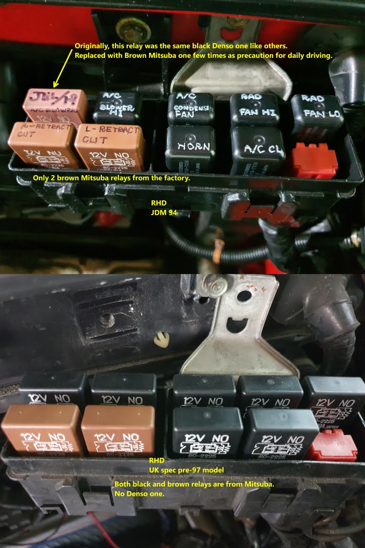
Here's where I need help. After some reading, it seems as though the layout of the under hood firewall Realy boxes are different for 97+.

It was suggested to use this picture from the service manual
Relay Box A.png

My fuse box actually has a melted fuse on the bottom right. It seems like this fuse is blower relay?


IMG-20230629-WA0004.jpg


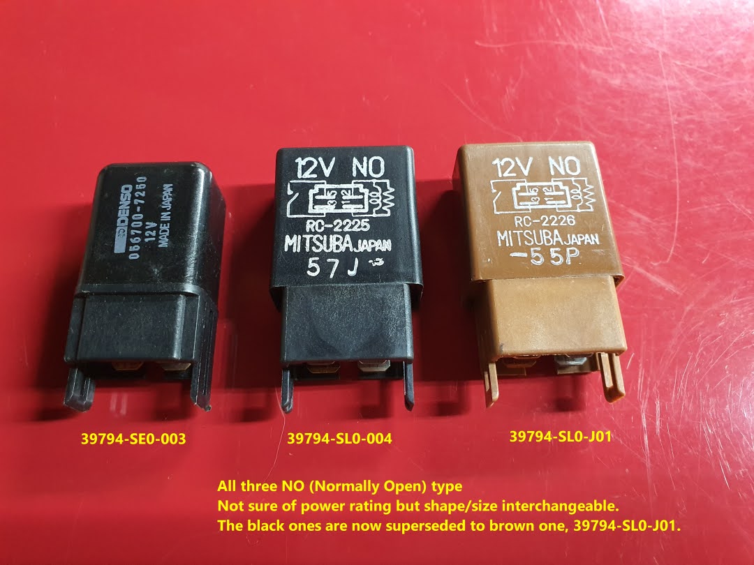
Once that fuse box is cleaned up, which relay would I be buying to replace that melted one?
39794-SL0-004?

The diagram is unclear to me on online parts websites.


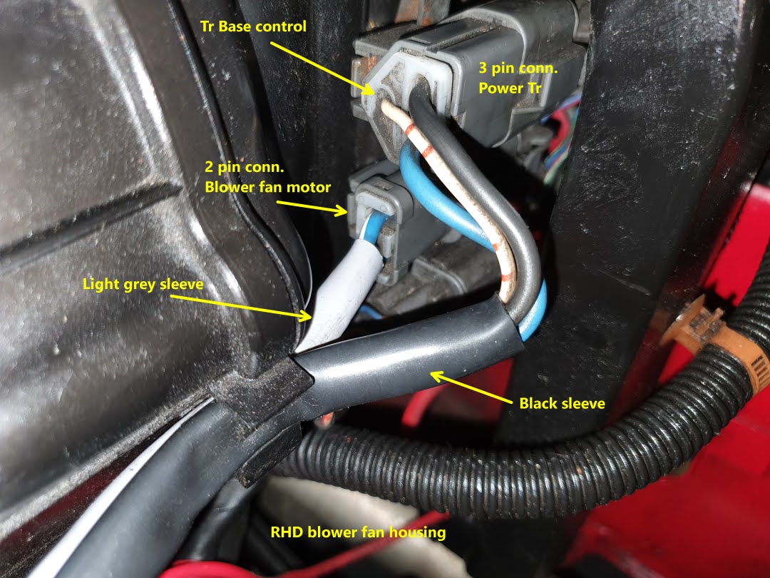
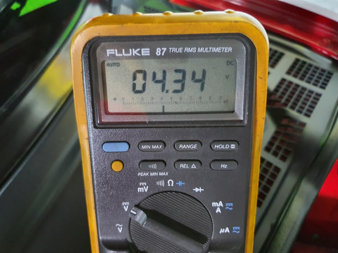
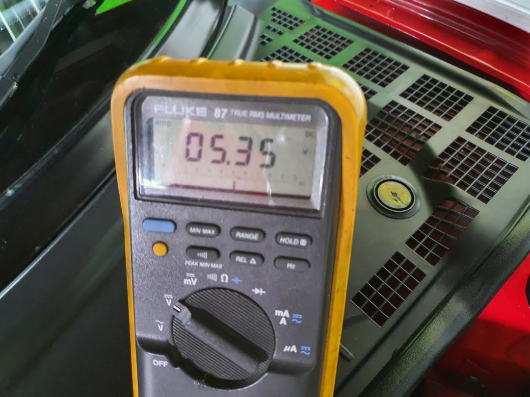
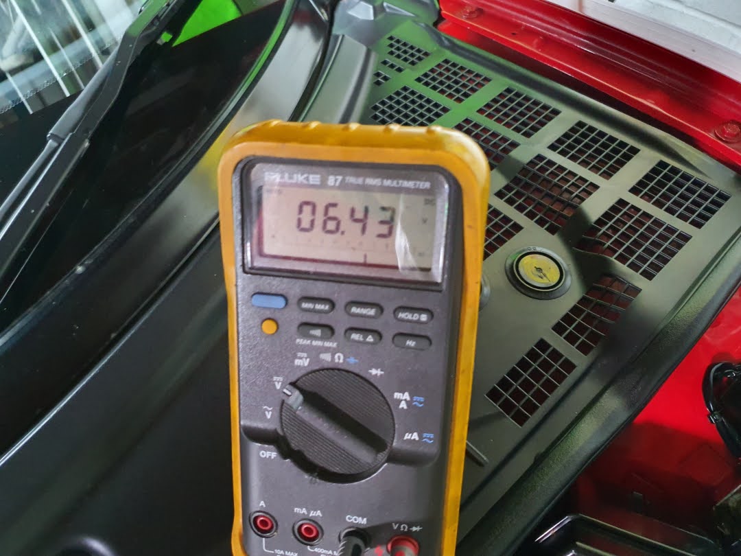
It also seems like I need to check the voltage going to the blower motor. I found old posts & the pictures are gone. Anybody have a picture of what wires/connections I need to check?
 
Last edited:
The relay locations did move around during the production years. This is the diagram from the 1992 Electrical Trouble Shooting Manual
Relay box A.jpg

and it shows that indeed it looks like your socket for the blower relay has been cooked.

As you note, the on-line parts catalogs are very confusing for this particular piece. My best guess from the Bernardi site is 39794-SE0-003 which looks like Denso 056700-7250. However, just to bugger you up Bernardi also lists 39794-SL0-J01 (Mitsuba) for the same part. Confirm with the actual Denso / Mitsuba part number on the relay case. If correct, the Denso and probably the Mitsuba is a dirt common relay. Rather than order the Acura part, go by the Denso or Mitsuba part number on the relay case. You will likely be able to find a much better price.

Your bigger problem is the melted socket at the bottom of the relay case. I have never had to deal with this particular problem so I don't know the construction of the relay boxes on the NSX. On some cars the relay socket is a separate piece from the rest of the base which may make for easier replacement - if you can find the socket. If the socket is molded into the base that is a bigger problem. The relay box does not appear to be available as a part. If so, you are going to have to get in there and have a look at things. You may be able to salvage the base; but, I recommend that as an absolute minimum that you replace the female electrical terminals that the relay plugs in to because they will be heat damaged. That means at least separating the box from the front bulkhead so that you can get at the bottom of the box to figure out how to extract the wires that go to the blower relay. The terminals are not available form Acura; but, if you take a photo and email cycleterminal.com they may be able to supply you with the correct terminals that will have to be crimped on to replace the existing terminals. If it is not obvious, the cycleterminal guys may be able to tell you how to extract the terminals from the base (he is an NSX owner).

All of this is going to require some exploratory surgery to figure out exactly how to execute the repair.

Here is the wiring diagram from The 1992 ETS showing the blower motor circuit. When the blower controls are set to high the power transistor is by passed and you can check for power by back probing the C219 plug which is in the front compartment

Blower circuit.jpg

C 219.jpg
 
Last edited:
Stop dicking around and send the CC to brian K and at least have it checked /and repaired by him so it doesn't happen again if that's the root cause.

nigel
 

Thank you for the detailed response & Cycleterminal.com.

I'll add that when I did the CCU self test & pressed both buttons on my climate unit, the only thing that came on was "MODE".
 
Stop dicking around and send the CC to brian K and at least have it checked /and repaired by him so it doesn't happen again if that's the root cause.

nigel

I think the melted lump at the bottom of the blower relay is probably the root cause. It is not a common problem; but, I remember at least one other owner reporting damage to the blower relay / relay socket. All it takes is a little resistance between the female terminal in the socket and the terminal on the relay base which generates a little heat. The heat damages the contact point leading to further heating and more damage and eventually non operation. I had a rad fan relay on another car that cooked itself in this manner.
 
Thank you for the detailed response & Cycleterminal.com.

I'll add that when I did the CCU self test & pressed both buttons on my climate unit, the only thing that came on was "MODE".
If you executed the diagnostic test exactly as described in the service manual, MODE indicates that the little sensor in the dash is dead. If you don't run the CCU in AUTO mode then that failure should have no effect. Some people completely disconnect the sensor and sampling fan (common plug) because the fan starts ticking. The CCU self test has no way of detecting failures in the blower circuit other than by the fact that the fan speed will not increase in speed during the Operation Check in which case you get to infer that the blower has a problem.
 
Last edited:
If you executed the diagnostic exactly test as described in the service manual, MODE indicates that the little sensor in the dash is dead. If you don't run the CCU in AUTO mode then that failure should have no effect. Some people completely disconnect the sensor and sampling fan (common plug) because the fan starts ticking. The DDU self test has no way of detecting failures in the blower circuit other than by the fact that the fan speed will not increase in speed during the Operation Check in which case you get to infer that the blower has a problem.
Yes, I did remove that little sensor probably 10 years ago when others said it provided no benefit. I do remember it ticking & making noise. At the time, I think Briank was repairing them.
 
AJFCJaV1EaRPadj1qw3V4BV0fmHmn8BO5JngYhpUpk6KMxXrEnxL1ELsbHqnKt3i5EzlKfBGorFDVGXdgYiEXLYdSRTIUgXZDQgVEwxZpo29a5a9FwAGOzMwF0VhReJvzdtzepvdLsXTzJ8EH7UsjfdchVUSmA=w1080-h810-s-no

For the replacement relay, you need the 39794-SL0-J01.

The black ones were superseded years ago to the brown one, -J01.

Seems like someone already replaced the brown relay (blower Hi) next to the melted slot???


AJFCJaUUXOKxC3u_m6CrqKYHYmQWH9WNNSPbc67sFIhwlLGE7C7oqJyZUdpL8UdP772MZhnmeJBraKy2IIDjbmT-8PcwSlr7pyKX_BimLDZO1iY6ZEWKewNlkjBVWrSNsmo02JXKyL6OF2KZUJEZrHIUnMNegg=w720-h1080-s-no

Depending on the country spec and the year model, the relays used inside this relay box had different combination of relay spec/colour but all of them had the same terminal alignment/configuration and of NO type for the 91- 96 models.

The power rating could be different so not recommended for the permanent usage (unless replacing with the brown one, -J01) but as a temporary check, you can swap them around.


AJFCJaU2dPn0thoGxBHicjkzoffMGYX-inqzy3-l6AKwYQTinSA5x09t7cKdpeeSbX5m4-hW5I7mmSQVdecHyOhCQP2JMx1PYfVJiRjaC05ix5NZ_0AN7weI2Q1Io-1kovooSJwFiCCGUEeO1SNoQKoYBMeDkg=w1064-h1080-s-no

Mine is 94 JDM so RHD and the relay allocation as per this photo.

Your 94 is LHD so the relay box is mounted 180deg rotated.

I just flip the photo with the red short circuit connector position in mind.

As you can see, the relay at the melted location on your relay box is for the Blower motor fan.

Whenever your IGSW is in P2 On position, it will activate this relay.

It will apply VB to the high side of the blower motor fan regardless of the CCU status until you turn the IGSW back to P1 ACC.

The CCU uses the feedback voltage to control the Vce of power Tr to change the voltage applied to the fan motor.
Not efficient analogue method wasting energy in the form of heat at the power Tr but simple circuit so widely used on ancient circuit instead of PWM.

When the fan speed is at max setting, the CCU activates the Blower Hi relay, bypasses the power Tr and apply the VB directly to the motor.

This is why many experienced ‘fan operates only at max speed setting’ when the capacitor leakge damages the CCU board.


So, without the blower fan motor relay or if you have intermittent connection at the relay socket (melted), the blower fan won’t operate or operates erratically.

The melting relay box is a known issue.

Several owners in Japan experienced it.

It’s not as popular as the main relay but enough number of reports for me to replace this relay at regular interval as I daily drive and use CCU all the time.


AJFCJaUjnc1Qslaxyx-oBgRCICq8LH6jHQll7w9Ueuemc5OBEZL6wAsv2kGqCBbpinWHLWvkecyMZLgw0cA1B_KzzAxxuYZBZ1-FYbTCVEqN8uDd1jzWaokKNPYDBbFPOfkkBfu9OW6SZBgIfB1vL2ydrwu8NQ=w1080-h810-s-no


AJFCJaWzhEx2_xNQn7rD7VXGIFcuUFcv88bM8k_6cLHqz7iDByHA7g1HZN0Ul79oE55dy8G4fW1zNWkNPtJgzIAJq-sHqoH2yiNBfcwZog7Hs1jBhcgQJmSjr5wyzpj-IWa9qZVjAcDx9aO06R5wtzwlOf6cHQ=w1080-h810-s-no

If you want to measure the motor supply voltage, look for the connector mounted on the blower fan motor housing/case.

This is from the RHD model so will look different on the LHD one but the basic configuration is the same.

The 2pin connector with light grey sleeve is for the motor.

The 3pin one with black sleeve is the power Tr.

If you have needle style probe, you can insert it from the back of the terminal without disturbing the water proof wire seal.


AJFCJaWU5fSdLSAd5XbdEL-QYvrNzNQFs-z8SYl3o0BR1KGlWhtJ0nzr_282aJma5-6GiXlQPBTFbYo6FEEUg4aCciH_omz5hkCkYohplfZIeAU4nhAmR8um6TuHkr2cDbKckmcRmNNJeTVSfkc_Oe9PCrwQng=w1080-h810-s-no


AJFCJaXh-hYz6fAiQgQQDpvEzXdtOK_hGOkpGJZpyKXiZz_MXYbrsqcRPQ1U_4PzyBF0gHf9KekiBK65Bza75VYiLnqzcihn6FGCMV3Y4ZYdM9uEQsFsWWBkqPkofPbkY9s7wKzbPeGgQVmDxVhR6oRprLE25A=w1080-h810-s-no


AJFCJaUrN0_AAFN8SKXlEn5XEKTDL8HxmutmPJ7BXhVtBALuKfOH6zIzoqY8ZVCrC9ttZxEBZFTrcnoK06ydrPn8ImSv66aLcQPCamyO30yxeXlh_roYGGngY-PolRL3SYssr51U5XQEkXxgOjQjQYHtzrGt3Q=w1080-h810-s-no

With the fan speed control dial at the CCU display, addition to the ‘auto’ position, there are 10 step positions.

Let’s say position 1 is at min fan speed and positon 10 is at maximum.

Pos.10 is when the blower fan Hi relay is activated and bypasses the power Tr.

At pos.1, if you measure the motor voltage at the 2pin connector, it will be about 4.5V.

For each step/position, it will increase the motor applied voltage by 1V.

At pos.7, it will be at about 10.5V.
Pos. 8 & 9 would be the same at about 10.5V without running the alternator as it’s close to the battery voltage minus the Vce saturation.

At pos.10, CCU will bypass the power Tr by activating the blower Hi relay and apply whatever the battery voltage at that time directly to the motor.


So, if you have melted the relay box, depending on the level of damage, you may need relocating the 4 x socket terminal outside of the relay box for the blower fan relay.


The [ MODE ] displayed during the Self-diag test was for the cabin temperature sensor (aspirator fan).

If disconnected or failed, the CCU will use 25 degC (77 degF) as the failsafe data and continue the control.

Even in the manual mode, it would change the target outlet air temperature if this sensor was disconnected but people would simply change the temperature setting so probably won’t notice the effect.


Kaz
 
The melting relay box is a known issue.

Several owners in Japan experienced it.

It’s not as popular as the main relay but enough number of reports for me to replace this relay at regular interval as I daily drive and use CCU all the time.
Kaz

So, is it your experience that the problem is caused by overheating of the relay internal contact which leads to the damage to the socket? On my sole relay overheating failure incident (not on the NSX) it was a failure / bad connection where the relay terminal mated up with the female terminal in the relay socket. When I popped the case off the relay the internal contacts were just fine. However, the metal had got so hot that the plastic had softened allowing the one relay contact to move out of place.

I take it from your comments that the relay socket base is molded into the base of the relay case so replacement of the socket is not simple? If S2G-Unit can find a correct socket for the Mitsuba relay (not so easy to do) and he wants to preserve the original appearance (no add-on external relay), it might be possible to Dremel out the remains of the original socket and glue a new socket in place with some adhesive .
 
All of this got me curious so I went out and had a look at my 2000. The blower and blower high relay had migrated to relay box B by 2000. Both relays are the Denso 56700-7250 so if the Mitsuba relay is an upgrade it is not an upgrade that got applied to my USDM 2000.

The good new for @S2G-Unit is that on my car, the relay sockets on both the A and B relay boxes appear to be a separate clip in part. If you can find a correct replacement socket for the relay this might be a relatively easy repair if the heat damage is just limited to the socket. In order to find a correct socket you may have to troll the junk yards looking for some Honda products to find one with the correct socket because I have not found replacement sockets for that style or relay. The wiring to the blower motor is fairly heavy gauge so you might have to de pin the replacement socket and crimp on new terminals large enough to accommodate the large gauge wiring - cycleterminal may be able to help with the correct replacement terminals.
 
I opened up my relay box & then I remembered over 10 years ago my dad & wired up a replacement Denso 56700-7250 relay for the blower motor & hid it in the bottom of the relay box.

We tested the 2 pin connector as suggested. With the CCU at minimum fan speed & maximum fan speed, the multimeter wa reading 13v-14v.

So there is power going to the blower motor, the AC compressor sounds like it's working because I can hear it going on & off, as well as the car 's idle changing for a moment if I switch from AC to heat.

Maybe there's an issue with the actual blower motor above the battery? I'll take it off on Sunday & have a look.


Any other suggestions?
 
If you back probed the C219 blower motor connector and measured 13-14 volts with the fan control on high (power transistor by-passed by the high relay) and the blower was not running you have a failed blower motor or failed wiring on the pigtail to the motor.

If the actual motor has failed, it is likely the brushes. I seem to recall that there might be a thread covering rebuild of the blower motor with aftermarket brushes. If not, there are definitely one or more threads covering rebuild of the condenser fan motors which include links to vendors that can provide brushes.
It randomly started blowing this morning but I'll check what you suggested this sunday.

Thanks.
 
If it started working, have a very close look at the C219 blower connecting plug. With poking around trying to back probe the connector to measure voltage you might have disturbed a failed connection temporarily restoring service.

Besides problems with the brushes, commutator style DC motors can fail due to a deteriorated commutator segment. If the motor stops with one of the brushes on the faulty segment it will not start again. If the motor gets knocked slightly the motor rotor may move so that the brush will contact an adjacent good segment and the motor will start up. The motor may continue to start and stop fine until the motor happens to stop on the faulty segment again in which case it will not restart until something physically moves it off the failed segment it. Sometimes cleaning the commutator can help, sometimes not. You will know once you get the blower motor out and examine it. That said, if your blower has seen heavy use, on a 29 year old car some owners have elected to just get a new blower motor - while they are still available.
 
Any idea why, it was showing 13-14v no matter if it was set to low or high fan speed?
 
If the motor is open circuit the CCU may always be driving the power transistor into saturation (regardless of the speed setting) so that it looks like it is pretty much connected to ground resulting in one side of the motor at car voltage (15 volts) and the other side about 1-2 volt giving you a difference at the motor terminals of approximately 13 - 14 volts .

As noted, the CCU motor speed control is odd. I would have bet money on the motor control being PWM; but, after Kaz made his enlightening comments I had to go take a look using my digital storage scope. This is the waveform on the transistor collector terminal at speed setting 3. I didn't directly measure motor voltage because that was too much work to get at. Connector C940 is the collector voltage and is super easy to get at by lifting the lid off the large relay box in front. The yellow mark 1 on the left of the plot is 0 volts and the scale is 2 volts per div so the average voltage (not rms) would be about 5.5 volts. I did the test with the engine off and was running off battery voltage so the voltage across the blower motor terminals would be about 12 - 5.5 = 6.5 volts. DS1Z_QuickPrint4.png

I then increased the blower speed to 8 and the voltage on the transistor dropped to an average of about 3 volts so the blower motor is getting about 12-3 = 9 volts

DS1Z_QuickPrint6.png

Finally I cranked the blower speed up to 10 (not max) and the voltage on the transistor dropped to 2 volts which is probably the saturation voltage - can't go any lower which gives a motor voltage of about 10 volts..

DS1Z_QuickPrint7.png

My captures are less than perfectly set up because this is a four channel storage scope which has 39 pushbuttons and 7 knobs. Each pushbutton can access up to three levels of menus for settings. I haven't used it for about 6 months which means I have pretty forgotten how to do anything other than turn it on. If I had my wits about me I would have turned on the measurement function which would have displayed the collector voltage in rms and DC. What is really interesting is that the first plot indicates that the collector voltage has a modulation frequency of 2750 khz. That is really high.

Kaz will report slightly different voltages for the same speed settings because he is using a true rms meter, although even a Fluke 87 may not sample fast enough to capture a 2750 khz waveform. However, I could have screwed up on the set up and that frequency measurement might be an artifact of my screwy set up. Digital scopes can give you weird stuff if you mess up the set up.

Anyway, he CCU blower speed control is definitely unusual.
 
I followed advice that I found on another thread & it said to try removing and cleaning the blower motor. When I opened it, a bit of dirt and sand came out. I re assembled it and it has worked fine ever since. I gave it 1-2 weeks to make sure it works fine before replying to this thread.

Thank you Old Guy & Kaz for your input.
 
Back
Top