• Protip: Profile posts are public! Use Conversations to message other members privately. Everyone can see the content of a profile post.

Please help on causes for fuel pressure drop

I think it is good that you are no longer so hung up on the fuel pressure question. That is a good approach as long as the fuel pressure is on target at high load.
Yes, it's become a less priority problem. As long as injector duty can adequately keep up when it's at WOT in VTEC i'm not going to worry about it for now.
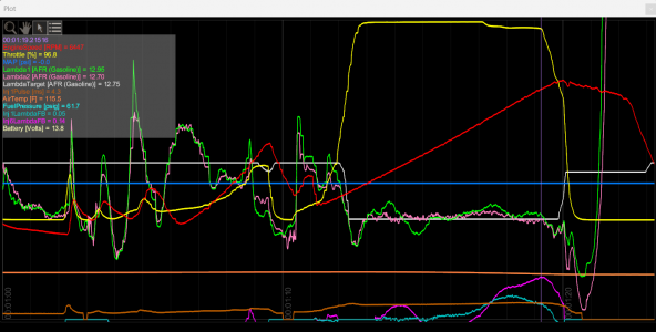
I need some clarification about the data log. First off, I see two pink / purple lines and they are rather similar. I assume the top pink line is Lambda 2 and the bottom pink-purple line is the fuel correction?
Yes, exactly. The pink is the front bank (Bank 2 - cyl 456)) AFR. I have no clue why it doesn't scale on top of the green line which is the rear bank (Bank 1) AFR. It's purely just the graphing and scaling. The actual AFR readings on the legend on the left is showing the correct numbers.

Yes, the fuchsia line is the amount of correction from the baseline tune Danny @ Unrivaled Tuning put in as a starting point.
What are the units for the LambdaFB? You seem to be assuming %; but, could it be a ms adder?
Yes, this is a % adder in the VE table. So the 0.14 number in Inj6LambdaFB is adding 14% more fuel in the front bank at that point in the map to achieve the 12.7 AFR.
0.14ms added to 4.3 ms would only be a 3.2% correction. It would be useful to display the injector pulse widths for both the front and rear banks. If your logging software auto scales see if you can change the scaling parameters so that
I'm use to pulse width tuning also with my HKS. Granted i'm a hack tuner so i'm sure I understand much less than I think I do. With that said, i'm not sure I found a injector pulse width data logging parameter. I'll have to ask Danny.
What is that fuel pressure measurement? Is there a scaling problem because 61.7 is well above the target of 40 psi.
We had tried 3 different baseline fuel pressure settings. 60psi was were we had left it at 9pm at night and called it quits. It's been at 60psi since the current tune is based on it. This is why i'm hesitant to put the stock FPR back in. I'd have to redo the base VE table tuning and introduce yet another moving target which I decided not to do right now. If I decide to buy a new FPR i'll have to set it as close to where it is at right now and I won't change it back to say 40psi (which is where I want to be) until the next dyno visit.
The AFRs measurements confuse me. During the wide open throttle run the target AFR is 12.75. During the run Lambda 2 is mind buggeringly well behaved, almost like it was painted on the screen at 12.7. If you are running open loop at wide open throttle and bank 2 is measuring 12.7 with a target of 12.75 you have essentially no O2 error. I would be incredibly happy if my open loop AFR remained so close to target. Or are you running closed loop? Lambda 1 is bouncing around a lot more during the wide open throttle run and is more like what I am used to seeing.
WOT is currently set to Closed Loop on both banks. Edit: See below.

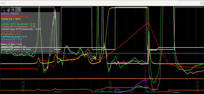
Here is a rescaled graph.
1690829666842.png
The Inj6LambdaFB values are moving around during the wide open throttle run which adds to my confusion for 2 reasons
- are you running open loop and Inj6LambdaFB is just the calculated correction; but, is not being applied? If so your AFR is so close to target I don't know why there is any calculated correction because Lambda2 AFR is pretty much on target
It's my understanding that the AFR is that "good" because of the correction applied. I'm not sure if this is truly the case though. It seems that the ECU can't be that good. This is where my lack of experience shows.
- are you running closed loop and Inj6LambdaFB is being applied to correct the AFR? If so, the Inj6LambdaFB value is moving around during the run. You need some error to generate a correction and normally I would expect to see some deviation in the AFR before the correction occurs. It may be a scaling problem; but, I don't see any errors in the AFR that would trigger that correction.
This is a good point. As mentioned above, i'm not 100% certain if the AFR is that good because of the applied Inj6FB correction.

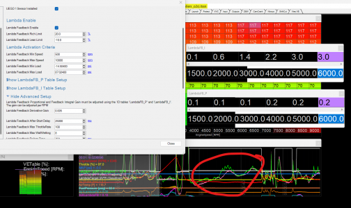
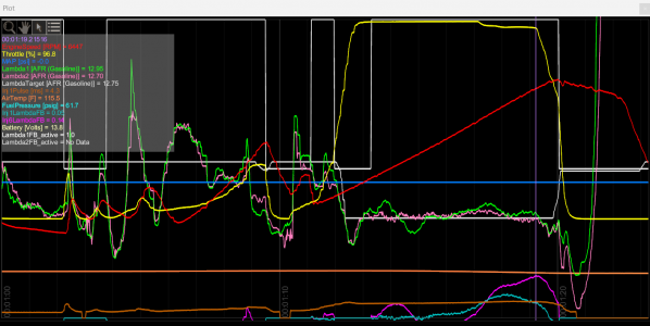
I noticed something interesting below. Since you asked me a good question if LambdaFB 1 vs 2 could be active or not. So I brought those into the graph. 0 = Inactive, 1 = Active. Bank 1 is Active but Bank 2 shows no data. I believe this is due to "Lambda2FB_active" was simply not setup to log during this run. I'll have to run this log again to be sure. I'm going to ask Danny about this now.
1690830200071.png

Great questions from you and @bogle. Thanks guys. It really helps.
 
I think it is good that you are no longer so hung up on the fuel pressure question. That is a good approach as long as the fuel pressure is on target at high load.
Yes, it's not a high priority at the moment. I think, even at VTEC i'll have enough injector to compensate. We shall see!
I need some clarification about the data log. First off, I see two pink / purple lines and they are rather similar. I assume the top pink line is Lambda 2 and the bottom pink-purple line is the fuel correction? What are the units for the LambdaFB? You seem to be assuming %; but, could it be a ms adder? 0.14ms added to 4.3 ms would only be a 3.2% correction. It would be useful to display the injector pulse widths for both the front and rear banks. If your logging software auto scales see if you can change the scaling parameters so that
I revised the scaling in the graphs below. This is a bit easier to read. I also added a log value for "Lambda1FB_active" and "Lambda2FB_active". I believe this shows when =0 then it's inactive and =1 is active (i.e. Closed Loop). The interesting thing is Lambda2FB_active" shows "No Data" as the value. I"m unsure if this because of A) it simply wasn't setup to log this metric or B) it actually is off or something else unusual. Clearly Bank two is adding up to 14% more fuel so it must be =1. I'm asking my tuner if he knows what's going on.

Yes, the 14% is the Closed Loop feedback adding 14% of fuel to the VE table for that part of the map.
Yes, the pink line is AFR and Fuchsia line is the correction factor. Well, that's my understanding at least.

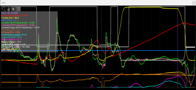
I have to look around to see if pulse width is an available metric. Because this is a VE tuning setup i'm not sure if it will show the injector pulse - it ought to. UPDATED: Added a 3rd graph showing injpulse width in MS.

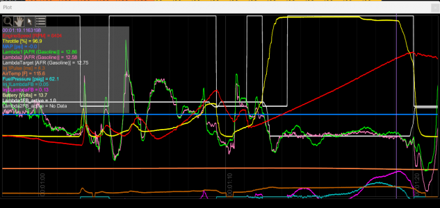
This is a 2nd gear pull
1690831164091.png

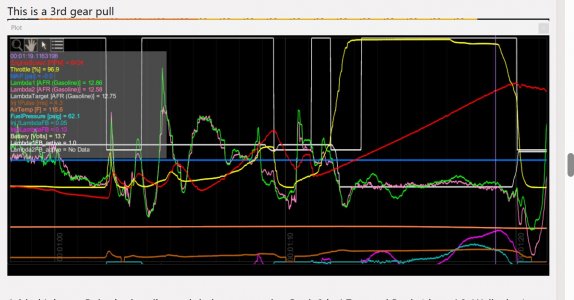
This is a 3rd gear pull
1690831198667.png

Added Injector Pulse in the olive and dark orange color. Bank 2 is 4.7ms and Bank 1 is at 4.3. Well.. that's really Injector 6 and Injector 1 but the correction factors are applied at the Wideband sensor level - we knew that! That's about a 9% difference... I wonder if that 9% added pulse width jives with the 14% more fuel.
1690831860440.png
What is that fuel pressure measurement? Is there a scaling problem because 61.7 is well above the target of 40 psi.
We left it at 60psi when I left the dyno at 9pm. We just ran out of time to set it back to 40psi and retune the VE table. So now i'm stuck with 60psi so I can keep it apples to apples while testing and not add yet another parameter of change.
The AFRs measurements confuse me. During the wide open throttle run the target AFR is 12.75. During the run Lambda 2 is mind buggeringly well behaved, almost like it was painted on the screen at 12.7. If you are running open loop at wide open throttle and bank 2 is measuring 12.7 with a target of 12.75 you have essentially no O2 error. I would be incredibly happy if my open loop AFR remained so close to target. Or are you running closed loop? Lambda 1 is bouncing around a lot more during the wide open throttle run and is more like what I am used to seeing.
I also wondered why Bank 2 AFR is so well behaved. However, it's my understanding that FB is ON or rather =1 (i.e. Closed Loop and hence affecting the AFR on-the-fly.
The Inj6LambdaFB values are moving around during the wide open throttle run which adds to my confusion for 2 reasons
- are you running open loop and Inj6LambdaFB is just the calculated correction; but, is not being applied? If so your AFR is so close to target I don't know why there is any calculated correction because Lambda2 AFR is pretty much on target
- are you running closed loop and Inj6LambdaFB is being applied to correct the AFR? If so, the Inj6LambdaFB value is moving around during the run. You need some error to generate a correction and normally I would expect to see some deviation in the AFR before the correction occurs. It may be a scaling problem; but, I don't see any errors in the AFR that would trigger that correction.
 
Running closed loop at wide open throttle is a bit of a design philosophy issue. It is something I don't do; but, that does not make it wrong, just something I am not used to.

In this 3rd gear log, the front and rear AFR values track each other remarkably closely - until you go wide open throttle.


3rd gear log.jpgThe fact that prior to going WOT the front and rear measured AFRs match so closely suggests to me that the front and rear O2 sensors and controllers are probably operating correctly - reporting the same AFR values. The front and rear AFRs stop tracking each other shortly after you hit wide open throttle - about the same time that that LambdaFB1 goes active - I don't know whether that is correlation or causation. I really don't know what is happening.

As a wild ass suggestion, your bank 1 fuel correction is smaller; but, bank 1 is having bigger excursions on the AFR than bank 2 during WOT. Does your ECU have separate front and rear adjustable control parameters for the exhaust gas correction loops (proportional and integral control settings)? Perhaps the front and back feedback loop control parameters for exhaust correction are set differently and the problem is that bank 1 is under correcting in terms of hitting AFR targets (bank 2 being pretty much on the money). If there is a problem with the bank 1 control parameters, maybe fixing that will correct the poor control performance on bank 1 AFR. If you get bank 1 AFR values to match bank 2 then you may find that both bank 1 and 2 fuel corrections assume the same (high) values. That could then point you in the direction that the problem is actually a 'low spot' in the fuel map that needs to be plumped up to reduce the correction on both banks.

Aside from not running exhaust correction at high engine load, I like to tune with the exhaust correction turned off during tuning (still recording the AFR; but, no corrective action). That way I know I am running directly off the fuel tables and not getting jerked around by O2 feedback. Depending on how much you trust your fuel map, you could switch off your fuel correction and do some incrementally increasing pulls measuring AFR. If the AFRs on the front and rear match; but, are not on target then you know that you have to tweak the map to get on target. If going back to closed loop then causes an unbalance you need to figure out what is going on with the fuel correction control algorithms. If the front and rear AFRs do not match with the fuel correction turned off, then you have a fundamental problem that could be your timing belt. But, your AFRs are so matchy - matchy at some loads that I do struggle with that particular scenario.

That kind of establishes the bounds on my out of the box thinking!
 
@Old Guy that's really quite a brilliant analysis. It did not occur to me to turn off the AFR feedback and see how the AFRs are tracking. So simple, it's brilliant. First principles which I didn't even consider because I was so caught up on what my tuner threw on my lap.

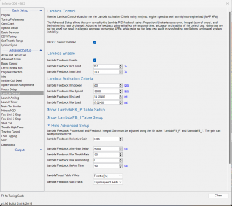
Based on my understanding (which I will confirm with Danny) there is no individual Lambda settings outside of the individual cylinder compensations. For example, in the screenshot below there's just one global toggle to turn on/off Lambda FB.

However, I do see the PID setting option for the Lambdas. I have to be honest though.. adjusting PIDs is something I never understood. I can barely play around with them on my IACV for idle control. I'm not comfortable messing with the stock settings of the AEM Widebands. Isn't this for when you're using another manufacturers controller/sensors? Anyway...

What I don't understand is your reference to "exhaust correction". Would you mind elaborating what that is?

BTW... Danny and I share the same methodology as you. We don't turn on AFR Feeback until the base table tune is done. We did it in this instance because the AEM Closed Loop appears to be fast enough to compensate and i'm using it for troubleshooting w/o blowing up my motor.

1690844209645.png
 
following your train of thought (I think...) I wonder if there's something wonky in my headers or muffler that's causing the rear bank to flow less exh gasses and hence adding more fuel to the front bank. I've already swapped out the cats so all that's left is the muffler and headers on the exhaust side.

Good point about the AFRs tracking near dead nuts to each other at low RPM. That's surprisingly hard to do at low to moderate idle because of the balancing of the ITB pushrods in the V configuration. I'm glad I got that part right. It's a long and meticulous process.
 
Easy thing first
What I don't understand is your reference to "exhaust correction". Would you mind elaborating what that is?
My unfortunate use of slang that I have picked up. Some references will use the term EGO correction which is short for Exhaust Gas O2 Correction - measuring the free O2 in the exhaust gas to determine lambda. So, its the signal being generated by your wideband.

However, I do see the PID setting option for the Lambdas. I have to be honest though.. adjusting PIDs is something I never understood. I can barely play around with them on my IACV for idle control. I'm not comfortable messing with the stock settings of the AEM Widebands. Isn't this for when you're using another manufacturers controller/sensors? Anyway...

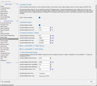
As you note, the Infinity controller does have provision for PID control. The firmware has to have some type of control algorithm. You can't just take the difference between measured and target AFR and apply it to the fuel PW. At the very least there has to be some scaling and conversion factors in the control loop to determine the change in PW. Parsing the wording in the Infinity Wizard, I expect that the Infinity uses a PID control algorithm because it says "The advanced settings allow the user to modify .. the gains". It may have default settings for P and I that are safe; but, it does allow you to fiddle with the D - derivative gain. That is fine if you don't want to fiddle with the P&I settings, I just suggest that you open the windows to make sure that both the front and back lambda control loops are using exactly the same settings. In particular that P & I did not get tweaked at some point on one of the loops and then get forgotten about. Its just a matter of checking to rule it out as a possible factor.

Based on my understanding (which I will confirm with Danny) there is no individual Lambda settings outside of the individual cylinder compensations. For example, in the screenshot below there's just one global toggle to turn on/off Lambda FB.

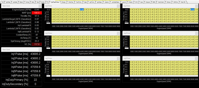
I don't understand this. What are the individual cylinder compensations? @bogle referred to fuel trims in post #23 and I don't remember you commenting. Does the Infinity have 6 individual fuel trim maps or front and rear trim maps or trim settings? If you have trim maps or single cylinder trim values are they zeroed out or populated with values? If you are using individual cylinder trim values I would review them to see if the trim values could be causing the requirement for additional fuel on the front.

If you are using trim values, I am curious as to how you set them. Did you have six exhaust gas thermocouples or a temporary 6 O2 sensor installation to measure individual cylinder mixtures. I went through a cylinder trimming exercise on my 4 cylinder using thermocouples. I started out with my base fuel map. Running open loop fuel control I adjusted the individual cylinder trims up and down so that all exhaust temperatures were the same. Of course, when you trim one or two cylinders this screws up the overall blended lambda value so you need to go back and adjust the fuel map to get your lambda back to target. Then you need to recheck the exhaust temperatures and maybe tweak them again and recheck your lambda values which can have you going around and around. Like the fuel map, the trim maps can have values that change as the engine operating conditions change so theoretically you need to do check this for every fuel cell. I think my fuel map is 140 or 160 cells. With 4 trim maps that makes for a total of 700 - 800 cells to populate. After a while, I decided that nobody way paying me to do this so I kind of quit and adopted a safe blended AFR target.

Final question. In post #26 you talked about including lambda active on the log display and I see that white line which I guess is toggling between 0 and 1??? Does that mean that the lambda correction is switching on and off. Looking at your activation criteria in the Infinity software I would guess that the lambda correction should always be active once you have completed the start delay. Is there some other control parameter.
 
I just checked and I can't find any individual wideband calibration factors. That's odd. There should be. I emailed AEM and hopefully they can help. You can see in my screenshot below that I sent them.. I see the I & D of the PID settings but it looks like a global change for both. Or perhaps this is just the internal onboard Wideband calibration.

1690919285590.png

This is what the per cylinder fuel compensation tables look like. Unfortunately this is a bit of a moot point because i'm not running individual Lambdas at each cylinder nor am I running individual EGT sensors. If I wanted to manipulate Bank 2 for example, it would be wise to make the same fuel trim adjustments to Cyl 4, 5, 6 simultaneously. The interesting thing about the AEM is it has an algorithm that can specify which cylinder is causing knock. I'm not sure I trust it but it's pretty cool as it measured knock two knock sensors but spliced into only one channel. Might be hocus pocus. I don't know.
1690919494890.png

On the LambdaTrimActive = 0 or 1 ----- It was showing "No Data" because Bank 2 was simply not logging at the time because the log parameter was turned on. The AEM doesn't log everything by default probably for obvious reasons.
 
AEM's Response - "Confirmation on how the infinity unit is reading is whether it reads/responds. There is no way to change how the input reads as it is designated to one sensor for the internal controller and one setting for the CAN (AEMNet) Input."

Basically I read as saying there is no individual controller configuration as they designed the external WB controller only for their own WB units.

What's EVEN MORE ODD... They suggested to try connecting the external wideband via the analog input, not via CAN BUS into the ECU. They claim CAN BUS is too fast and potentially noisy signal. I'm a bit shocked by that. My Spidey senses telling me that's not right.
 
All the trim tables appear to be completely populated with zeros, so that is not the cause of the apparent AFR skew from front to back - check that one off the list as done.

You have the screen shot for the UEGO 1 sensor. I assume that there must be another similar screen for the UEGO 2 sensor? I think the critical thing right now is that the values are the same for both sensors. It is possible that if you enable a second O2 sensor that it automatically assumes the same tuning parameters as UEGO 1; but, you need to confirm that with AEM. If it automatically assumes the same values for UEGO 1 and 2 then that automatically deletes different sensor set-ups as a cause. If not you need to find out where that data entry is for UEGO 2 and confirm that it matches the settings for UEGO1.

On the LambdaTrimActive = 0 or 1 ----- It was showing "No Data" because Bank 2 was simply not logging at the time because the log parameter was turned on. The AEM doesn't log everything by default probably for obvious reasons.

I understand the No Data. My question related to the fact that Lambda1FB Active appears to be toggling back and forth between 0 and 1 which I assume means that trim / correction is shutting off and turning back on. I don't understand that. It would be good to know whether something similar is happening for Lambda2FB Active and if so, why they are toggling back and forth. When I look at your activation criteria that says to me that the sensors should be active all the time... What does that toggling back and forth mean?
 
All the trim tables appear to be completely populated with zeros, so that is not the cause of the apparent AFR skew from front to back - check that one off the list as done.

You have the screen shot for the UEGO 1 sensor. I assume that there must be another similar screen for the UEGO 2 sensor? I think the critical thing right now is that the values are the same for both sensors. It is possible that if you enable a second O2 sensor that it automatically assumes the same tuning parameters as UEGO 1; but, you need to confirm that with AEM. If it automatically assumes the same values for UEGO 1 and 2 then that automatically deletes different sensor set-ups as a cause. If not you need to find out where that data entry is for UEGO 2 and confirm that it matches the settings for UEGO1.
Yes, I can confirm as per AEM that there is no user available configuration for their external UEGOs. Which made me wonder, do I have my internal configuration setup correctly. This is when AEM Support is hit or miss. Sometimes I'll get a guy who's super helpful. Sometimes i'll get a guy who's willing to share knowledge already in his brain but will refuse to the grunt work of looking up specific values for confirmation. AEM is a pretty shitty company all things considered in my experience.
I understand the No Data. My question related to the fact that Lambda1FB Active appears to be toggling back and forth between 0 and 1 which I assume means that trim / correction is shutting off and turning back on. I don't understand that. It would be good to know whether something similar is happening for Lambda2FB Active and if so, why they are toggling back and forth. When I look at your activation criteria that says to me that the sensors should be active all the time... What does that toggling back and forth mean?
I believe there is a 3D table (TPS vs RPM) that defines when Feedback is on or off for any given cell. I know i've seen it but can't recall what it was called so I can't find it. In my mind 0 = Open Loop and 1 = Closed Loop whereby feedback is essentially off at those parts of the map. I'll have to ask Danny what he's built in but knowing him he's probably gotten the lower parts of the VE table tuned well especially since my AFRs were consistent there. He likely turned on Feedback at the higher RPMs to compensate for the current oddities. I'll see him tomorrow and i'll verify.
 
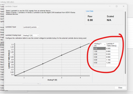
So it looks like I might be using a rudamentary analog wideband input method. Hope no one has F'ed with the voltage scaling here.
View attachment 182695
That is just the table for converting analog output voltage from an external wideband controller to the lambda / AFR value that the fuel control algorithm uses. That is pretty standard stuff if you are using an analog input for the wideband because wideband manufacturers do not all use the same slope on the response line. This allows you to set up your ECU so it correctly reads what the external wideband is outputting. The fact that your front and rear lambda values match most of the time suggests that the curve is probably correct; but, should be easy to check. Just find the install guide for you external wideband and it should tell you what the analog output voltage versus AFR values are.

The data in that screen shot suggests that you are using the analog input rather than CAN bus. I expect that the graph with input table would disappear or grey out if you selected CAN because there is no need to define those values. I don't think CAN versus Analog input has anything to do with your problems.

What's EVEN MORE ODD... They suggested to try connecting the external wideband via the analog input, not via CAN BUS into the ECU. They claim CAN BUS is too fast and potentially noisy signal. I'm a bit shocked by
that. My Spidey senses telling me that's not right.

That is a case of somebody throwing spaghetti at a wall to see what sticks. CAN bus can be a fast communication medium. The wideband controller is a device on the CAN network which is presumably repeatedly dumping AFR values onto the CAN network. The Infinity is presumably the master controller and gets to choose whether it wants to use those values or not. CAN is incredible fault tolerant and immune to noise - that is why it is the preferred network for mission critical data in nasty vehicle environments. This is all academic because you appear to be using an analog input for the 2nd wideband.

Yes, I can confirm as per AEM that there is no user available configuration for their external UEGOs. Which made me wonder, do I have my internal configuration setup correctly. This is when AEM Support is hit or miss.

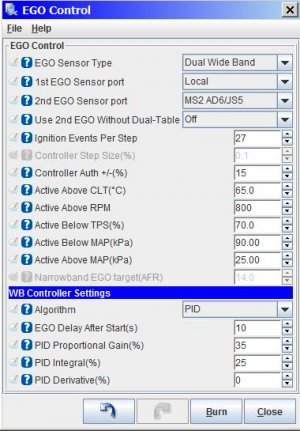
I opened up the configuration / tuning software for my ECU with my stored configuration file and then clicked on the drop down window for the O2 set up.
wideband setup.JPG

In the drop down window I changed the sensor type to dual wideband and it then un-greys the 2nd sensor input port allowing me to pick that. The wide band controller settings at the bottom does not add a second set of settings for the 2nd wideband because it is forcing the same settings for both wideband 1 and 2. In 99.999% of cases forcing the same control settings on both wide bands would be eminently sensible and is probably what the Infinity firmware is doing. It is just not clear from this window that the same settings are being applied because there is no reference to UEGO 2

1690991318568.png

The balance of probabilities probably sides on your problem not being caused by a difference in the wideband PID values. It would be sensible that the Infinity software is applying the above settings to both lambda control loops. It is just not clear that is what is happening. It would be nice to confirm that so that you can check off the box that box on the list of potential causes.

I believe there is a 3D table (TPS vs RPM) that defines when Feedback is on or off for any given cell. I know i've seen it but can't recall what it was called so I can't find it. In my mind 0 = Open Loop and 1 = Closed Loop whereby feedback is essentially off at those parts of the map. I'll have to ask Danny what he's built in but knowing him he's probably gotten the lower parts of the VE table tuned well especially since my AFRs were consistent there. He likely turned on Feedback at the higher RPMs to compensate for the current oddities. I'll see him tomorrow and i'll verify.

That would be good to do because I absolutely do not understand why there you would have two different sets of enabling criteria. That said, it would appear that wideband are probably not the cause of your front to back discrepancy.

I don't know how your ITBs are set up. Do you transition to pure alpha x N at higher engine output? If so, I only see one throttle position signal which jives with a single fuel map so I am guessing single TPS with mechanical linkage to the front and back ITBs? If so, is it possible that the linkage has come out of adjustment so that front throttle position is no longer accurate? Have you thought any more about a timing error causing the front - rear problem? I would expect that with your ITB set up you are going to have a really hard time getting a good idle manifold vacuum measurement with an analog gauge which may rule that out as an easy check. That may mean a more 'mechanical' inspection to confirm timing.
 
I had a long conversation with a local reputable shop and my tuner yesterday. These folks have become NSX exclusive shops lately. In their combined experience, they claim that in almost 100% of the cases the AEM pump turns out to be junk. My attempts at explaining that the fuel pressure drop is somewhat negligible and that the more pressing concern is Bank 2 lean condition fell on deaf ears {lol}.

I'm looking for a Walbro 450lph and it seems that will be on the list of To-Dos. I'm also going to clean the inside of the fuel tank. How to do that? I don't know. Could be as easy as just spraying it water and letting it dry upside down. I'll research this further.

I will also be measuring my vacuum. Despite the ITBs I have strong enough with the stock motor to fully power the brake booster. I do have the popular Volvo vacuum pump plumbed in case vacuum falls too much but I very rarely hear it come on.

I'm not looking forward to a mechanical inspection to confirm timing but I fear i'm just putting off the inevitable.
 
I can't comment on the AEM = junk statements. As an observation, according to Datanyze, AEM electronics has an employee count of 96. There is a separate company called AEM Induction which has 35 or 36 employees. If that is correct, I feel pretty confident that AEM Electronics fuel pumps are not manufactured by AEM Electronics employees. That is probably outsourced to some fuel pump specialist manufacturer and AEM may just be rebranding or dressing up some other pump. So, if you change the fuel pump just because somebody is bad mouthing the AEM label on the outside, you might unintentionally end up putting a pump from the same manufacturer back in the tank.

If you end up with fuel starvation issues then replace the pump if evidence indicates that it is the cause; however, right now I don't see any evidence of fuel starvation.
 
This has been one of the best technical threads on Prime in a long time! Dumb thought- have you considered using a R35 GT-R fuel pump? That thing is designed to deliver a lot more fuel than anything the NSX will ever need and still last 100,000 miles+.
 
I can't comment on the AEM = junk statements. As an observation, according to Datanyze, AEM electronics has an employee count of 96. There is a separate company called AEM Induction which has 35 or 36 employees. If that is correct, I feel pretty confident that AEM Electronics fuel pumps are not manufactured by AEM Electronics employees. That is probably outsourced to some fuel pump specialist manufacturer and AEM may just be rebranding or dressing up some other pump. So, if you change the fuel pump just because somebody is bad mouthing the AEM label on the outside, you might unintentionally end up putting a pump from the same manufacturer back in the tank.

If you end up with fuel starvation issues then replace the pump if evidence indicates that it is the cause; however, right now I don't see any evidence of fuel starvation.
yes, i don't disagree at all. Here's my viewpoint. It might be a bit political in nature. Asides from the amazing kindness and generosity of your time and knowledge from you and primates, I only have my local resources to fall back on in terms of this car. I'm getting mentally drained just from troubleshooting this fueling problem the past couple of years... ironically stems from my doing (LOL, I can just laugh at it now because I told myself I'd regret taking apart a bullet proof NSX that I built prior to this iteration).

I'm going to swap out this fuel pump to a Walbro 450lph. It appears to be the local favorite pump and I have it in-hand. There are a few things that nag me in the back of my mind with the last time I took it apart to put the AEM pump in. It was a bit of a rushed job if i'm honest. Mainly, I didn't flush the inside thoroughly and I didn't change any of the 30 yr old hoses attached to it. I just didn't have a restoration mindset the last time I pulled it out, but I do now. Therefore, I might as well do these things now. Can you tell i'm trying to justify pulling it out again?

After the new pump is in and I still have the same problem, maybe I'd get the buy-in from my local techs and we all can move forward towards other possible solutions together. At the moment, my local techs can't see past it being a fuel pump problem and at the end of the day, if i'm going to dump this problem onto someone (or I drive the car off a cliff) It will be the good folks at the shop.
 
This has been one of the best technical threads on Prime in a long time! Dumb thought- have you considered using a R35 GT-R fuel pump? That thing is designed to deliver a lot more fuel than anything the NSX will ever need and still last 100,000 miles+.
Ditto! An amazing thread. No, I have not! Darn.. you're like a day too late. I've got the Walbro 450lph in-hand. It seems to be universally loved in my local circle. Even though I had a horrible experience with a Walbro 255 which may have been fake.
 
Revisiting this list. I'll be tackling the items in green next as time permits.

What I might need to do next: :( :( :( :( :(
* Try Stock fuel pressure regulator or swap to new FPR
* Try new fuel pump and completely rebuild all fuel supply lines in -6AN
* Check fuel pump bypass or if pickup is too close to floor of tank.
* Cut open fuel filter and/or use aftermarket fuel filter

* Try larger fuel pump return line
* R&R the various gas tank purge valves and hoses
* Try larger fuel rail (long shot)
* Try to log with gas cap OFF - new gas cap installed
* Try new muffer and headers to verify flow of exhaust - done

* Compression check and Leak Down
* Swap spark plugs
* ???
 
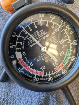
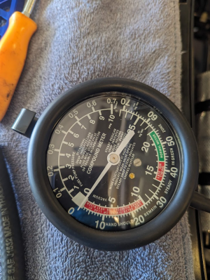
I went out to my 2000 to have a look at my fuel pressure regulator, or at least the little bit of it that you can see when everything else is in place. I thought the return line had threaded fittings. It doesn't. On my 2000 there is a 150 - 200 mm length of rubber hose between the discharge port on the FPR and the hard line that winds through the right side of the engine compartment back to the tank. The good news is that the rubber hose is connected to the hard line with a barbed fitting. This is good new because with a tee fitting and a short section of hose you can fit the tee in between the end of the flex line and the hard line. You can then run the tee to a 'good old days' fuel pump / vacuum gauge (typically measures up to about 10 psi). You do not want an EFI style pressure gauge because they are scaled to about 100 psi and are poor for reading low pressures. Start the engine up and take a measurement of the pressure on the FPR discharge port. Idle will have the highest return flow and the highest potential back pressure. In an ideal world the pressure would be close to 0 psi.

If the back pressure at idle is zero or negligible, then back pressure on the return line is not the cause of your fuel pressure weirdness and I have been blowing a lot of crap for the last 44 posts :(. If you measure back pressure at the FPR return port then you might have found the cause of your fuel pressure weirdness. I was looking at the OEM return line and it has lots of of moderately sharp bends in it which are conducive to creating back pressure if the return flow is high.

If you measure back pressure on the FPR return line I would be inclined to hold off on replacing with a larger / higher flow pump because that is just going to make the back pressure problem worse. I would also hold off on switching to the OEM FPR. It may also be sensitive to the back pressure associated with a high flow pump. If you still want to pursue the higher flow pump option, I would be inclined to chase the option of trying to up-size the return line before changing the pump.

I am still of the opinion that the front versus back cylinder bank fuel correction weirdness is unrelated to you fuel pressure weirdness. However, if you have to make the fuel pressure weirdness go away before your tuners can get their heads around the AFR weirdness then fix that first.
 
That's really interesting and fairly easy to do. I'm now super curious if it reads virtually near zero - its suppose to! The vacuum pressure gauge I just received today is compatible with gasoline up to 10psi. Perfect!

I was also able to measure the vacuum needle gauge behavior. I'm hoping, when convenient for @MotorMouth93, we can compare videos. He has a stock motor on my same ITBs.
 
 
I went out to my 2000 to have a look at my fuel pressure regulator, or at least the little bit of it that you can see when everything else is in place. I thought the return line had threaded fittings. It doesn't. On my 2000 there is a 150 - 200 mm length of rubber hose between the discharge port on the FPR and the hard line that winds through the right side of the engine compartment back to the tank. The good news is that the rubber hose is connected to the hard line with a barbed fitting. This is good new because with a tee fitting and a short section of hose you can fit the tee in between the end of the flex line and the hard line. You can then run the tee to a 'good old days' fuel pump / vacuum gauge (typically measures up to about 10 psi). You do not want an EFI style pressure gauge because they are scaled to about 100 psi and are poor for reading low pressures. Start the engine up and take a measurement of the pressure on the FPR discharge port. Idle will have the highest return flow and the highest potential back pressure. In an ideal world the pressure would be close to 0 psi.

If the back pressure at idle is zero or negligible, then back pressure on the return line is not the cause of your fuel pressure weirdness and I have been blowing a lot of crap for the last 44 posts :(. If you measure back pressure at the FPR return port then you might have found the cause of your fuel pressure weirdness. I was looking at the OEM return line and it has lots of of moderately sharp bends in it which are conducive to creating back pressure if the return flow is high.

If you measure back pressure on the FPR return line I would be inclined to hold off on replacing with a larger / higher flow pump because that is just going to make the back pressure problem worse. I would also hold off on switching to the OEM FPR. It may also be sensitive to the back pressure associated with a high flow pump. If you still want to pursue the higher flow pump option, I would be inclined to chase the option of trying to up-size the return line before changing the pump.

I am still of the opinion that the front versus back cylinder bank fuel correction weirdness is unrelated to you fuel pressure weirdness. However, if you have to make the fuel pressure weirdness go away before your tuners can get their heads around the AFR weirdness then fix that first.
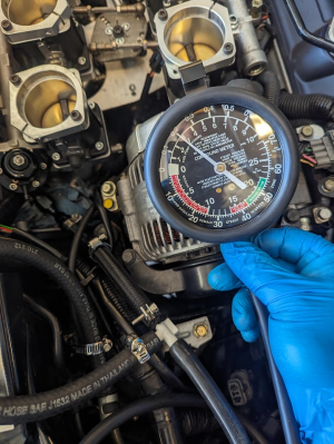
We're finally getting somewhere! I measured the return line backpressure as you suggested. No idea why that never occurred to me, but it's a brilliant suggestion.

At 60psi of fuel rail pressure it's 3psi of backpressure
1691262416671.png

At 40psi it's 4psi
1691262447208.png
Does that make sense that at higher rail pressure the backpressure is lower? It's a Saturday morning and i'm short a cup of coffee today. I suppose lower rail pressure could mean a higher return line output. Asides from the "too small" return line, could this be a FPR problem? I'm even wondering if this could be a problem with the fuel pump internal bypass.

At rest (ambient)
1691262486120.png
 
To add... (and to pad my nsxprime post count)

I tried my OEM FPR, granted it's 30yrs old. It had a rail pressure of 65psi with a ~3psi backpressure on the return line. I thought it was suppose to hold around 35-40psi and is pump independent. I'm unsure if these FPRs are relative to fuel pump flow rate - I suppose they are.

I then tried an old B series FPR I had lying around. It bolts right up. It was at 60psi with a similar backpressure.

Here's the interesting part. As I removed the return line on either FPR the lines would spit out A LOT of fuel. In other words, the hard line from the fuel tank is reversing the flow of fuel on it's on and causing gasoline to come out of the return line. This leads me to believe there is positive air pressure building up in the fuel tank, but HOW? I can also confirm that as I uncap the fuel filler cap. There's a clear sound of woooooooooooosh air the air rushes through. Unsure from this test if air is rushing in or out. This is merely from perhaps 5 mins of having the car hold idle.

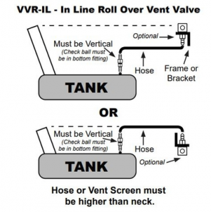
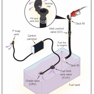
It seems like my fuel tank has a problem equalizing air pressure but which of those diaphragms is/are responsible for this?

I ran one more test. I kept the car idling but with the gas filler cap uncorked. The backpressure was the same so perhaps the tank is not pressurizing with air? Now i'm really confused.

I feel like i'm on a wild goose chase. Perhaps all of this simply normal behavior.

EDIT: At this rate... i'm planning on dropping the tank and building my own venting system which I really do not want to do.
1691266339272.png

1691266356658.png
 
Last edited:
Well at least I do not appear to have been blowing crap for the last 44 posts.

It is normal for you to get a slight woosh when you open the gas tank filler cap. It should not be huge. As noted earlier, I think the two way valve is supposed to burp to relieve tank pressure at about 0.6 psi (need to check the numbers in that prior post). So, hypothetically tank pressure should only be contributing a maximum of 0.6 psi to the back pressures that you are measuring. If you want to determine whether tank back pressure is causing / contributing to your return line pressure, run a length of rubber hose that is the same internal diameter and length as the OEM return line into a vented 5 jerry can. Throw a couple of tight loops into the line to simulate the OEM line bends. 5 gal should give you a couple of minutes of running time to check the back pressure with an idling engine. If the back pressure goes away, maybe the tank venting system is the problem. If the back pressure is still present perhaps the problem is a return line that is too small for the amount of flow. Your following test
I ran one more test. I kept the car idling but with the gas filler cap uncorked. The backpressure was the same so perhaps the tank is not pressurizing with air? Now i'm really confused.
did close to the same thing and suggests that the back pressure is due to restriction in the return line. You get a mungo fat hose and connect it to the regulator return port and dump that into the jerry can. My expectation is that should greatly reduce the back pressure.

You may need to do both the vacuum and pressure test on the two way valve to confirm that it is operating correctly.

Fuel pumps are primarily flow producing devices. They generate pressure because something is restricting the flow and as that restriction increases flow tends to drop off. A higher setting point on a regulator increases the restriction which tends to reduce the flow rate through the return line because the total pump flow is lower. These Walboro curves clearly show that as you increase the control pressure flow drops

Your numbers with the OEM regulator are definitely out of spec. The 1991 service manual (pg11-95) implies a base pressure of 50 psi. During test with the manifold pressure reference line disconnected the service manual states that 46 - 53 psi is acceptable. Regulators are pump independent to a limit. The regulator has to be physically sized to manage expected flows. If your pump has a flow rate that grossly exceeds the flow rate of the the OEM pump (particularly when the pump is operating at reduced voltage) the OEM FPR may not have the capacity to manage a lot of flow. When I went out to my car to look at the return line configuration I remember thinking that it is really small and may not be capable of handling high return line flows.

I am missing something with your evap system drawings. I don't see a purge line. No purge provision for the charcoal cannister and it is going to get loaded with hydrocarbons pretty quickly and become useless.
 
Back
Top