
Does the accord steering rack shaft need to be cut shorter?
-
***Text Box Error UPDATE*** Folks- we were able to fix the underlying issue with the missing text box on the forum. Everything should be back to normal. - Honcho
You are using an out of date browser. It may not display this or other websites correctly.
You should upgrade or use an alternative browser.
You should upgrade or use an alternative browser.
S2k rack on NA1
- Thread starter nsxmugen
- Start date
- Joined
- 30 December 2002
- Messages
- 232
Does the accord steering rack shaft need to be cut shorter?
No it does not. The only modification to Accord rack that is needed is to cut the mounting brackets. The steering shaft/tq sensor does not need to be removed/modified on accord rack. My custom crossmember that holds the steering rack has the correct dimensions to just couple it with steering wheel shaft. Everything is fully reversible. It took many attempts and try and error to get it right. There is about .5" room for error in each direction.
I think there reason the shaft is longer on S2000 is because it's almost in front of the engine in S2000, then you have several feet of steering rod between the driver and steering rack. Some skilled S2000 drivers notice the flex in the shaft and there are mixed reviews in S2000 community about it's steering. But this is not the case when utilizing S2000 rack on nsx, because it's directly bolted on to steering wheel rod.
Last edited:
- Joined
- 30 December 2002
- Messages
- 232
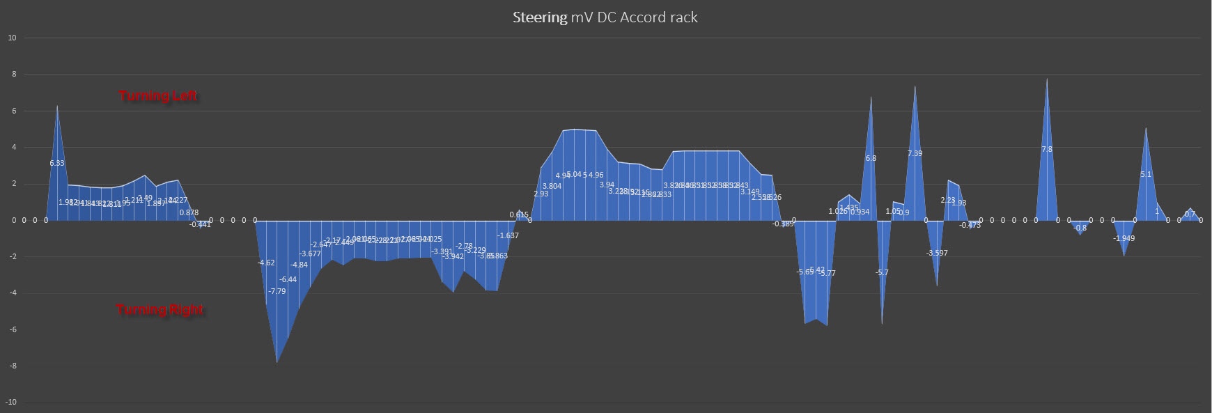
I forgot to update that I’m looking in to controlling the assistance. I’m hoping to fab a power adjust selector to take out 20-40% on demand so it would provide more customization but this will be some. I don’t know much about voltage reduction but I logged it with 3 samples a second and turning right will generate negative volt and turning left positive. Now just to build a switch some how to reduce assistance or have two or three modes to select from.
Sent from my iPhone using Tapatalk Pro
Sent from my iPhone using Tapatalk Pro
- Joined
- 30 December 2002
- Messages
- 232
Hi, OP, do you have the length on the S2k rack from inner to inner? Looking to do this swap on another car but want to make sure it's close in length to mine before purchasing.
Thank you!
It’s 32” from inner to inner
Sent from my iPhone using Tapatalk Pro


I forgot to update that I’m looking in to controlling the assistance. I’m hoping to fab a power adjust selector to take out 20-40% on demand so it would provide more customization but this will be some. I don’t know much about voltage reduction but I logged it with 3 samples a second and turning right will generate negative volt and turning left positive. Now just to build a switch some how to reduce assistance or have two or three modes to select from.
Sent from my iPhone using Tapatalk Pro
I am guessing that the voltage plot above is the voltage applied directly at the EPS drive motor terminals? The voltage reversal produces the change in torque direction required to apply assistance when turning left or right. The adjustable and reversible voltage is likely obtained by using FETs doing pulse width modulation to adjust the magnitude and an H bridge configuration to provide the polarity reversal.
I don't think that tweaking the controller output voltage to reduce the torque that the drive motor provides (which is what we feel as assist) is going to be effective at reducing the assist level. The EPS gets its control signal from the torque sensor on the input steering shaft. In the torque sensor there are two rings on the steering shaft connected together by a semi flexible element. When you apply torque to the steering wheel steering input) that flexible element twists slightly which causes differential movement in the two rings. The controller senses that twist and then applies torque through the EPS motor to keep that twist to a set level (minimizes the amount of torque you need to apply to the steering wheel). I will speculate that the controller probably has a map of vehicle speed, perhaps steering angle and probably some other stuff versus a torque output. When the controller measures shaft twist on the input shaft it applies voltage to create 'assistance torque' which reduces the sensor shaft twist. I will speculate that for a given speed and other set of conditions the controller has a target steering shaft twist. If you try to tweak / reduce the controller output voltage this will initially reduce the assistance torque; but, the sensor will be telling the controller that it is not meeting the target twist value and the controller will just jack up the output voltage to take care of that perceived problem. In control theory speak, the controlled variable is the shaft twist not the output voltage to the EPS drive motor.
I think that there are potentially two ways to get adjustable assistance. Technically, the best way with the greatest flexibility would be to remap the control torque map in the controller. This is serious work, equivalent to what SR5guy did in characterizing the pre OBDII ECUs. Of course, more flexibility does bring the risk that you could really screw up the control strategy.
If the EPS accepts a pulse rate based speed signal, the simpler way would be to modify the speed signal pulse rate to trick the EPS controller into thinking the car is going faster than it actually is. Presumably assistance drops as speed increases so the option might be to install a separate interposing controller which picks up the actual vehicle speed signal and then adjusts it to create a signal showing higher vehicle speed than actual if you are looking for reduced assist. If your EPS accepts a vehicle speed signal that is a pulse rate this would be fairly easy to do in a separate microcontroller. You could create a table or an equation that says if this is my input speed (pulse rate) this is the output speed (pulse rate ) that I want to send to the EPS and then you could tweak that table / equation to reduce the assistance.
I am currently retrofitting a column style EPS unit to an older car. The column unit is from a Nissan. This unit uses CAN bus to communicate and gets the vehicle speed signal from the ECU via the CAN. In this case, there is no faking a pulse rate to fake a vehicle speed. However, I think you have the potential that once you have figured out the memory address for vehicle speed you can broadcast a 'faked' vehicle speed on the CAN if you want to reduce the assistance. I haven't investigated this yet because the controller I am using has a failure mode that if it completely loses the CAN bus it defaults to a minimum assist mode. Right now that minimum assist looks like it may be all I want to help with parking manoeuvers on this car. If it turns out that I want more assistance or want to completely turn off assistance at high speed I may have to chase the vehicle speed over CAN in the future.
Honda was late to implement CAN. Depending on the vintage of your Accord rack it may not have CAN and may just rely on a VSS signal out of the ECU.
Hey Guys!
Guinea pig #1 here. Finally got the rack installed in my 91' and have some initial impressions after driving around town and what not. It's feels pretty good imo. The car has a darty immediate response feeling. Slow speeds/turns the steering is almost tooooo light. But on cloverleafs and medium speed turns you have some steering resistance. But most importantly its alot easier to catch slides. :biggrin:
I'll plan to get it on track and do some autocross to see if the feedback of the rack is still present in some form or fashion and do some testing. Overall i recommend it. Many thanks to the OP!
Track testing update!
I was able to get on track for some light testing. My track impressions are the steering ratio is greatly improved, especially in tight corners. The precision and power assist from the s2000 rack is as expected, there is some feel and feedback. I'm not sure how much of the feedback from the nsx rack will carry over. i wasn't able to push it hard to see. I'm sure the track conditions (95 degrees) alignment (factory ish 2.2/2.4 camber f/r and .02/.05 toe f/r), garbage tires (federal 595rsrr 200tw 215/265 and garbage driver are all variables to gauge how much feel there is. I'd need a professional driver to test it out. :wink:
Anyway, here's a rough idea on the steering ratio differences atone of tightest parts of this track. all cars have 350mm steering wheels.
Left to right. is 97', 91', and 91' with s2000 rack. great improvement


.jpg")
This turn is least tight of the track. and not much of an change.
.jpg")


Lap with s2000 rack
https://www.youtube.com/watch?v=qlH_hcmAups
Some forced sliding to gauge recovery
https://www.youtube.com/watch?v=VRYoGKFZ5mY
Reference videos
https://youtu.be/V0XMjy1PlQo
https://www.youtube.com/watch?v=9swYWadwRWM
Next up is fixing my igntion/fuel cut off on left handers. More testing track testing and some autocross....ughhh.
I was able to get on track for some light testing. My track impressions are the steering ratio is greatly improved, especially in tight corners. The precision and power assist from the s2000 rack is as expected, there is some feel and feedback. I'm not sure how much of the feedback from the nsx rack will carry over. i wasn't able to push it hard to see. I'm sure the track conditions (95 degrees) alignment (factory ish 2.2/2.4 camber f/r and .02/.05 toe f/r), garbage tires (federal 595rsrr 200tw 215/265 and garbage driver are all variables to gauge how much feel there is. I'd need a professional driver to test it out. :wink:
Anyway, here's a rough idea on the steering ratio differences atone of tightest parts of this track. all cars have 350mm steering wheels.
Left to right. is 97', 91', and 91' with s2000 rack. great improvement
This turn is least tight of the track. and not much of an change.
Lap with s2000 rack
https://www.youtube.com/watch?v=qlH_hcmAups
Some forced sliding to gauge recovery
https://www.youtube.com/watch?v=VRYoGKFZ5mY
Reference videos
https://youtu.be/V0XMjy1PlQo
https://www.youtube.com/watch?v=9swYWadwRWM
Next up is fixing my igntion/fuel cut off on left handers. More testing track testing and some autocross....ughhh.
Last edited:
This is so amazing, I wish you would make conversion kits for us haha. Or maybe you're willing to share all the dimensions from your bracket so we can make them ourselves ") Seems to be a great update for our cars...
Seems to be a great update for our cars...
Seems to be a great update for our cars...- Joined
- 30 December 2002
- Messages
- 232
Videos looks awesome
I'm glad that someone else other then me got to try it. You motivate me to find out how can I get on the local track that we have here in Poconos PA. It's so close but I only been there as a visitor. This looks like a lot of fun
**update on the assistance level**
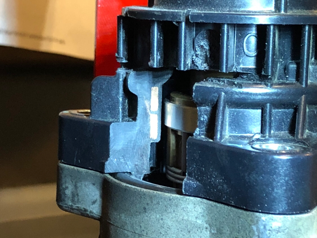
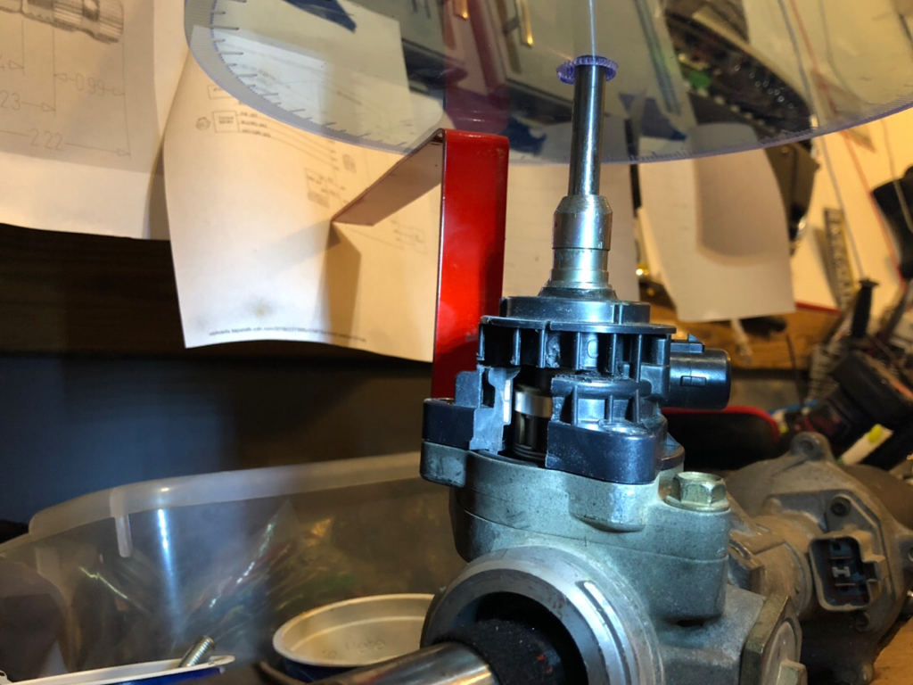
In the last couple of weeks I was busy on researching how the measurements are read from the tq sensor. There is ton of miss leading information specially of S2000 forums on S2000 rack. Only way to find out how it works was to brake one rack in to peaces and see how it all interact together. I want to share what I found so others would know as I could not find any solid information on it even from honda mechanics as tq sensor by honda is not serviceable part and nobody ever took one a part. "Old Guy" has a point regarding modifying the signal to the motor. This made me think and possibly closed my idea on making accord rack power assistance less over powered. But wait... the answer was simpler then I thought but I want to explain how the system works.
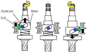
Below is picture of the shaft and how it works. The inner shaft is actually a torsion bar so when you turn wheels for example left the resistance from tires will cause the torsion bar to twist moving the slider up on to the upper coil, turning right would do the op-positive twisting torsion bar and moving slider down instead. Sensor coils are read based on the position of the slider and the farther the slider is the more assistance is given until the outer shaft reaches it's limit.
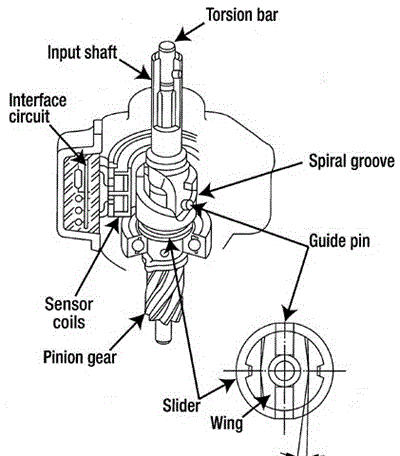
Here is a picture of the tq sensor cut open to get a view how it looks inside. The two gold bars are the coils and the aluminum ring on the inside is on the slider that moves up and down. Very simple system but works well.
This is what I found interesting. In Honda service manual procedure to reset to neutral position on the steering wheel it does not mentions anywhere that it reads the shaft torsion bar resistance vs tires. The procedure is with SCS cable grounded and with car turned off and ignition turned on. In the process the user needs to hold steering wheel at 45degree for 4seconds this forces the torsion bar to twist under resistance from tires and slider to go down at it's maximum. The vol is read twice and averages are calculated and written to EPS module. So to get more assistance the steering wheel needs to be forced less during the reset to neutral procedure, and to get less steering wheel assistance do the op-positive. This calibration is not explained in details anywhere, and only reason I found this is that I took logs of volts with two different calibration done on S2000 rack then I exported to excel to see graph and I seen difference of around .4volt it's not much but I was able to notice it on steering wheel. I think honda build in tolerances for this procedure to smooth out any discrepancy between turning left or right assistance. I did not try reset procedure on accord rack since it worked right a way. But I'm thinking since accord have different tires this procedure is a must to do when I get it installed again. I'm fine with accord rack as is but want to have clarity on this. This would be electronic way of modifying the assistance level, the physical way would be to mill new torsion bar that is thicker but this would be too involved.
Thanks,
David
I'm glad that someone else other then me got to try it. You motivate me to find out how can I get on the local track that we have here in Poconos PA. It's so close but I only been there as a visitor. This looks like a lot of fun
**update on the assistance level**
In the last couple of weeks I was busy on researching how the measurements are read from the tq sensor. There is ton of miss leading information specially of S2000 forums on S2000 rack. Only way to find out how it works was to brake one rack in to peaces and see how it all interact together. I want to share what I found so others would know as I could not find any solid information on it even from honda mechanics as tq sensor by honda is not serviceable part and nobody ever took one a part. "Old Guy" has a point regarding modifying the signal to the motor. This made me think and possibly closed my idea on making accord rack power assistance less over powered. But wait... the answer was simpler then I thought but I want to explain how the system works.
Below is picture of the shaft and how it works. The inner shaft is actually a torsion bar so when you turn wheels for example left the resistance from tires will cause the torsion bar to twist moving the slider up on to the upper coil, turning right would do the op-positive twisting torsion bar and moving slider down instead. Sensor coils are read based on the position of the slider and the farther the slider is the more assistance is given until the outer shaft reaches it's limit.
Here is a picture of the tq sensor cut open to get a view how it looks inside. The two gold bars are the coils and the aluminum ring on the inside is on the slider that moves up and down. Very simple system but works well.
This is what I found interesting. In Honda service manual procedure to reset to neutral position on the steering wheel it does not mentions anywhere that it reads the shaft torsion bar resistance vs tires. The procedure is with SCS cable grounded and with car turned off and ignition turned on. In the process the user needs to hold steering wheel at 45degree for 4seconds this forces the torsion bar to twist under resistance from tires and slider to go down at it's maximum. The vol is read twice and averages are calculated and written to EPS module. So to get more assistance the steering wheel needs to be forced less during the reset to neutral procedure, and to get less steering wheel assistance do the op-positive. This calibration is not explained in details anywhere, and only reason I found this is that I took logs of volts with two different calibration done on S2000 rack then I exported to excel to see graph and I seen difference of around .4volt it's not much but I was able to notice it on steering wheel. I think honda build in tolerances for this procedure to smooth out any discrepancy between turning left or right assistance. I did not try reset procedure on accord rack since it worked right a way. But I'm thinking since accord have different tires this procedure is a must to do when I get it installed again. I'm fine with accord rack as is but want to have clarity on this. This would be electronic way of modifying the assistance level, the physical way would be to mill new torsion bar that is thicker but this would be too involved.
Thanks,
David
Last edited:
- Joined
- 30 December 2002
- Messages
- 232
This is so amazing, I wish you would make conversion kits for us haha. Or maybe you're willing to share all the dimensions from your bracket so we can make them ourselves
Hi, yes I make a conversion kit. It's almost plug and play and fully reversible. If anyone is interested please PM me for details. I spend a lot of try and error on this and wound up created my own jig to calibrate the torsion bar to get it right.
Thanks,
David
**update on the assistance level**
In the last couple of weeks I was busy on researching how the measurements are read from the tq sensor. There is ton of miss leading information specially of S2000 forums on S2000 rack. Only way to find out how it works was to brake one rack in to peaces and see how it all interact together. I want to share what I found so others would know as I could not find any solid information on it even from honda mechanics as tq sensor by honda is not serviceable part and nobody ever took one a part.
Its the internet which everybody knows is the source of all truth! I once relied on internet wisdom for flow rates on some vintage (1970) Bosch fuel injectors when I was doing an EFI retrofit on a 'classic' car. Internet wisdom said 36 lbs/hr and I used this value to set up the initial parameters in the EFI. Car was near impossible to get started and required massive amounts of O2 correction and ended up with the weirdest looking fuel map in the world after I did some initial tuning. I finally decided 'that's stupid' and set up to do some actual flow testing on the injectors. Turns out the injectors were around 55 lbs/hr which explained a whole lot of problems. I applaud your excellent efforts around trying to take some real measurements to verify the operation of the EPS.
I need to make a correction to my July 9th post. In particular my assertion that the torque sensor consists of two ring arrangements coupled by a flexible / torsion
element. This comment was based upon my direct experience with the EPAS retrofit that I am doing on another car which uses a torque sensor similar to that described here:
https://exxotest.com/wp-content/uploads/2018/03/GU_MT-DAE_EN.pdf
Clearly your dissection indicates that this is not the type of torque sensor being used.
I linked that .pdf, not because it is directly applicable; but, because you may find the overview of the control strategy of some help in figuring things out and giving you some ideas for further testing. In particular, look at page 8 which shows the torque sensor output signal versus sensor torque. The slope of that line is going to determine the amount of torque assist that the controller and drive motor applies. Unfortunately, the 0 torque point for the line is about 2.6 volts. If the 0 torque output of the sensor had been 0 volts with negative torque giving negative voltages and positive torque giving positive voltages, it would have been mind buggeringly easy to alter the signal to the controller. A simple resistive voltage divider on the output of the torque sensor would have provided a nice linear reduction in the signal. Unfortunately the 0 torque point is at 2.6 volts. A simple voltage divider on the torque sensor output will reduce the response; but, in a very bad manner - the assist will vary depending on the direction in which you steer. However, there are Op Amp circuits that will allow you to alter the slope of that straight line and keep the zero torque point at 2.6 volts. Save this thought, although I would caution that practical Op Amp design can be tricky and they don't always play nice (personal experience).
Your dissection of the torque sensor indicates that it appears to be almost identical to the torque sensor used in the NSX EPS system. If that is correct, the system is more complex than the sensor and system described in that .pdf I linked. According to page 17-18 of the 1997 service manual, the torque sensor on the NSX has three output signals; TRQ1, TRQ2 and TRQ3. TRQ1 is the output from the upper coil (steer right), TRQ2 is the output from the lower coil (steer left) and TRQ3 is a signal 'based' upon the difference between TRQ1 and TRQ2. On page 17-34 of the service manual it provides the expected voltage ranges on these three signals. TRQ1 varies from 2.6 volts to 3 volts as you steer from left to right and TRQ2 has the reverse characteristic. TRQ3 has a characteristic that varies from 0 volts (fully left) to 5 volts fully right with neutral (0 torque) at 2.5 volts. That looks remarkably like a response line that is about the same as the response line described on page 8 of that .pdf I llnked and if so, that might be the actual signal that the controller is using to determine the amount of assist. If that is the case, you have the potential to modify the assist by scaling the torque sensor output by using an Op Amp based circuit. The big unknown in my suggestion is what the hell is the controller doing with the TRQ1 and TRQ2 signals. Can you scale the TRQ3 signal and leave the TRQ1 and TRQ2 signals alone or will that trigger some kind of error? If you want to chase this, an area of investigation might be to confirm the TRQ1-3 signals and then use an Op Amp circuit to scale TRQ3 (I think I still have some Motorola application notes on doing this) and see if the controller still accepts the signal or generates errors because of a discrepancy between what it is expecting on TRQ1 & 2 and what it is getting on TRQ3.
Holy crap I want to try this!!!

i'm sure that could be arranged")
Drive up to Laguna Seca this Saturday!!
- Joined
- 4 May 2008
- Messages
- 538
i'm sure that could be arranged
Make a youtube video about the kit on your channel.
Holy crap I want to try this!!!
You're more than welcome to drive it. :smile:
i'm sure that could be arranged
lol. shhh you!
You're more than welcome to drive it. :smile:
lol. shhh you!
Exactly! He's driving yours! Haha
Exactly! He's driving yours! Haha
Mine is too ratty. He should drive yours for all those youtube views and exposure Mr. Celebrity.
Mine is too ratty. He should drive yours for all those youtube views and exposure Mr. Celebrity.
I have no idea what you're talking about. I'm just here for the popcorn! :biggrin:
the manual rack is just too heavy for tight corners. my arms get very tired after a day.
This is awesome and thanks for sharing it with us! Just curious, how many hours would it take the average person to install your steering rack solution with the Accord rack?
- Joined
- 30 December 2002
- Messages
- 232
This is awesome and thanks for sharing it with us! Just curious, how many hours would it take the average person to install your steering rack solution with the Accord rack?
It takes me about 2hour to remove it and install it but I did it at list 30 times lol. It’s all accessible just need to have impact driver and tie rod puller. Other wise it could turn in to a day project.
It's interesting that the cluster on NA2 has different pin out then NA1. They both look the same but the pin for VSS and RPM are different. In case someone needs to know, here it is below.
VSS is pin 24 on connector C437 YEL/RED wire on NSX cluster (pin 22 orange on nsx with EPS or NA2)
RPM is pin 4 on connector C412 GRN wire on NSX cluster (pin 28 on nsx with EPS or NA2)
Attachments

Last edited:
- Joined
- 1 July 2011
- Messages
- 219
Well guys, I ended up buying one of the racks & kit -- specifically the Accord rack. I haven't had a chance to get it up to speed on the road, just waiting on some other parts, just went for a quick test drive.
I'll say the bit that I did experience was overall good. The steering did feel a little more "floaty", but nothing I wasn't expecting.
As I put it through it's paces on the street, I'll keep you guys updated.
I'll say the bit that I did experience was overall good. The steering did feel a little more "floaty", but nothing I wasn't expecting.
As I put it through it's paces on the street, I'll keep you guys updated.
I did a video on it because it became too much to write my thoughts on it.
https://youtu.be/qcpDs-0Ef4s
https://youtu.be/qcpDs-0Ef4s
Similar threads
- Replies
- 15
- Views
- 376