• Protip: Profile posts are public! Use Conversations to message other members privately. Everyone can see the content of a profile post.

***STICKY*** - Timing Belt & Transmission Rebuild Thread (2005 NSX 6MT)

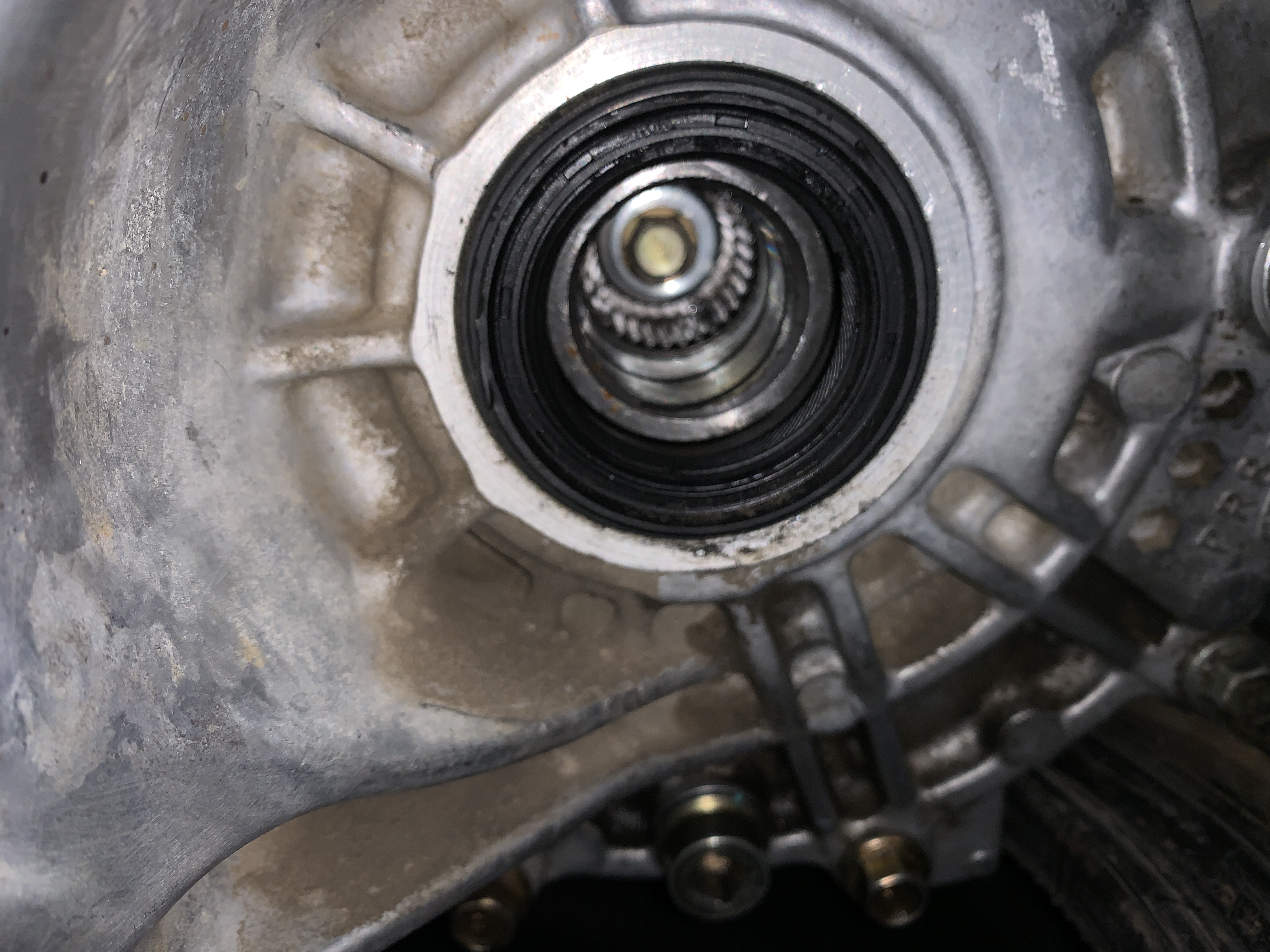
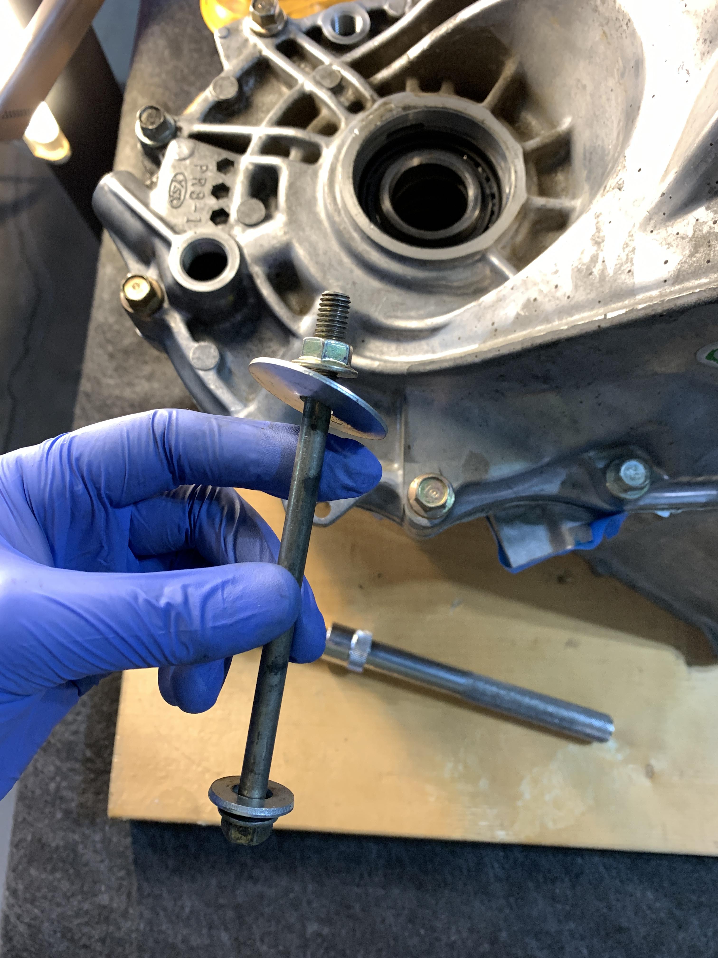
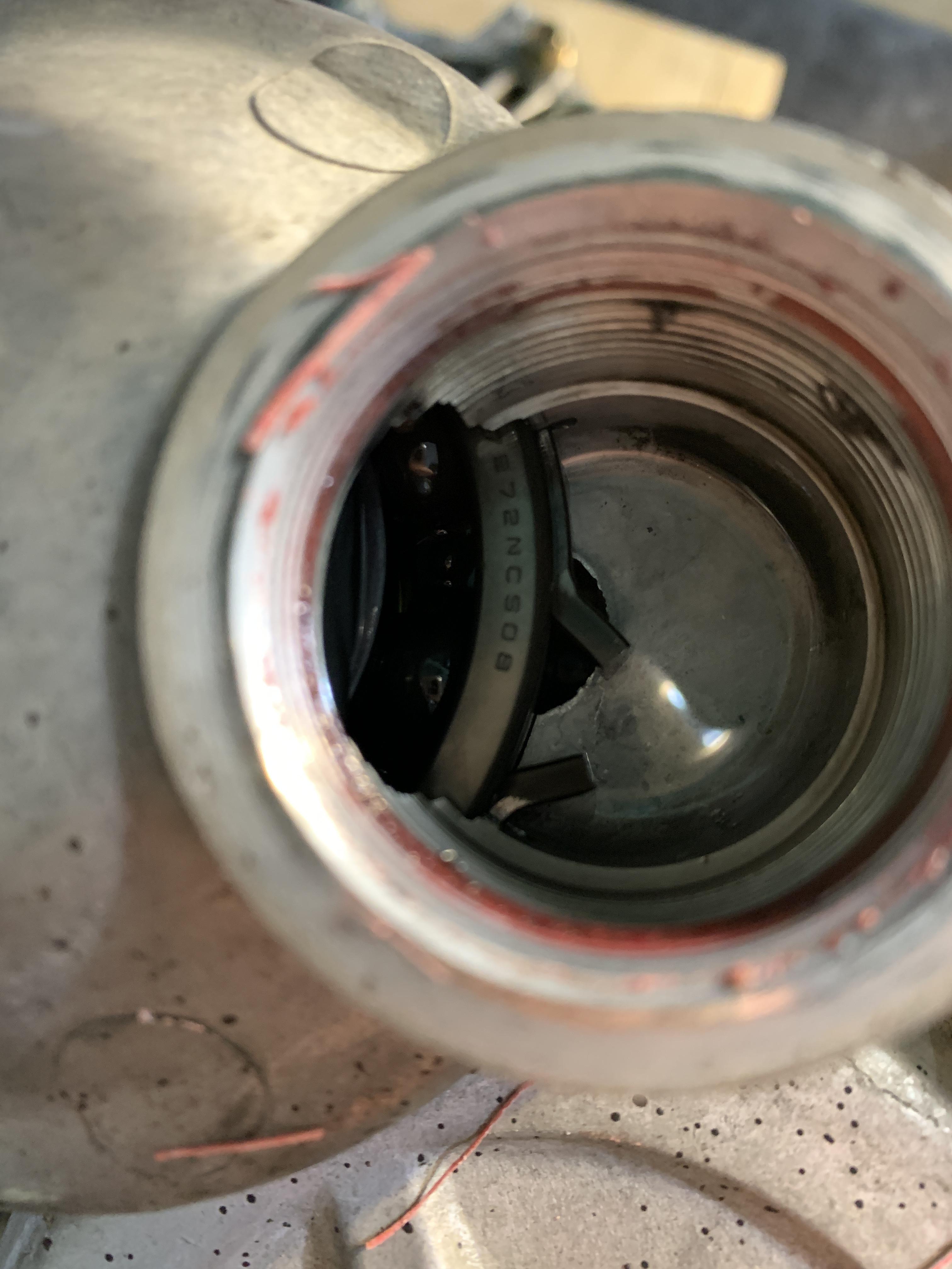
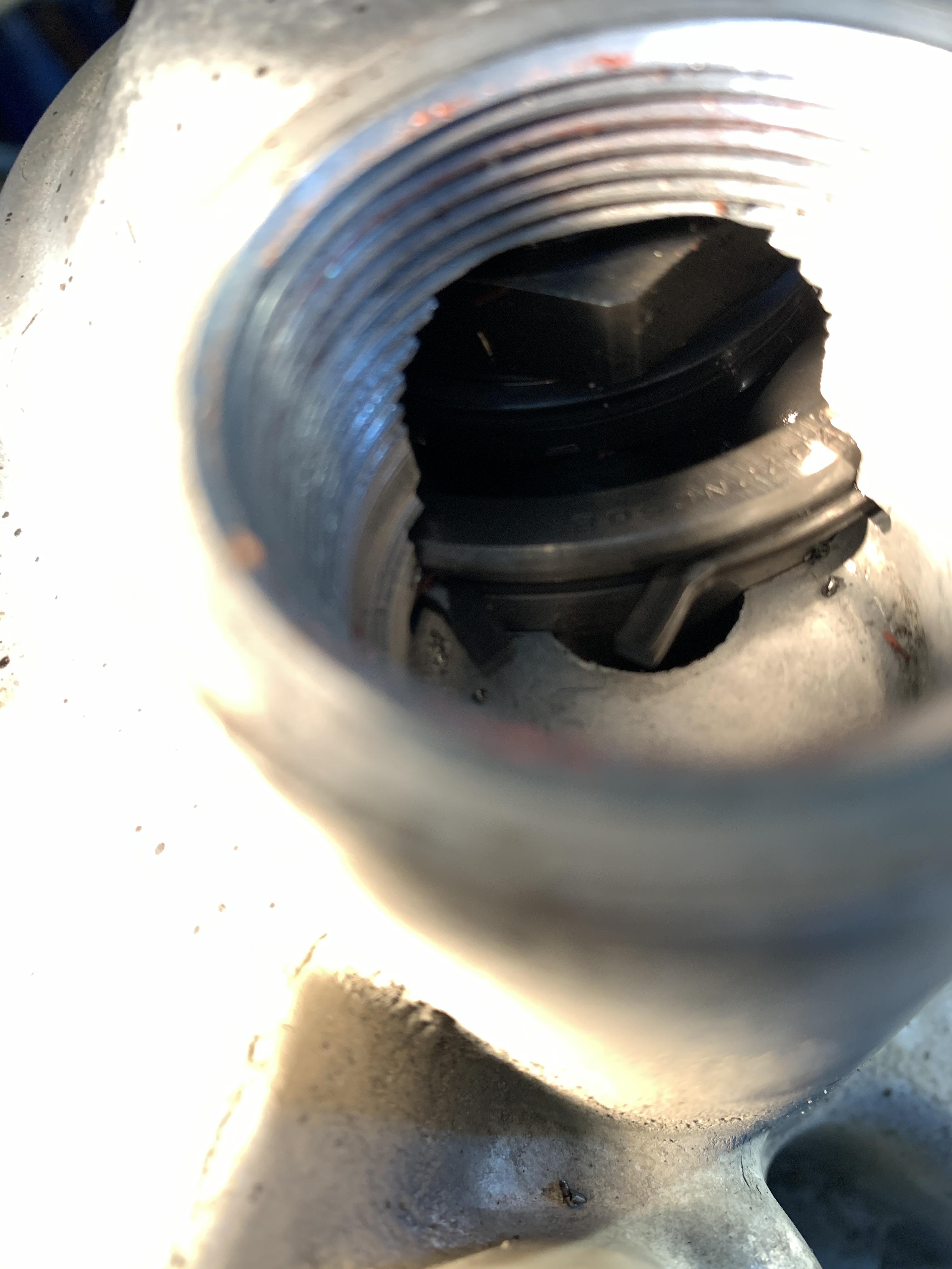
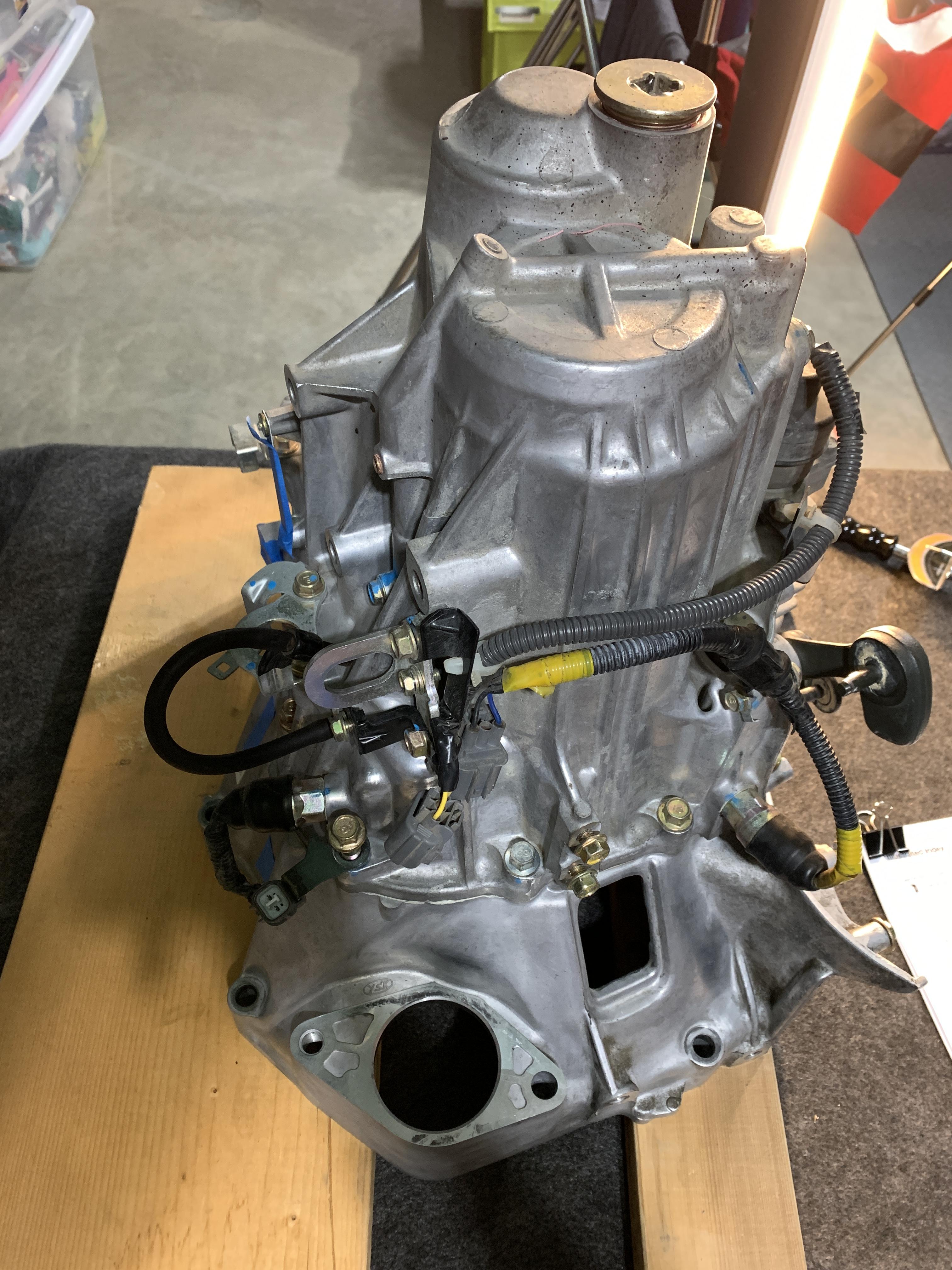
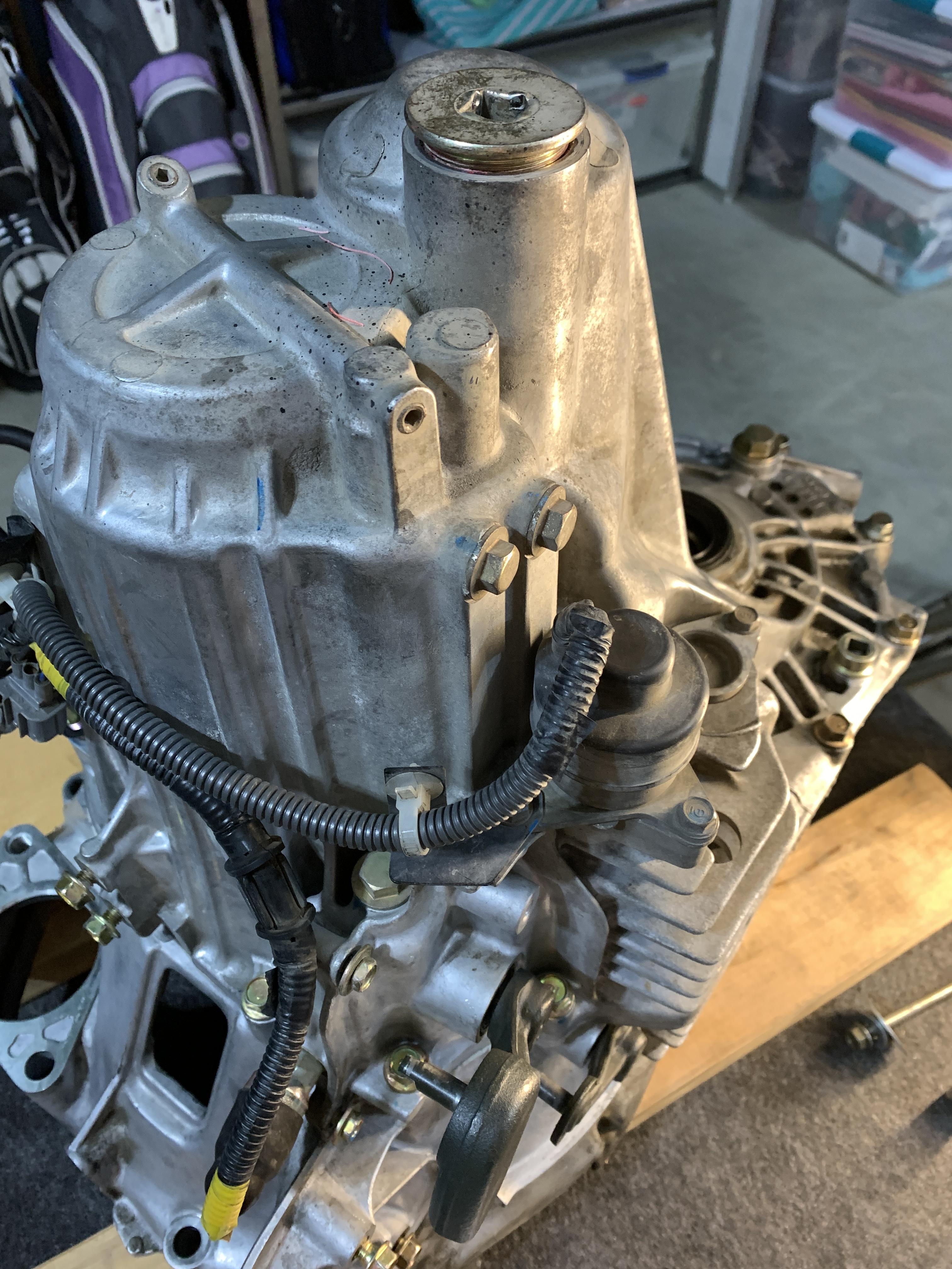
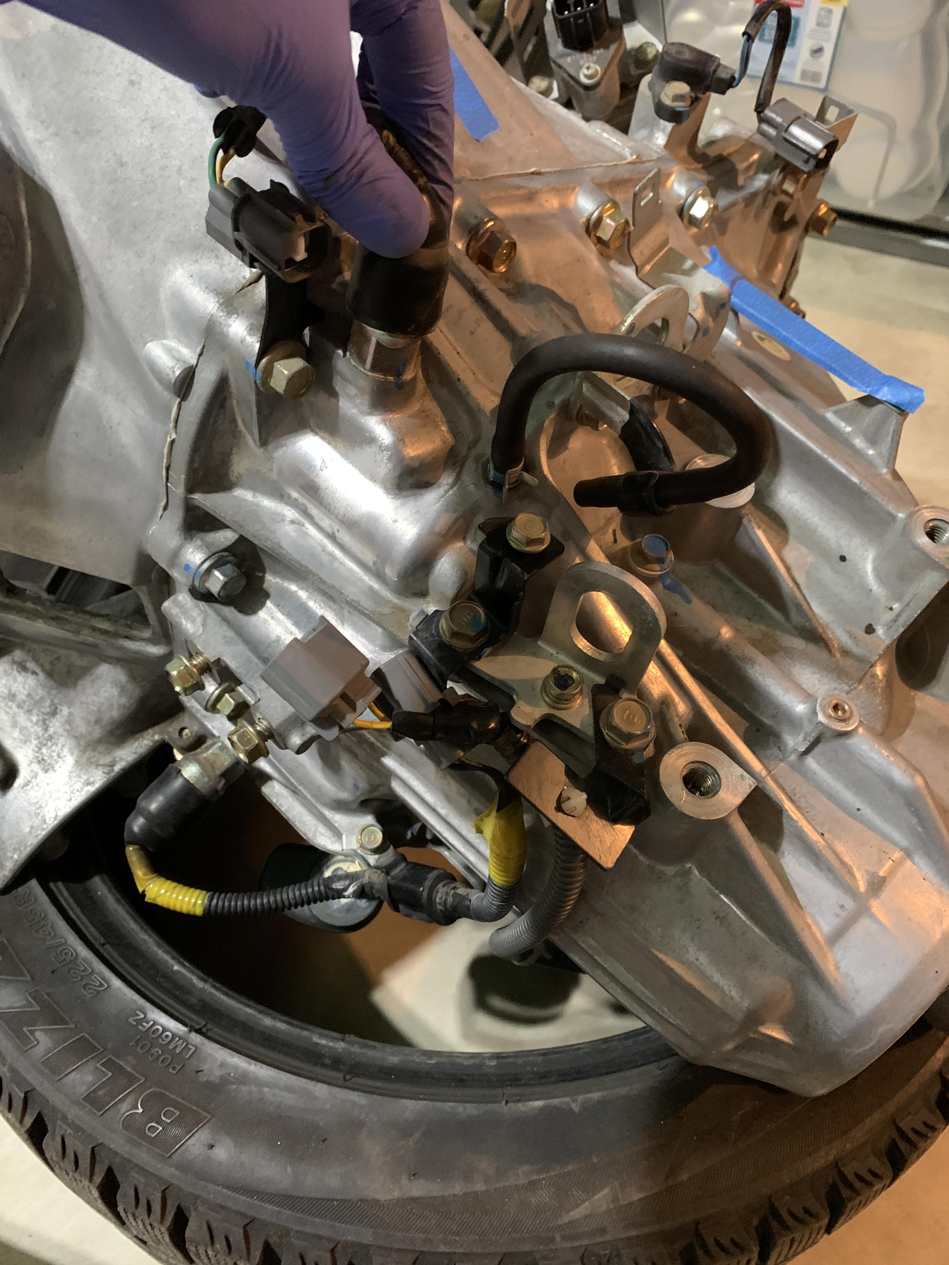
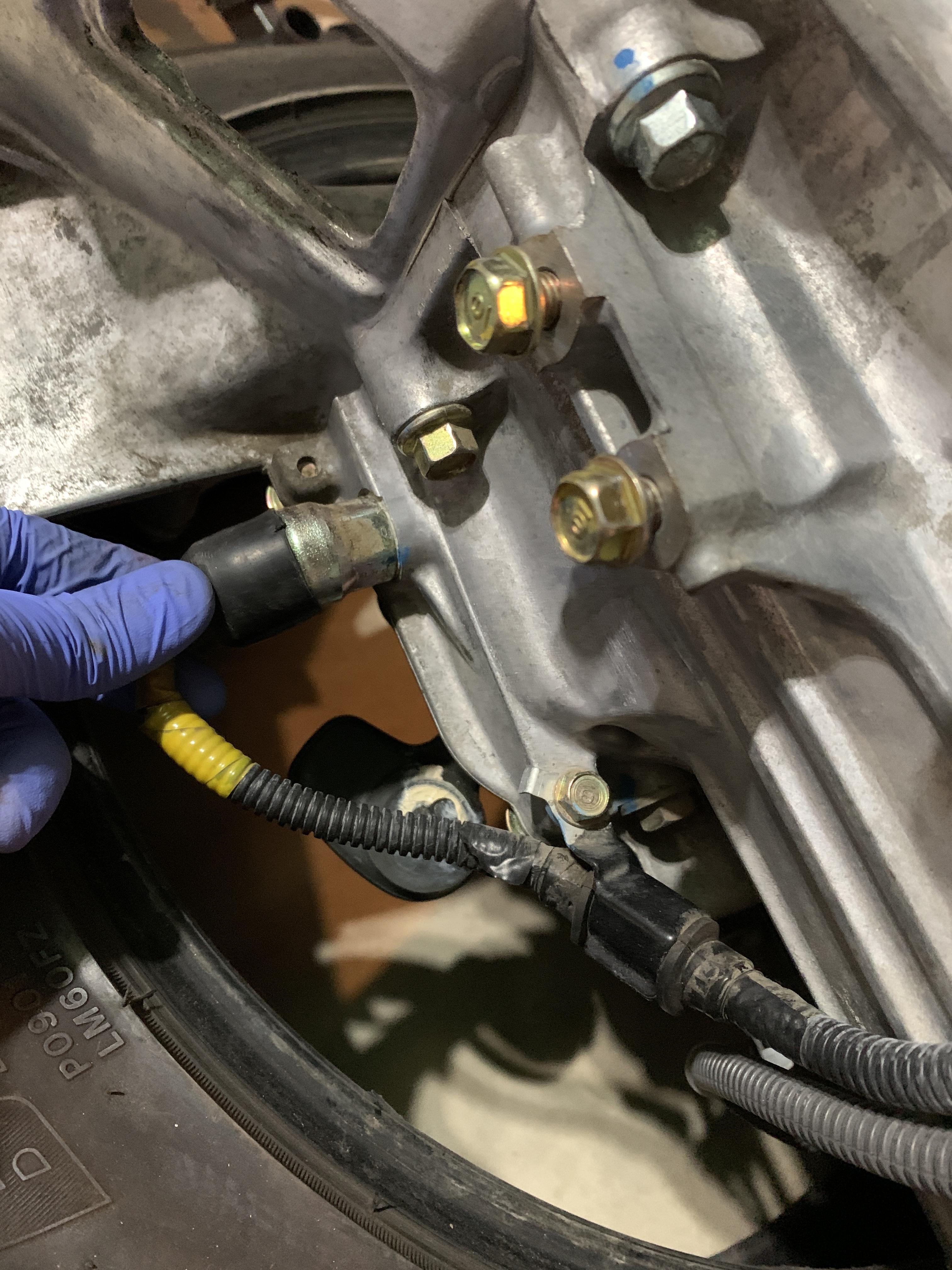
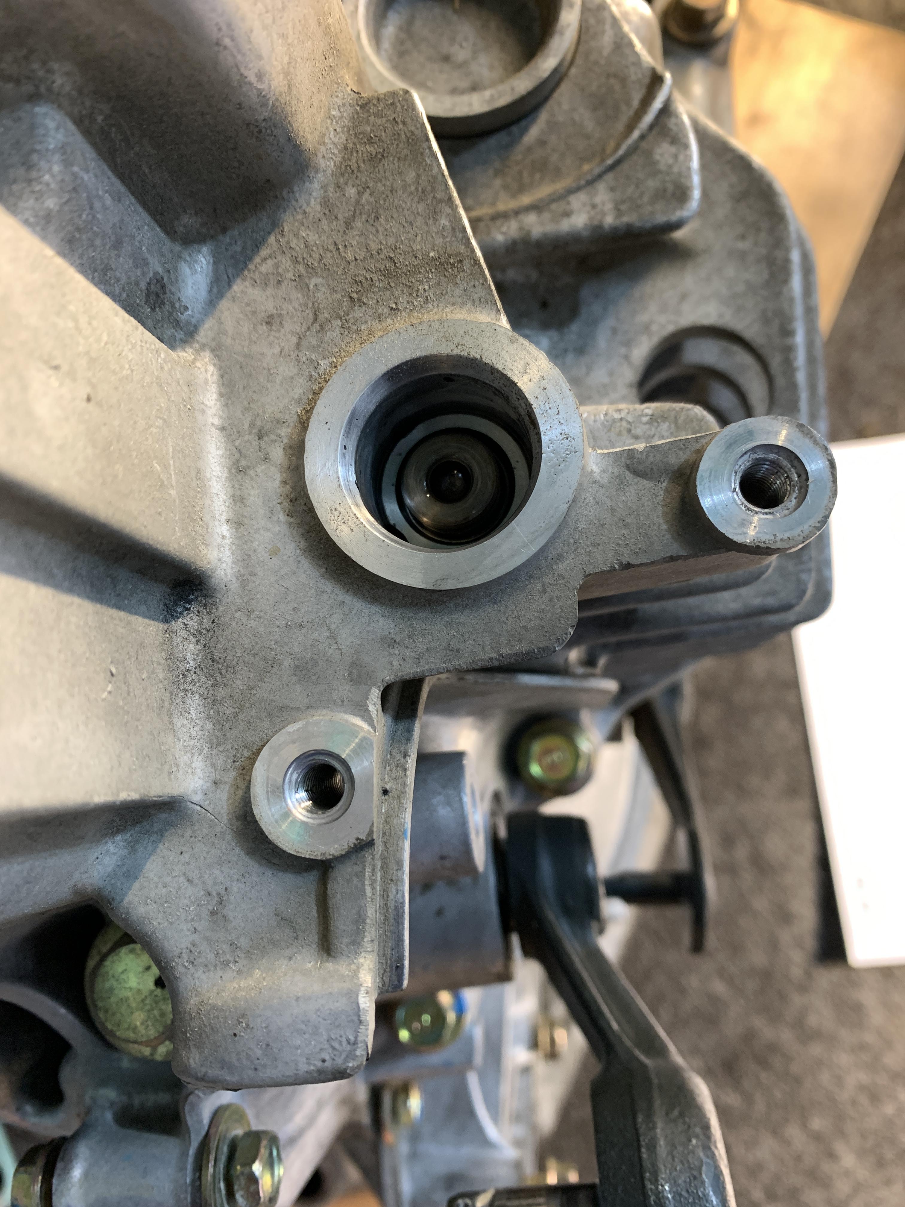
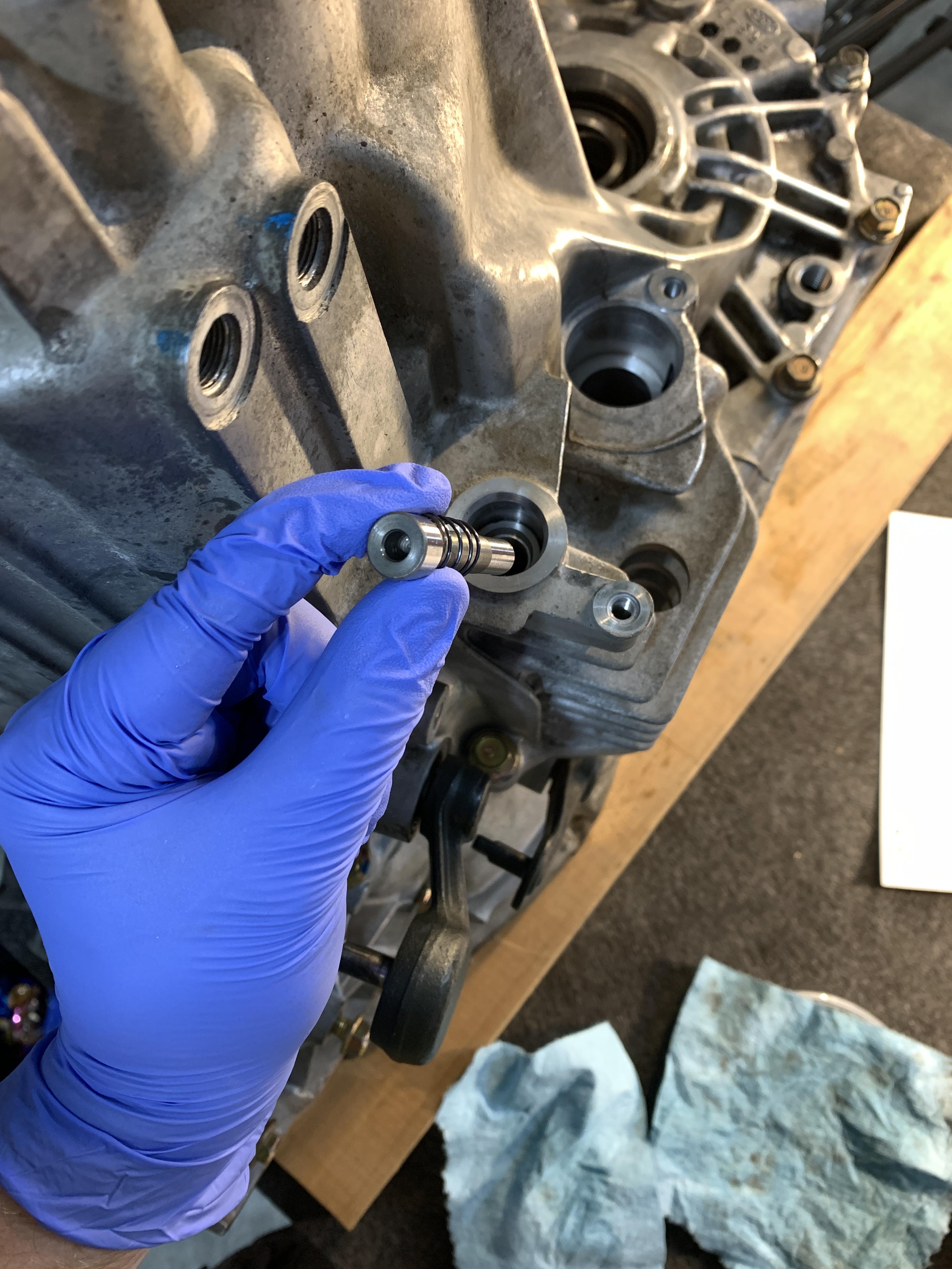
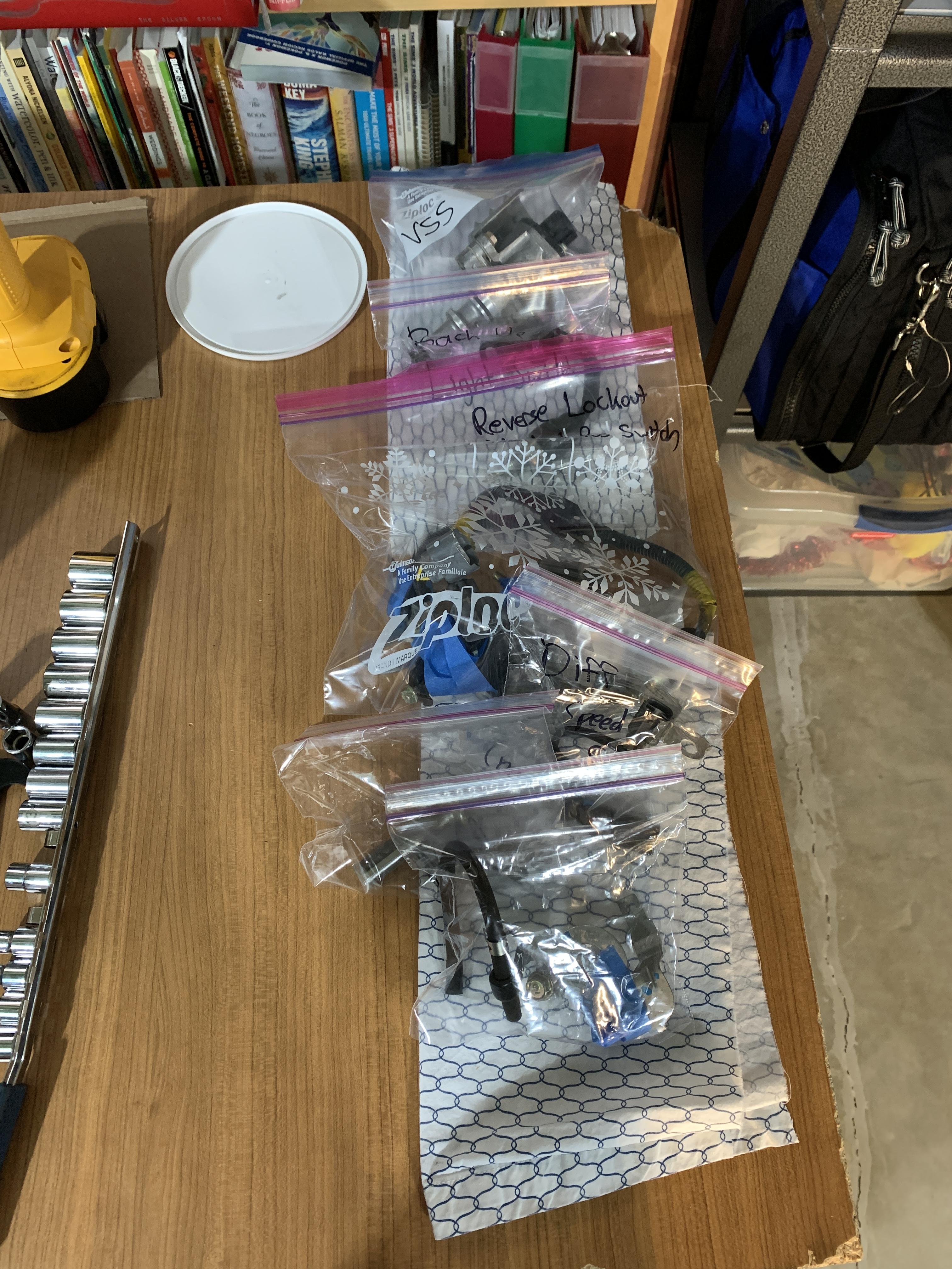
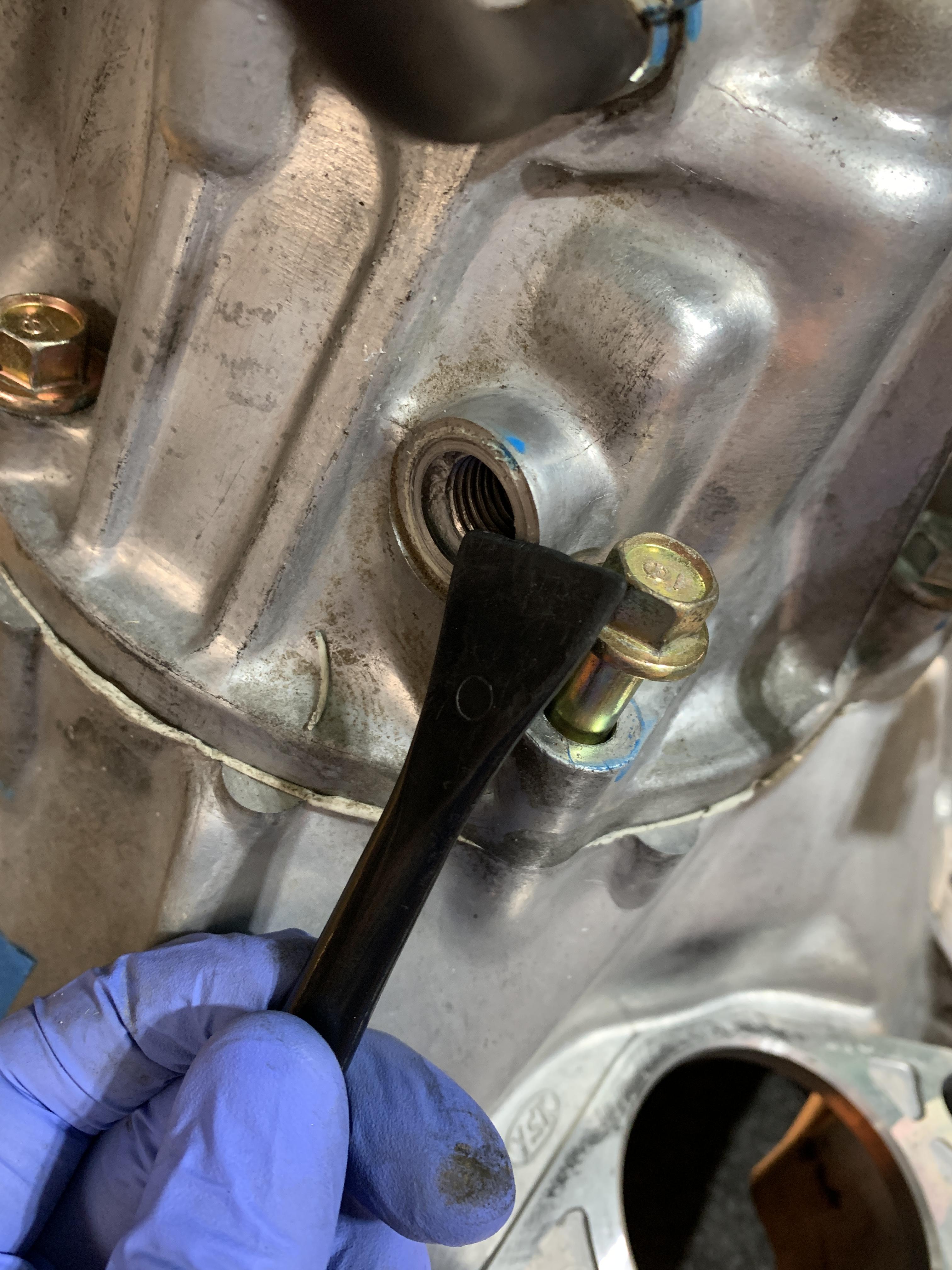
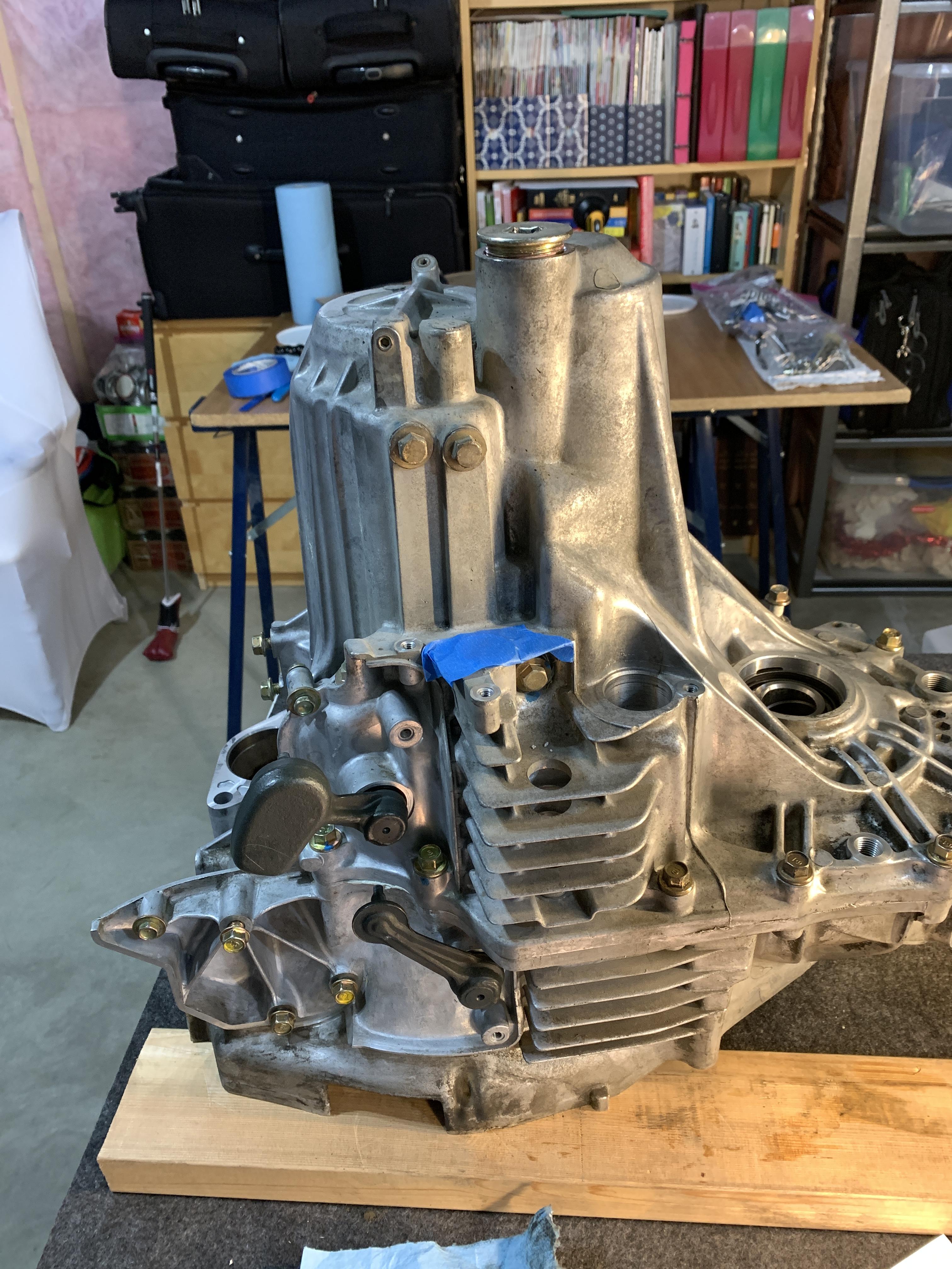
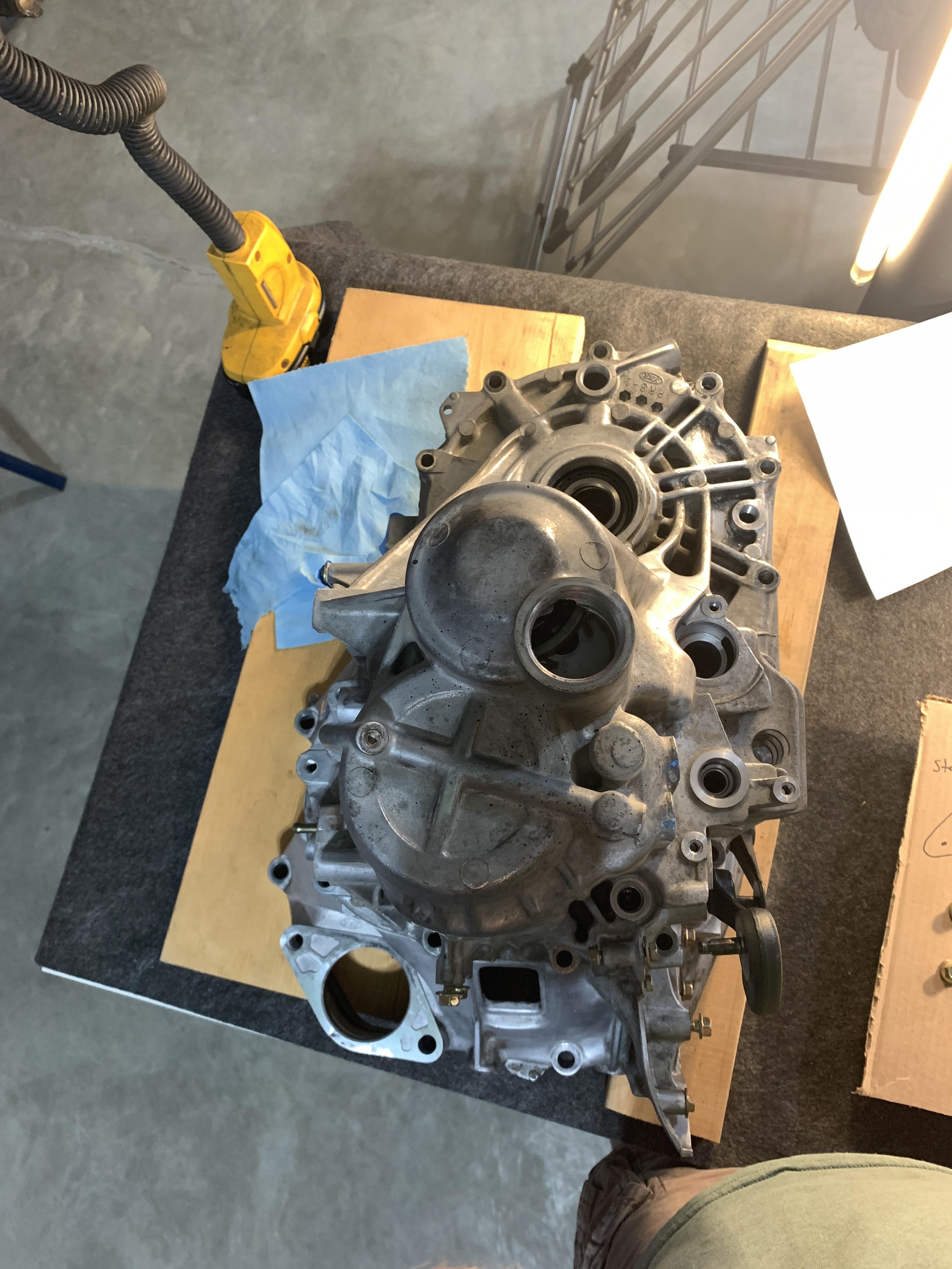
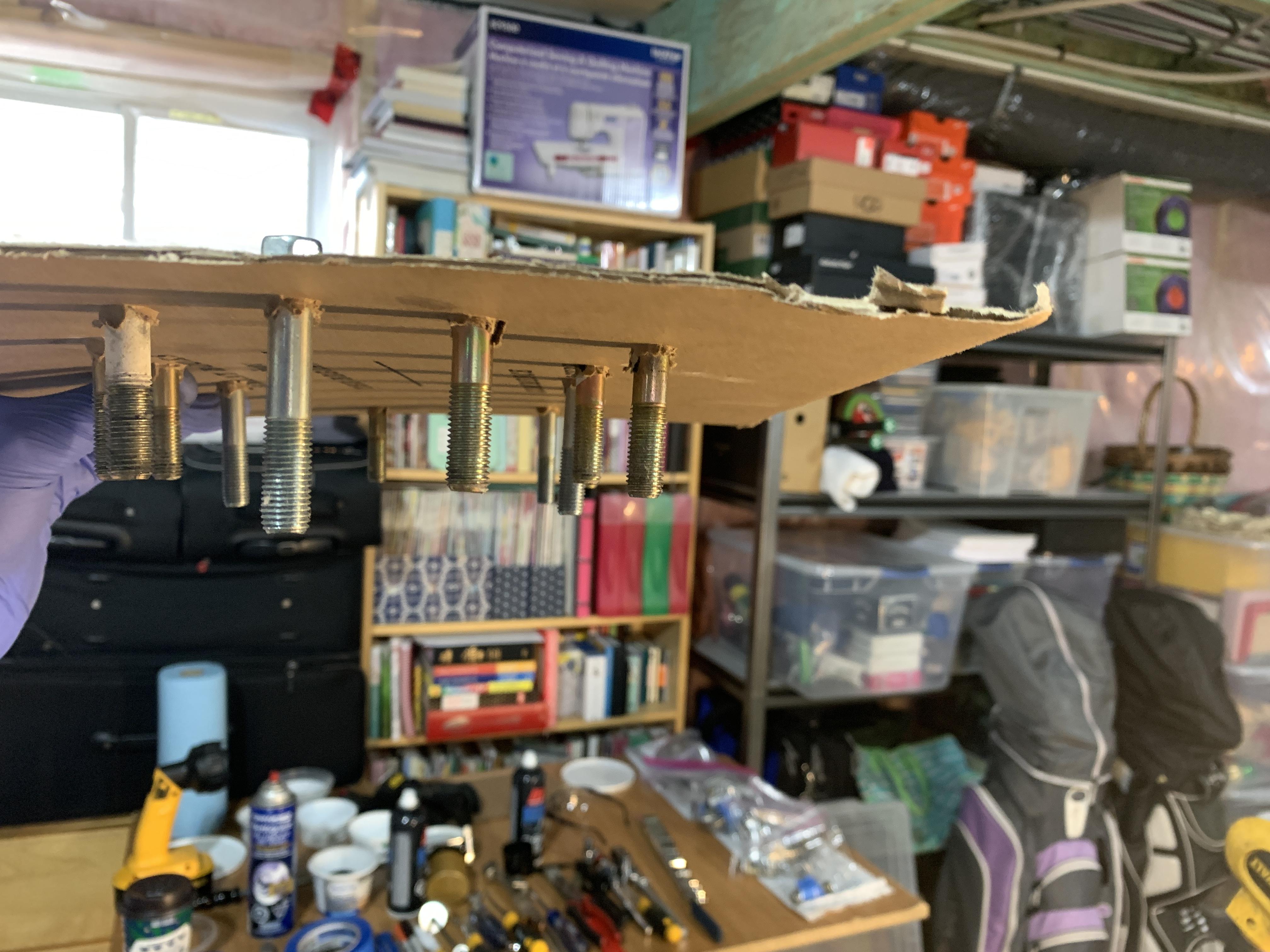
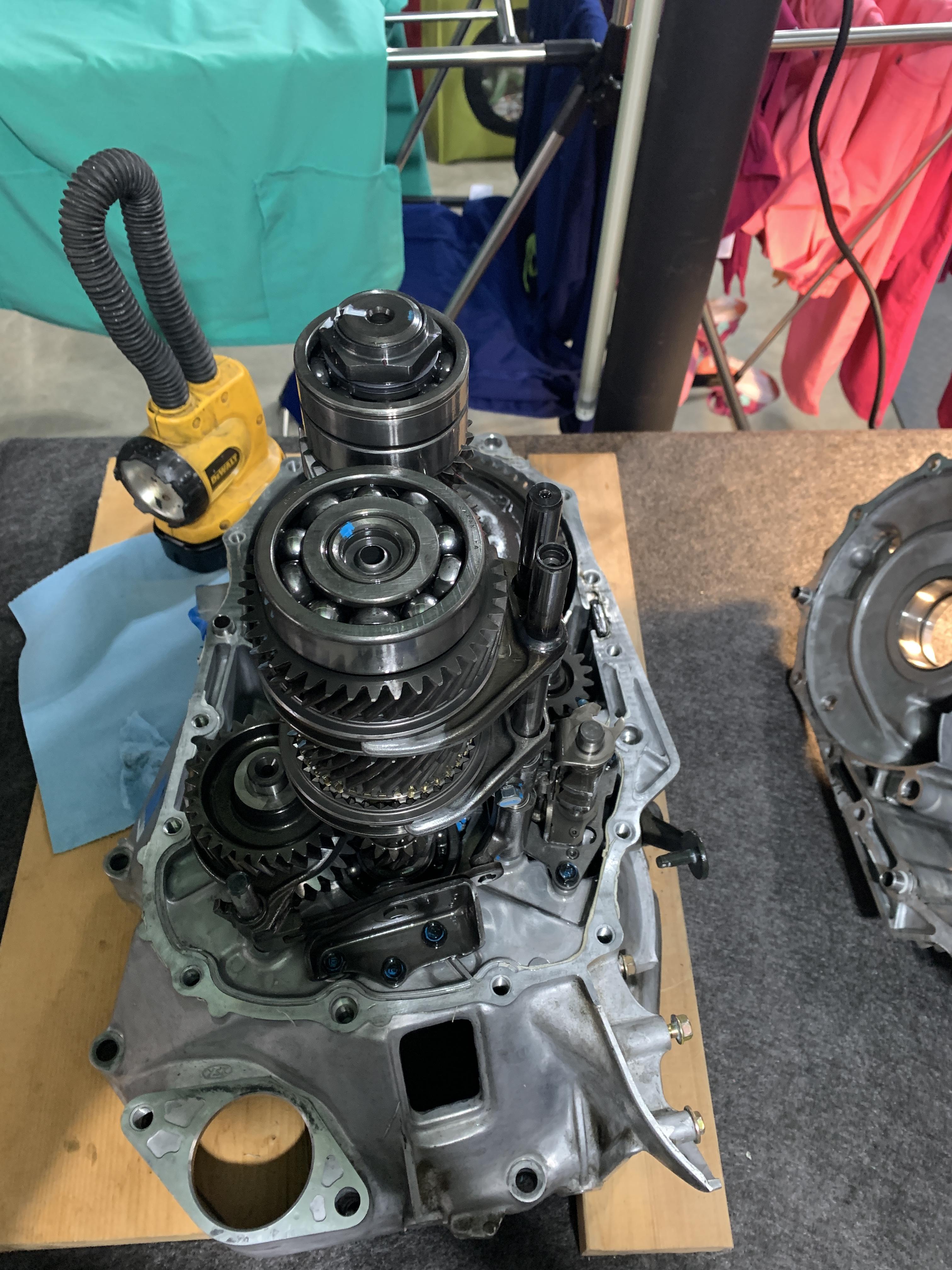
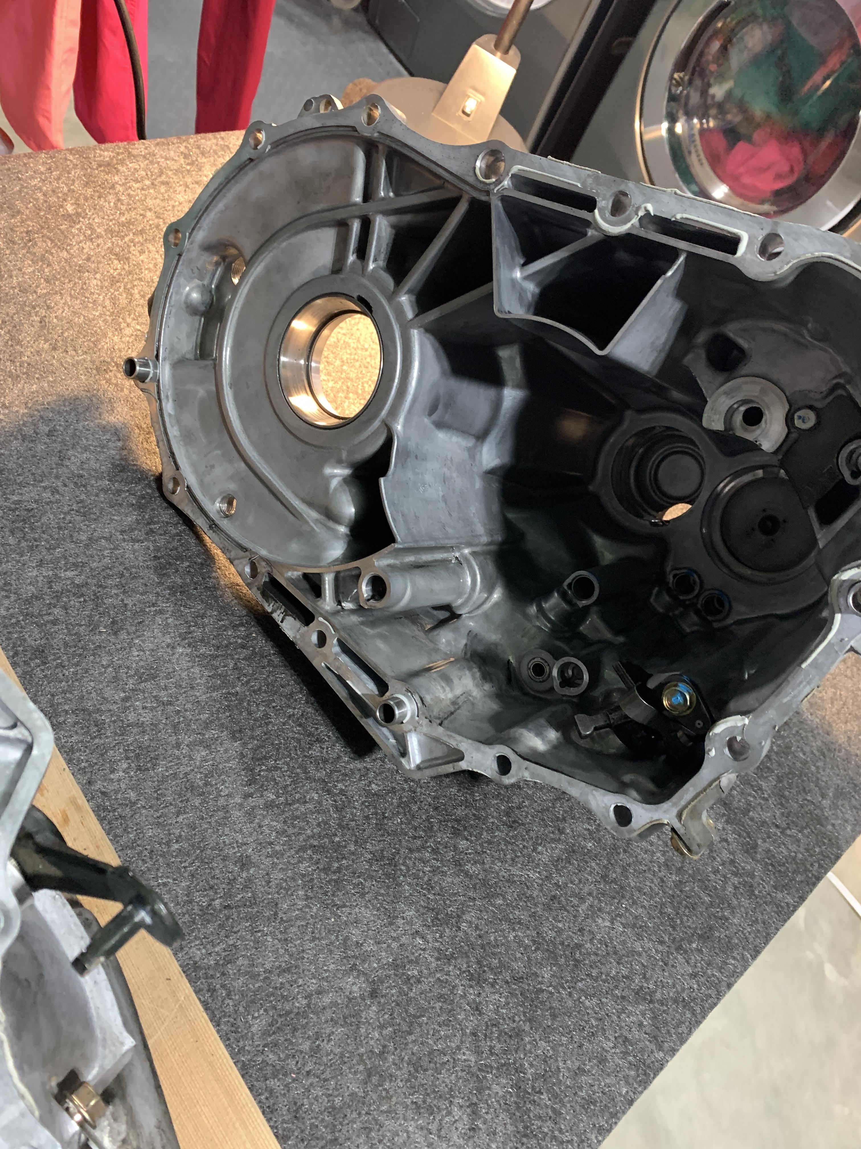
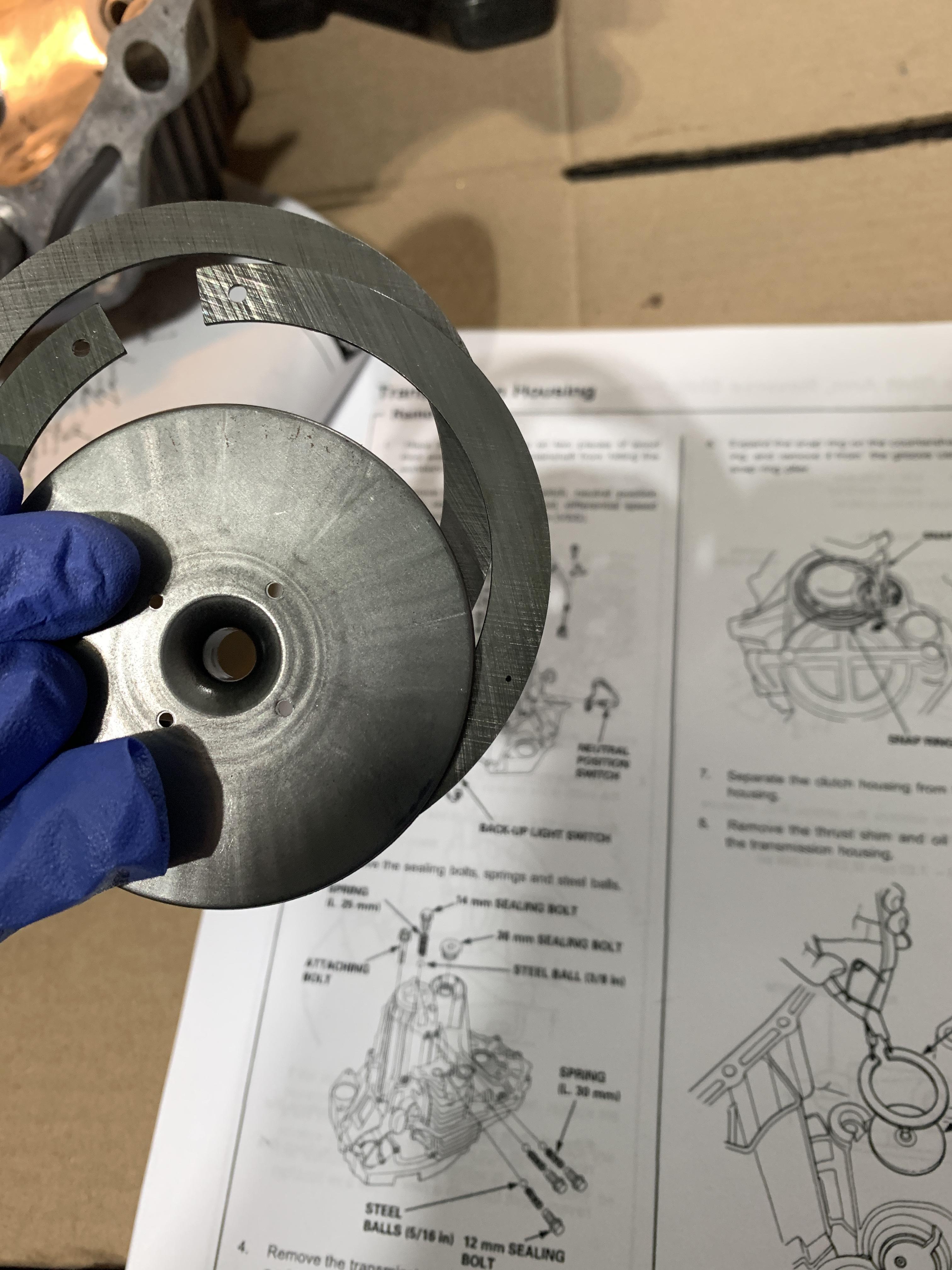
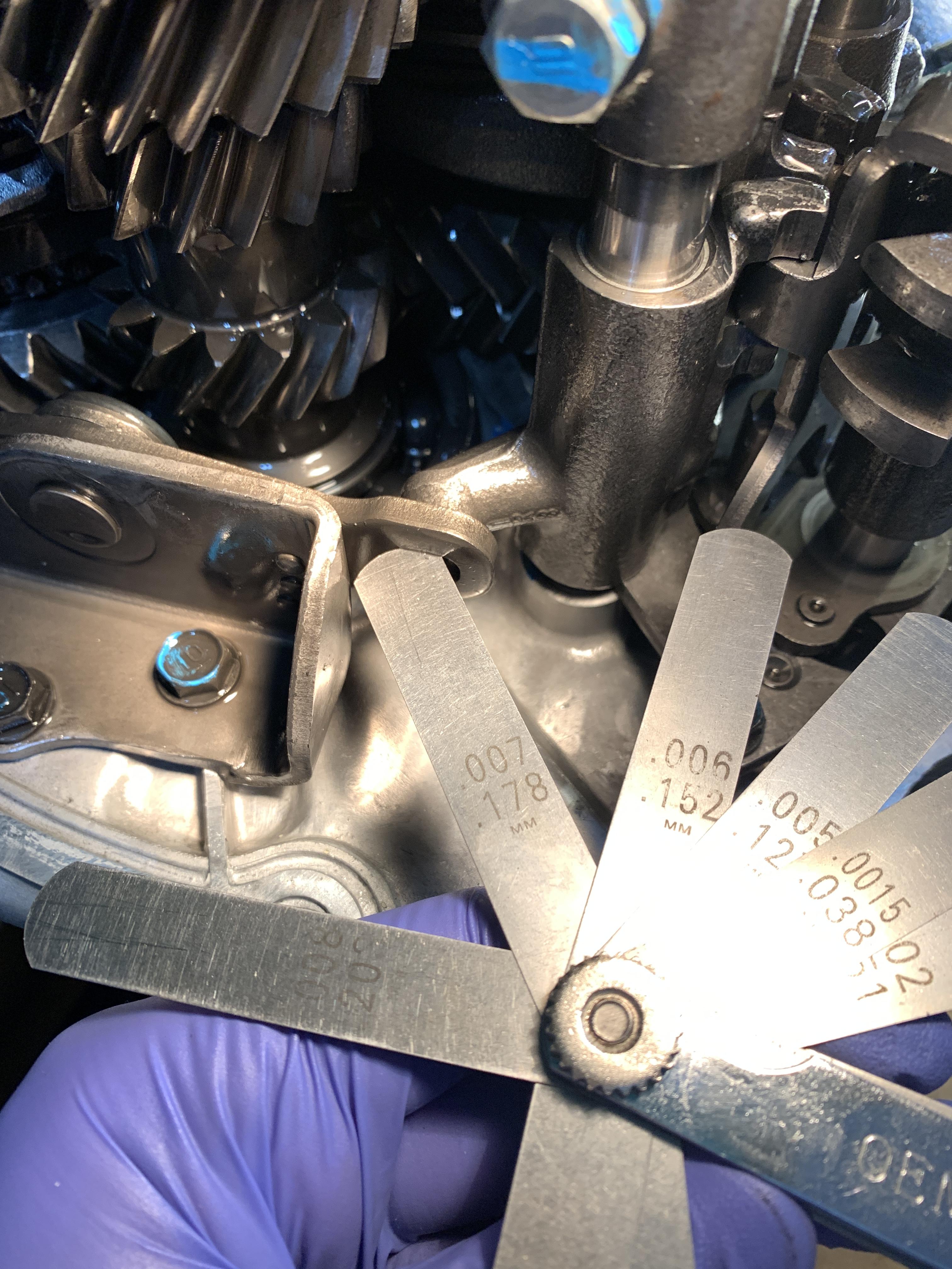
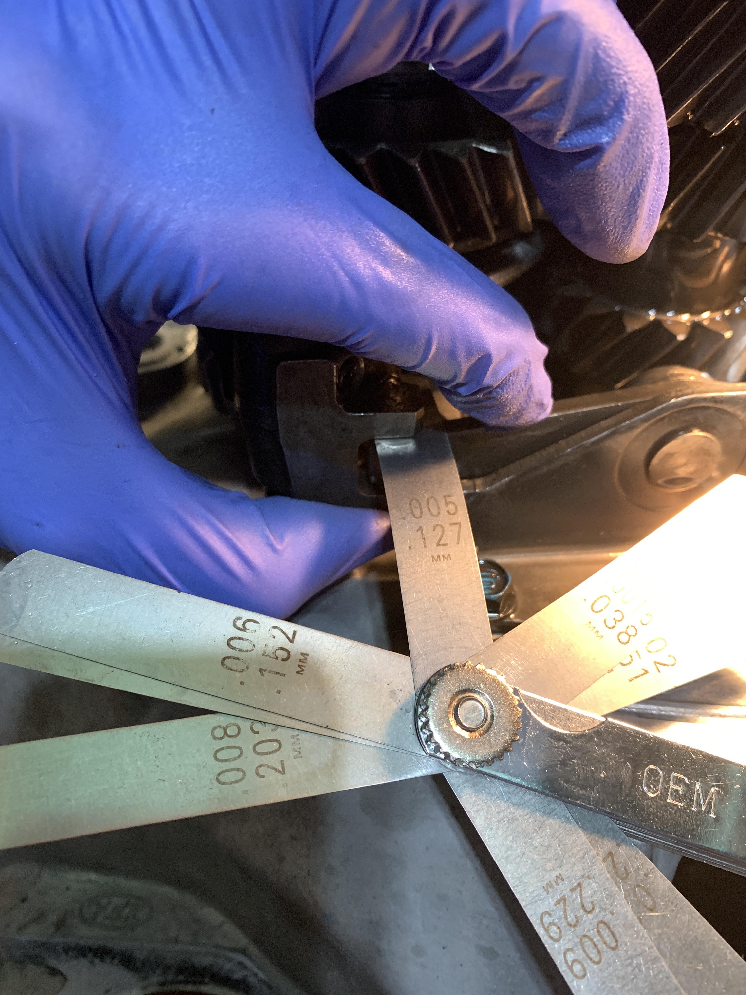
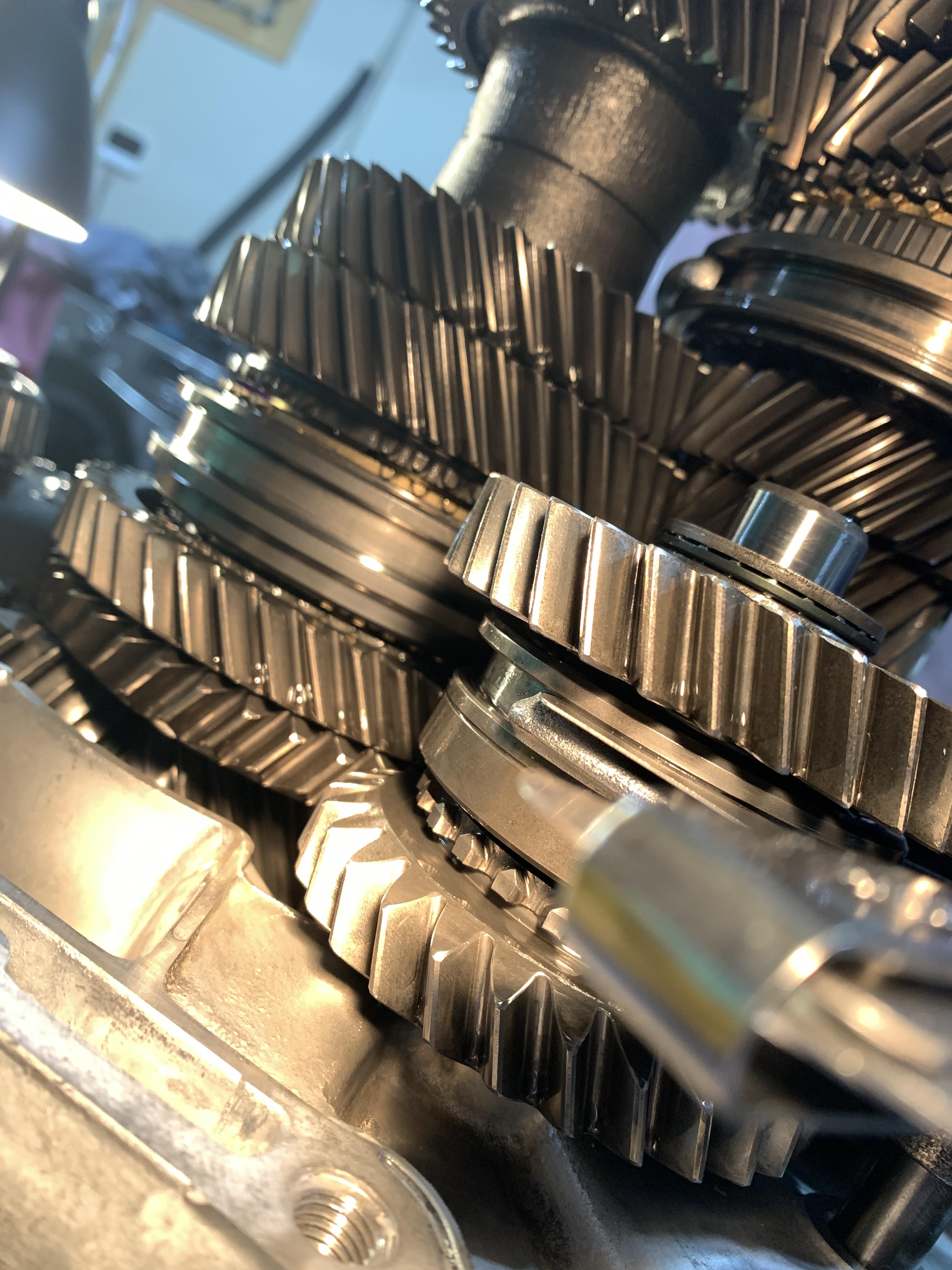
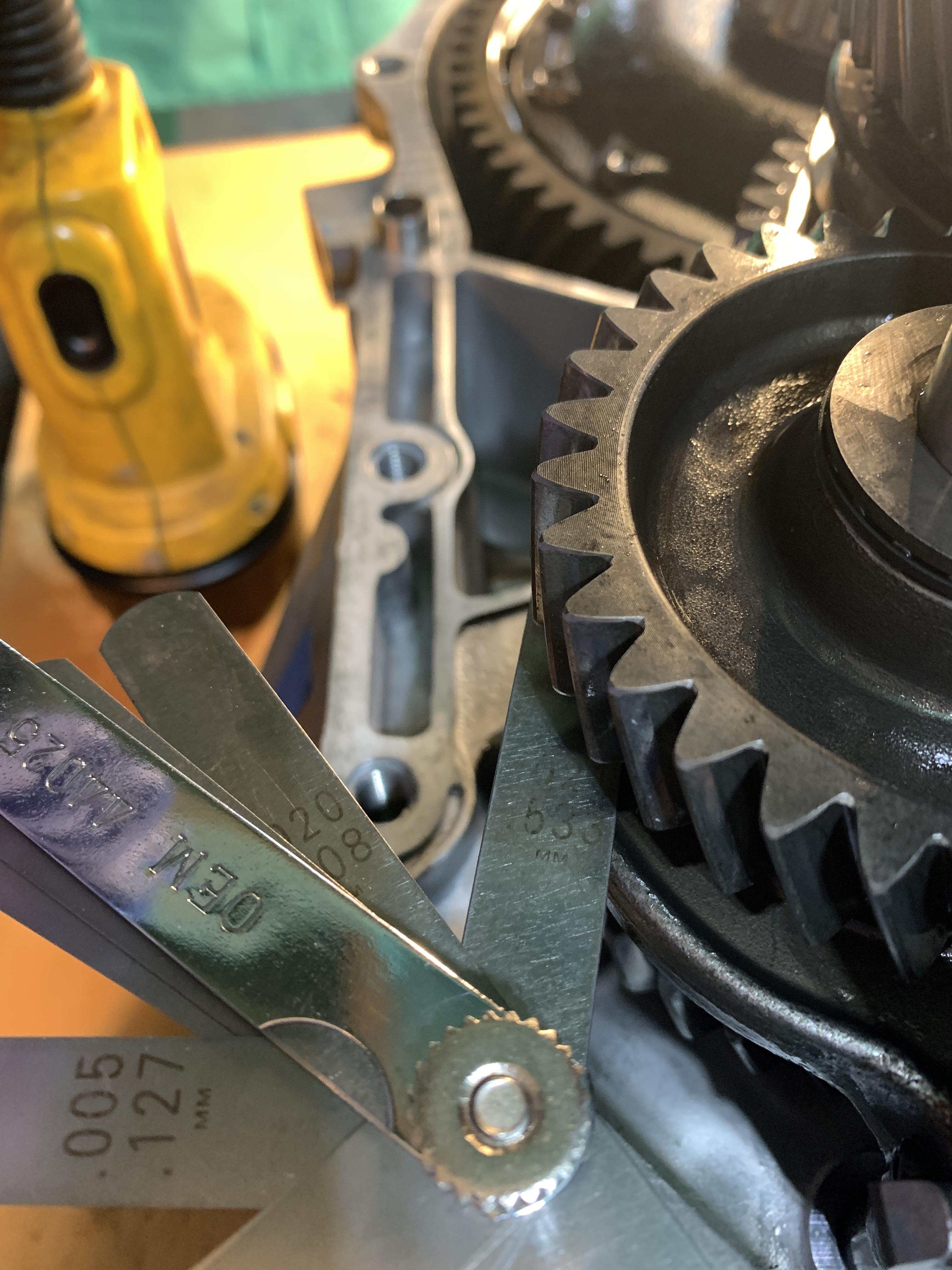
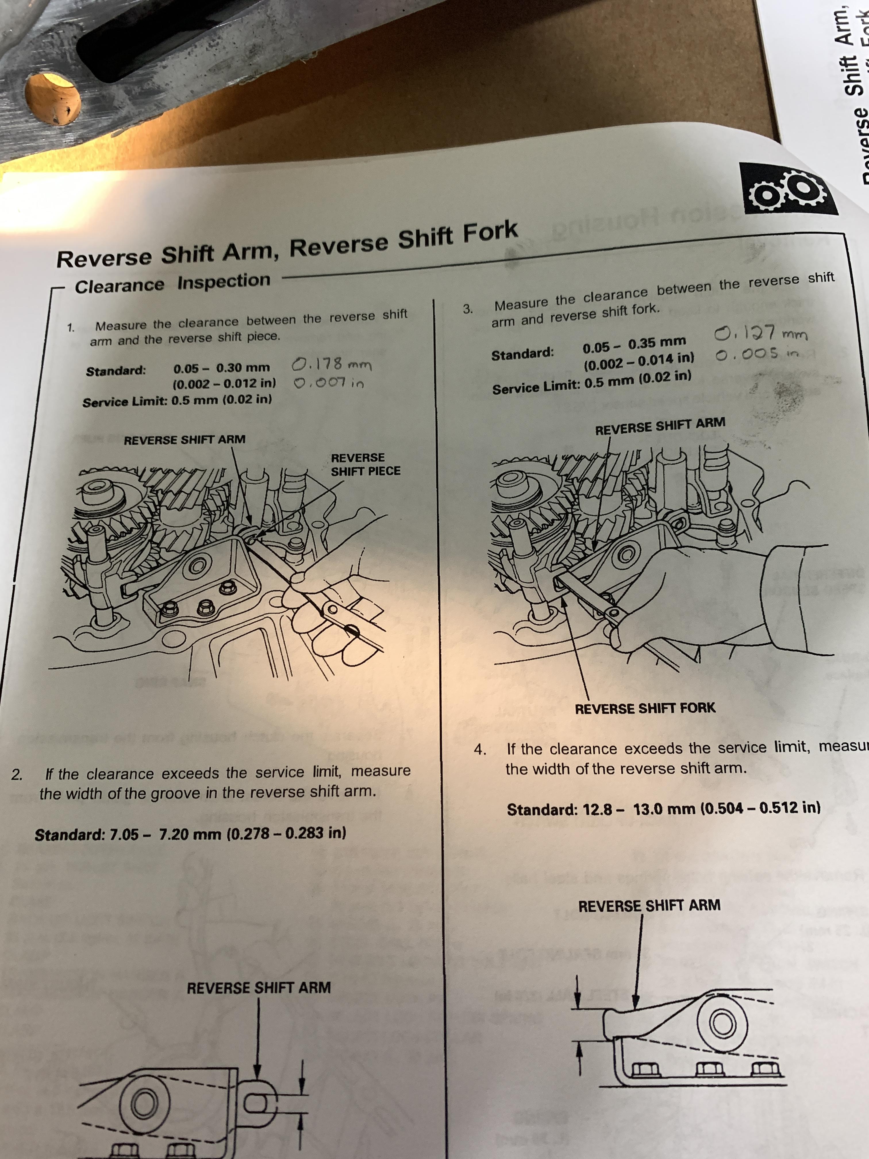
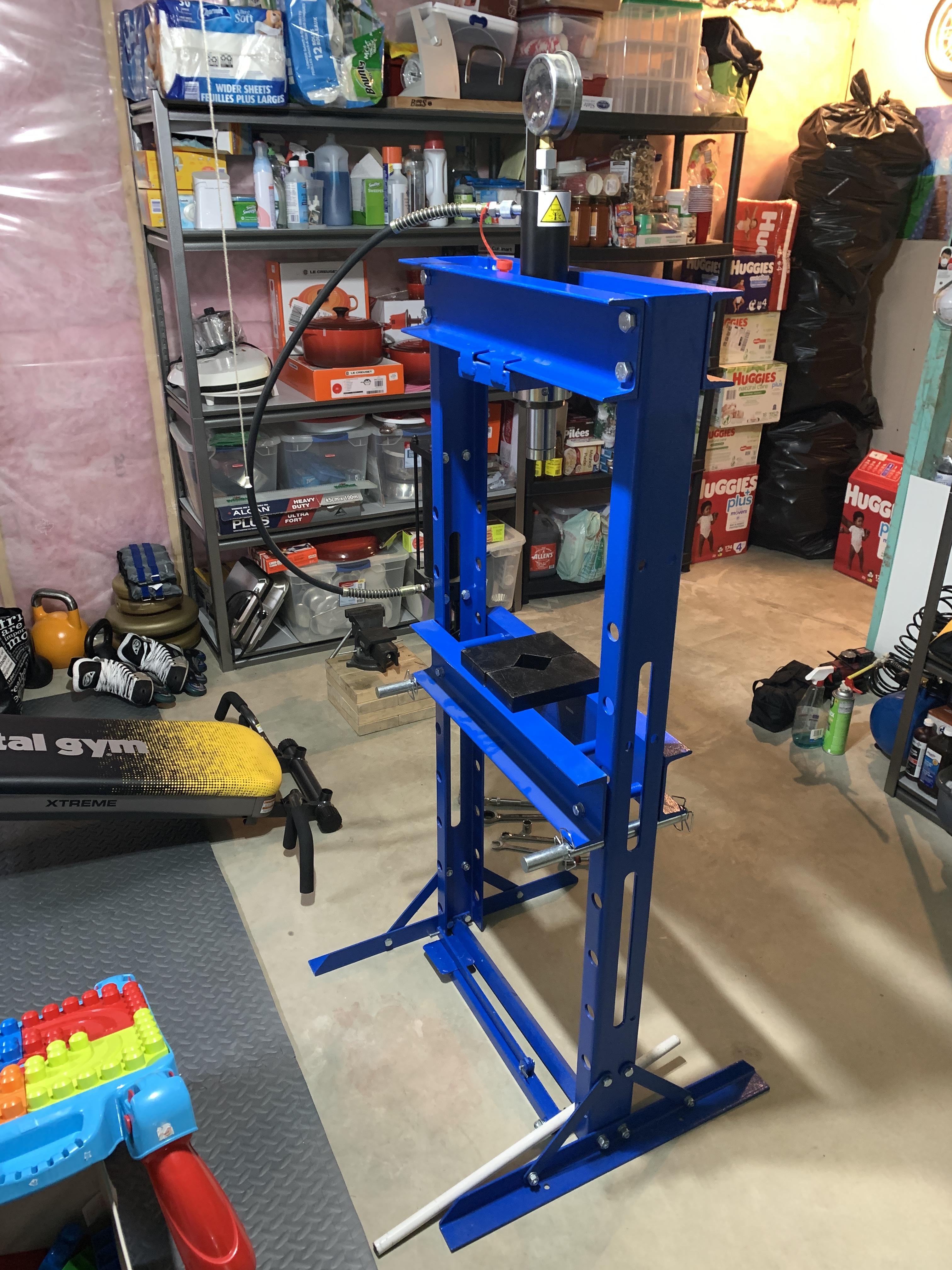
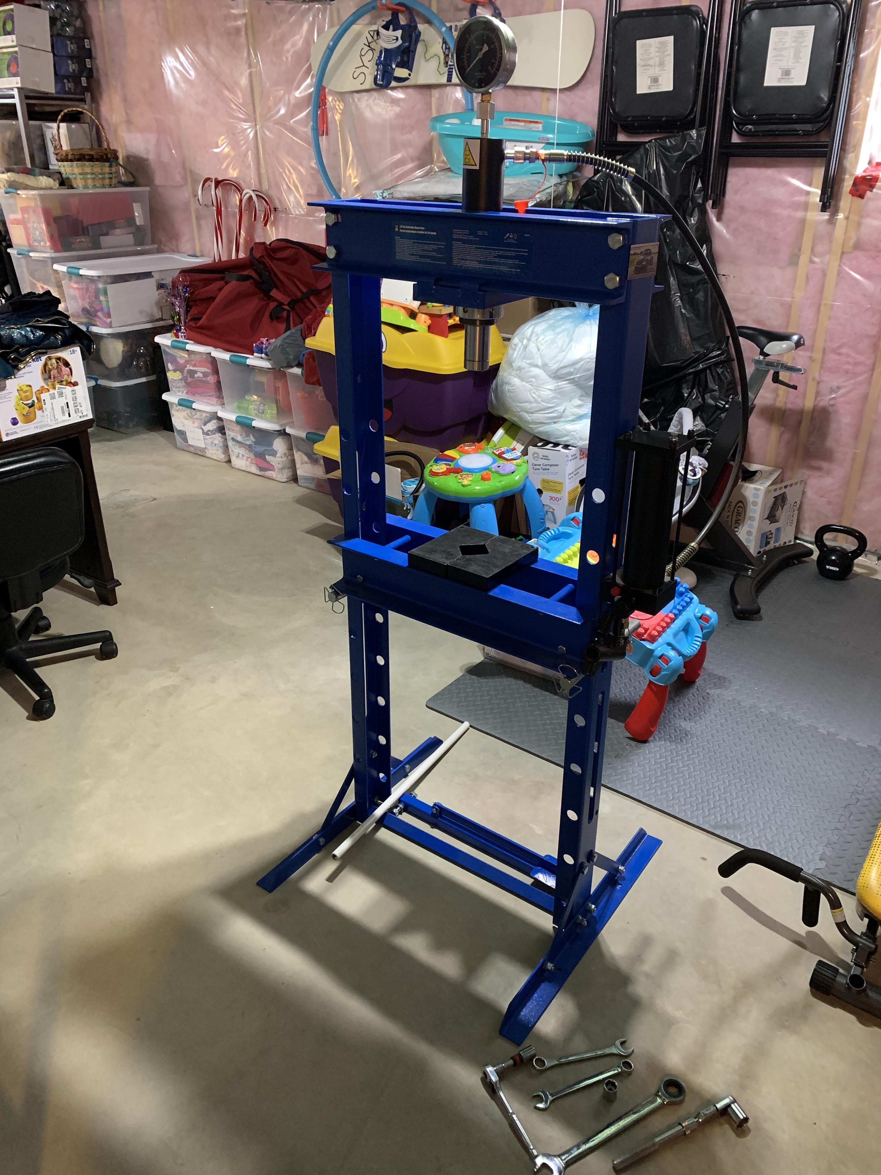
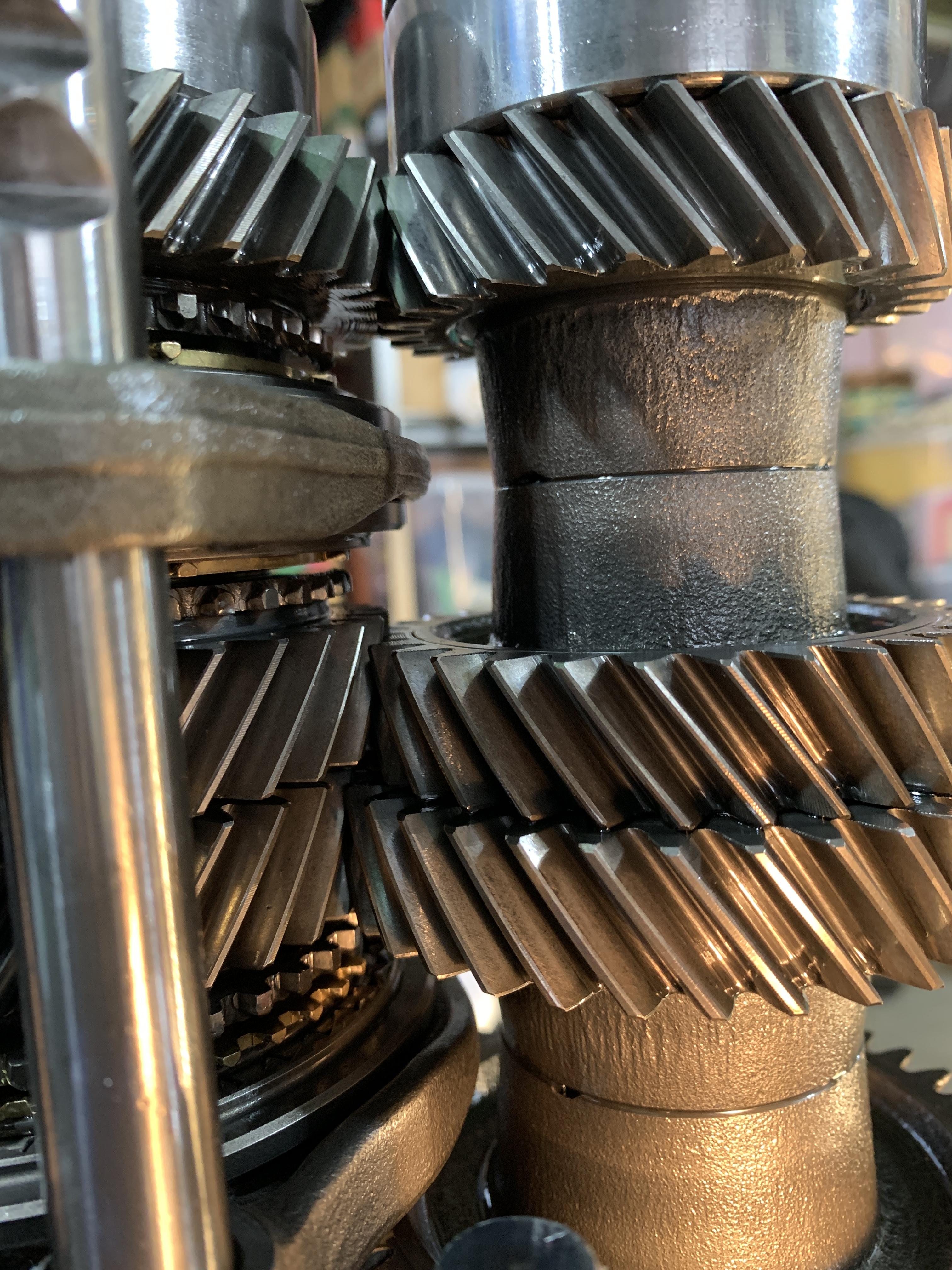
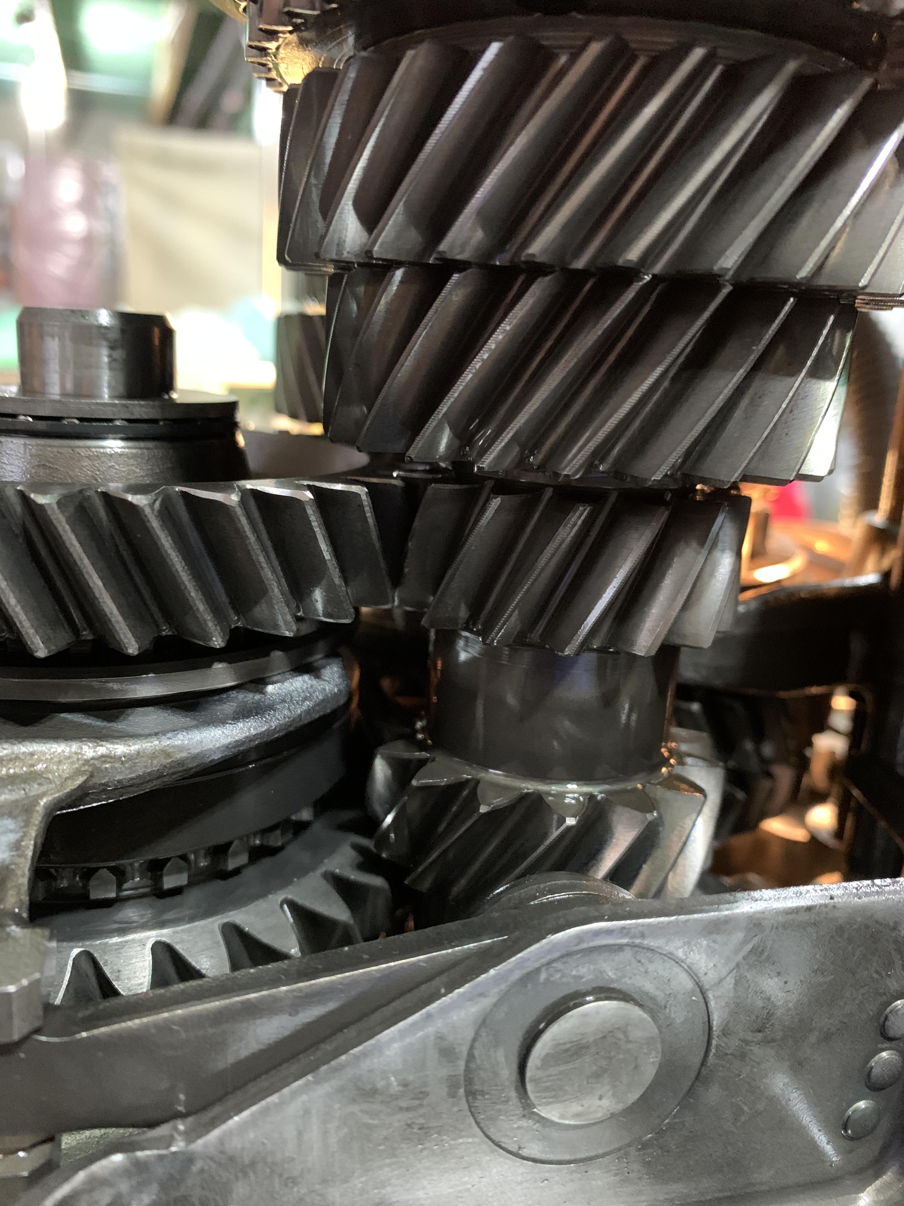
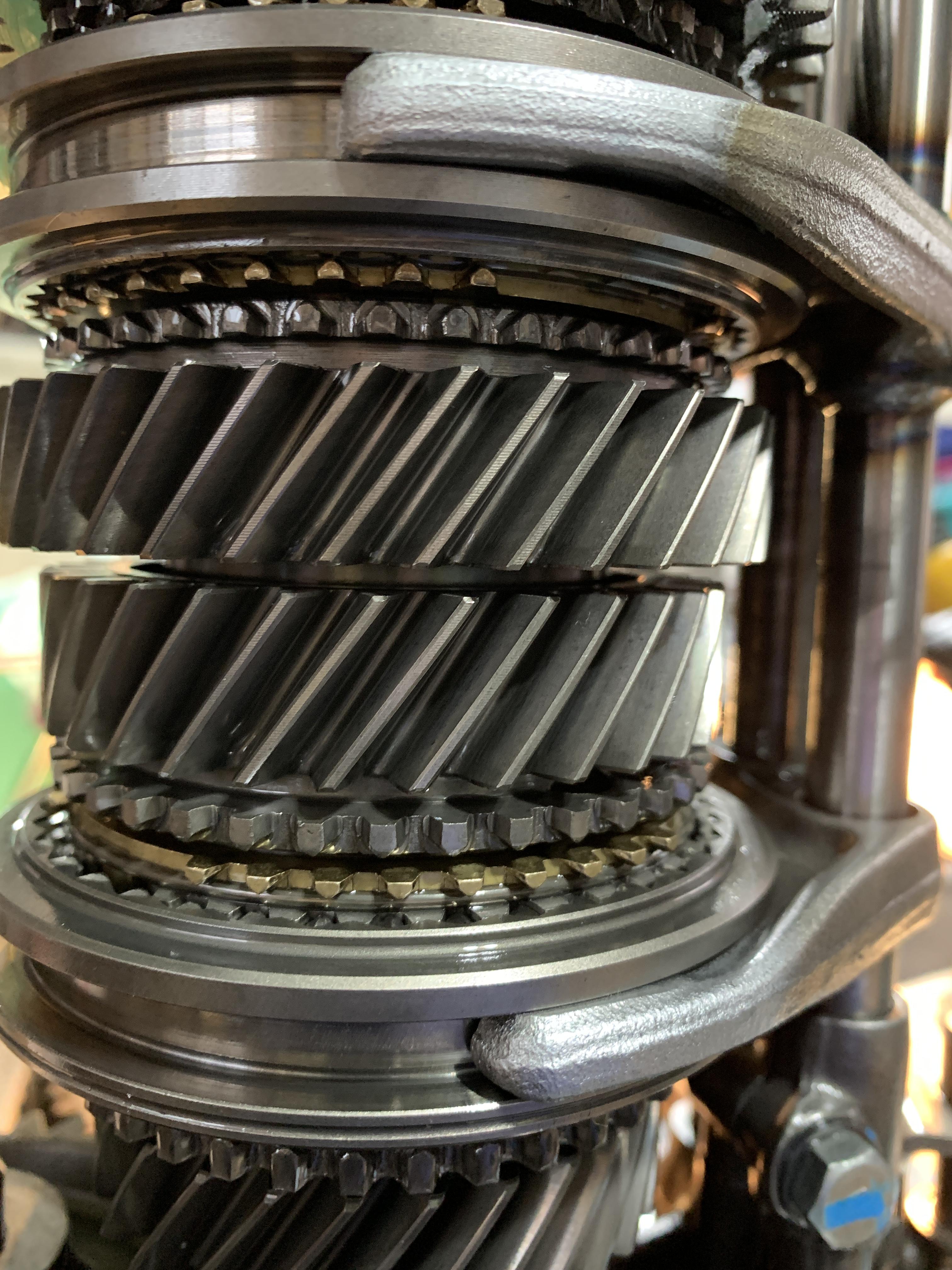
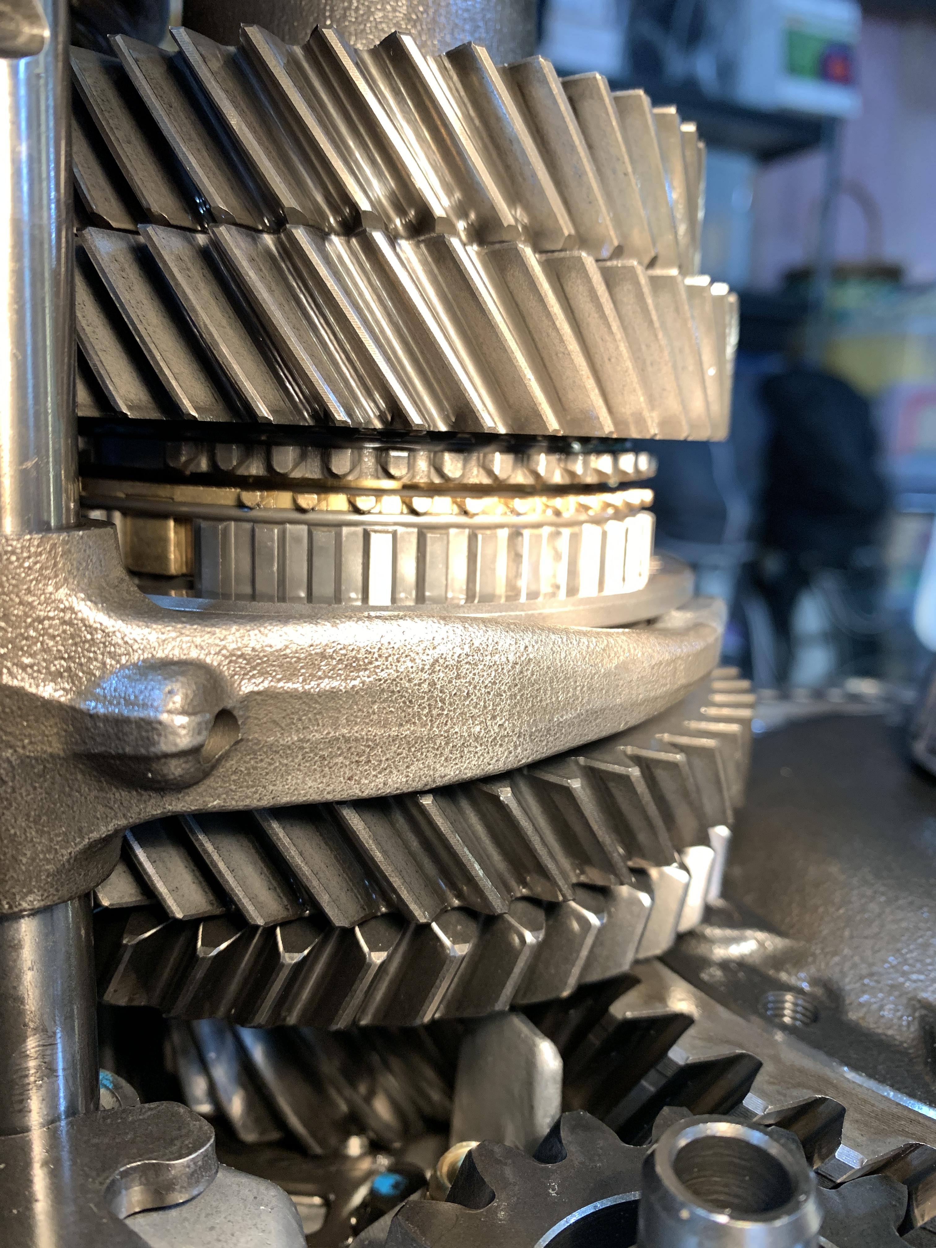
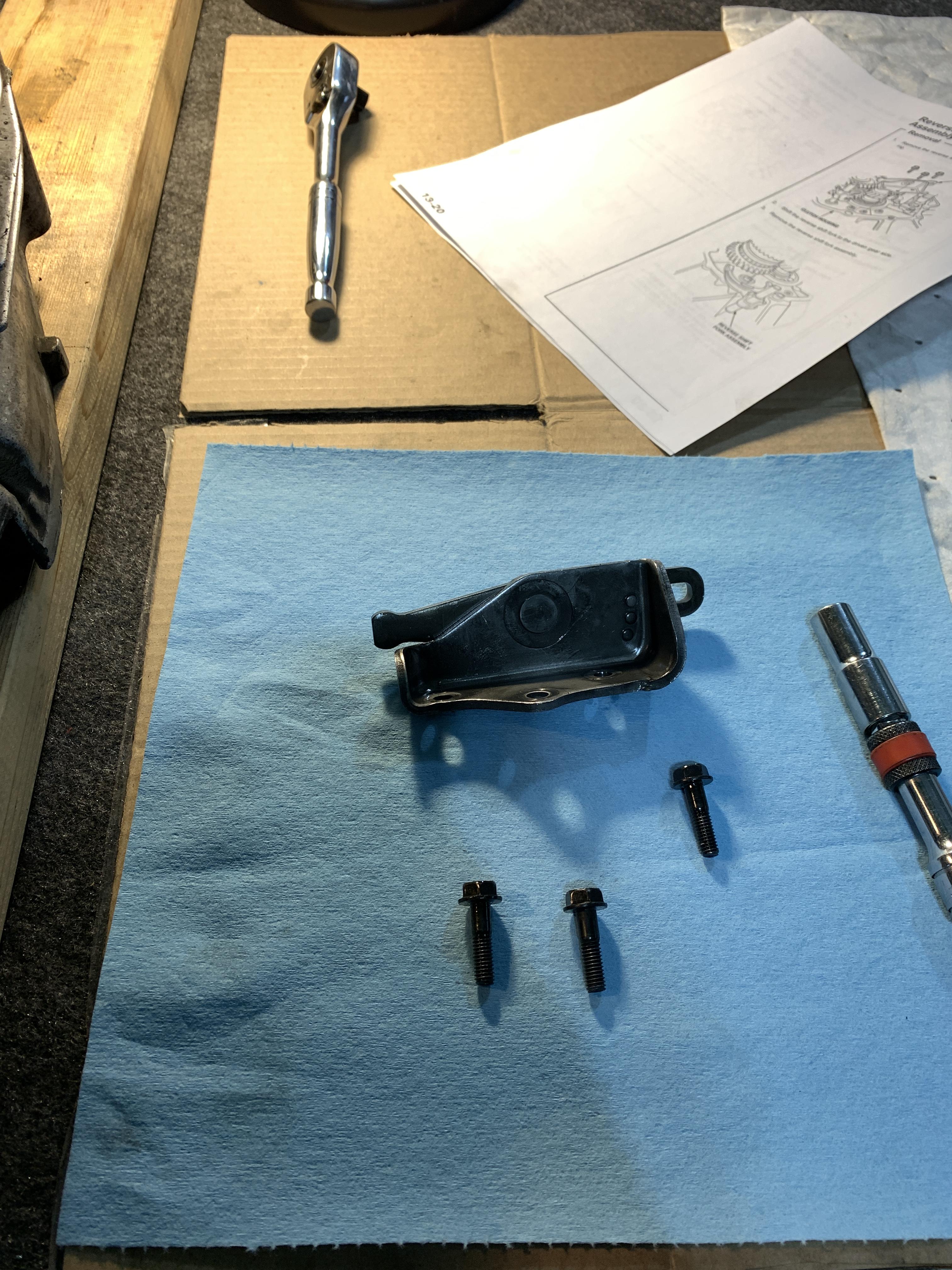
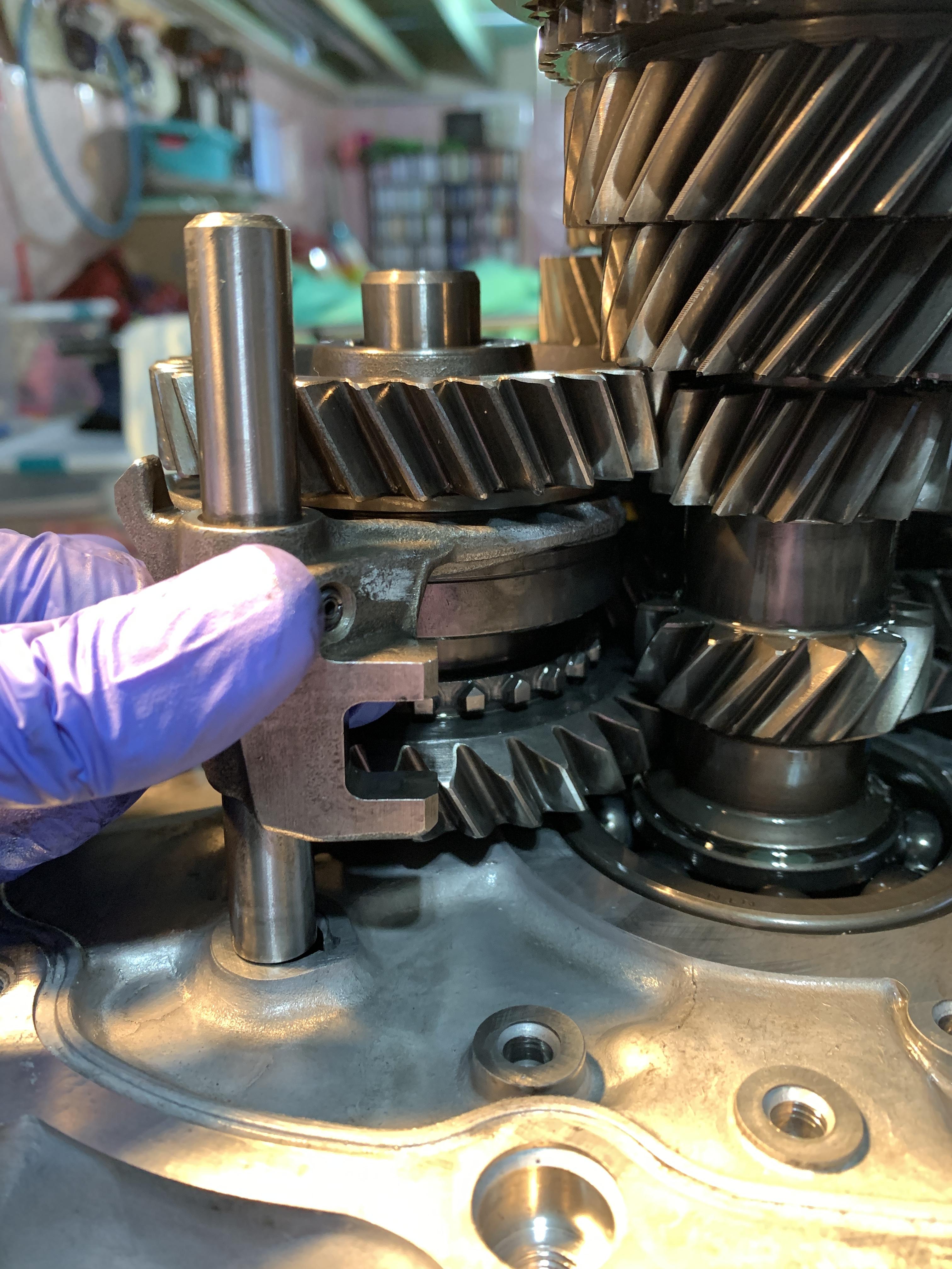
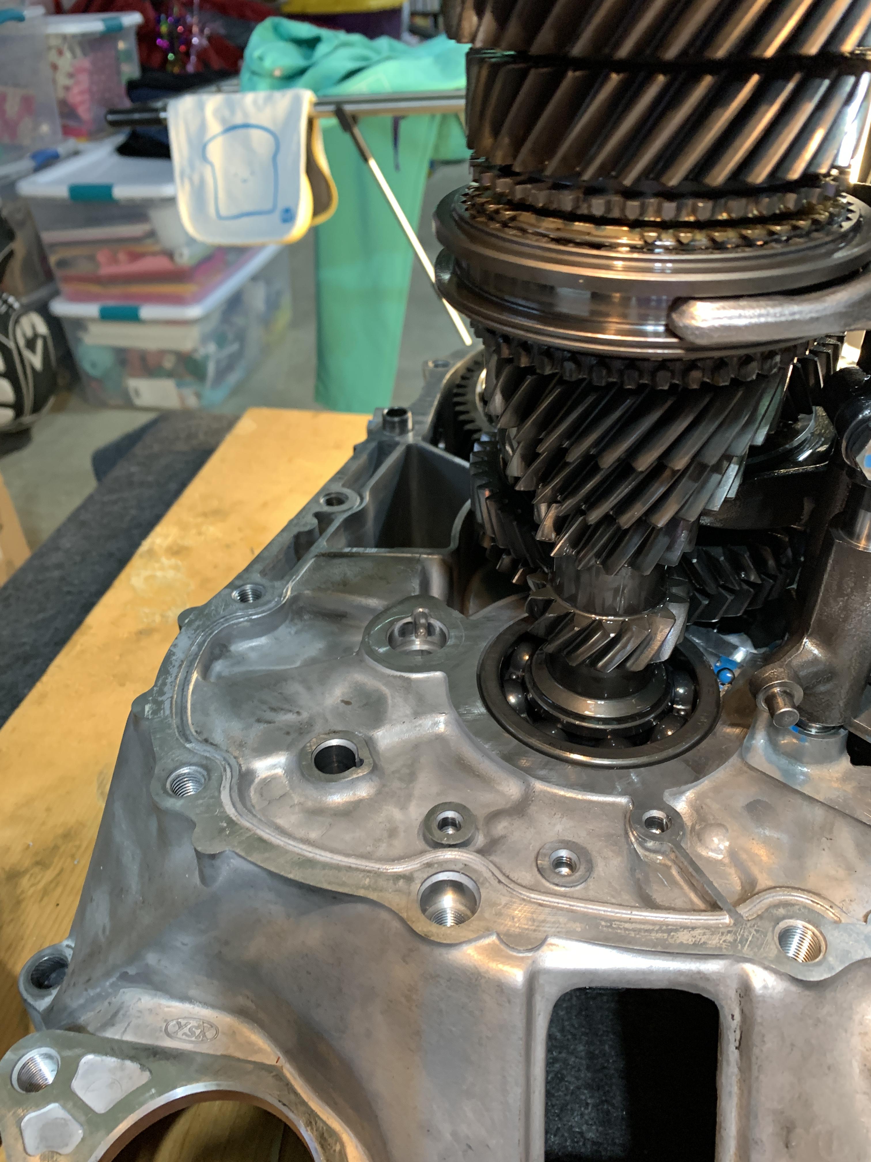
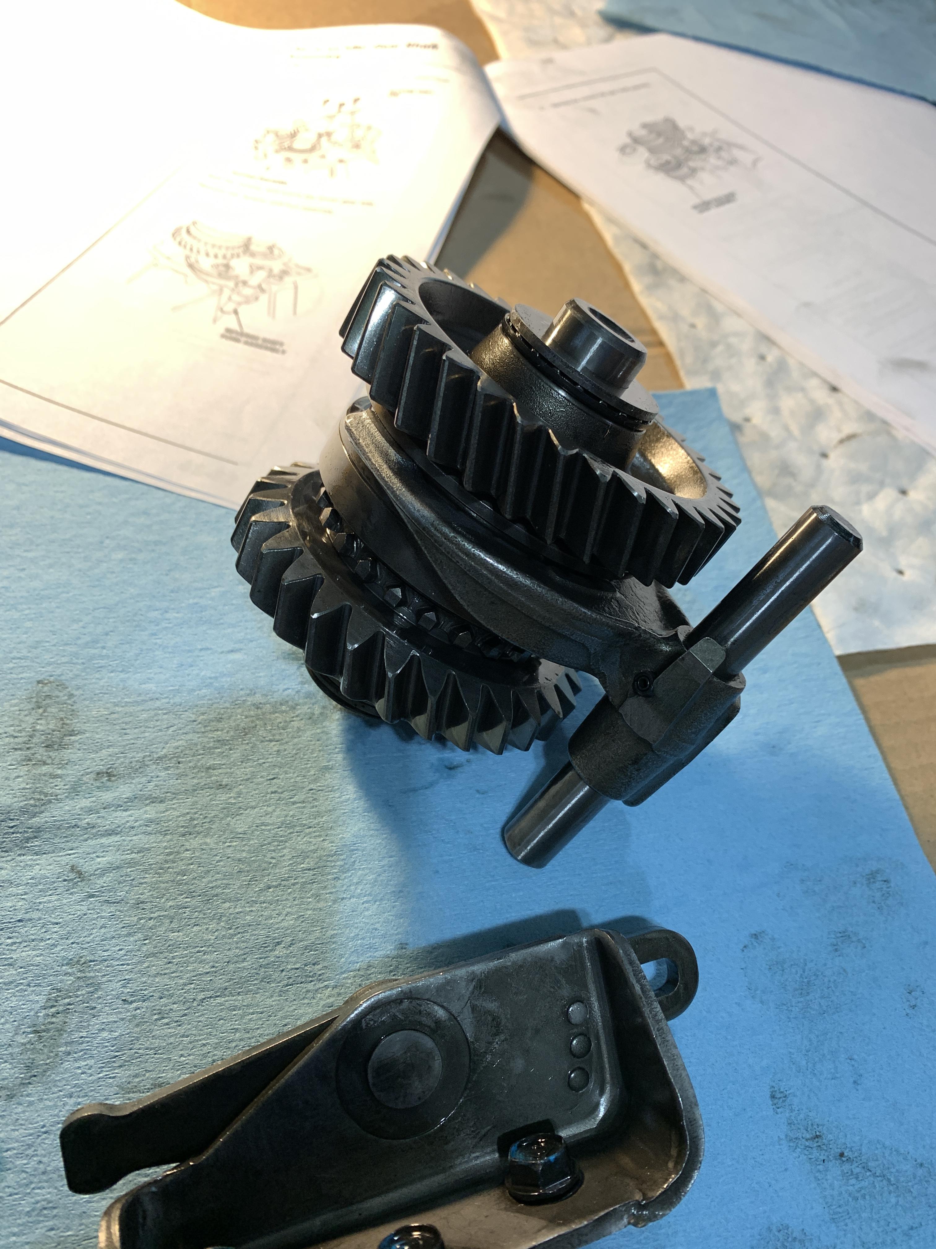
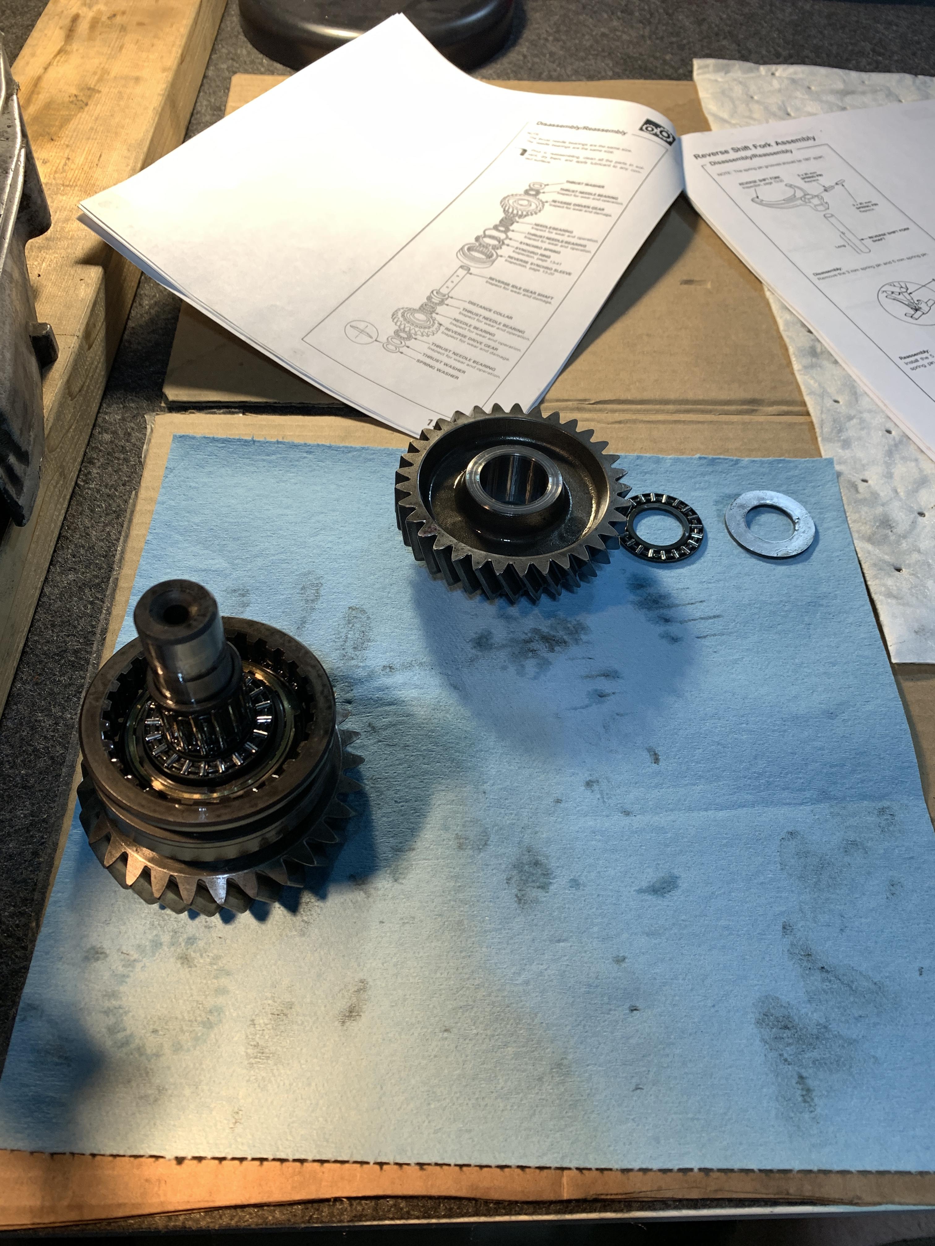
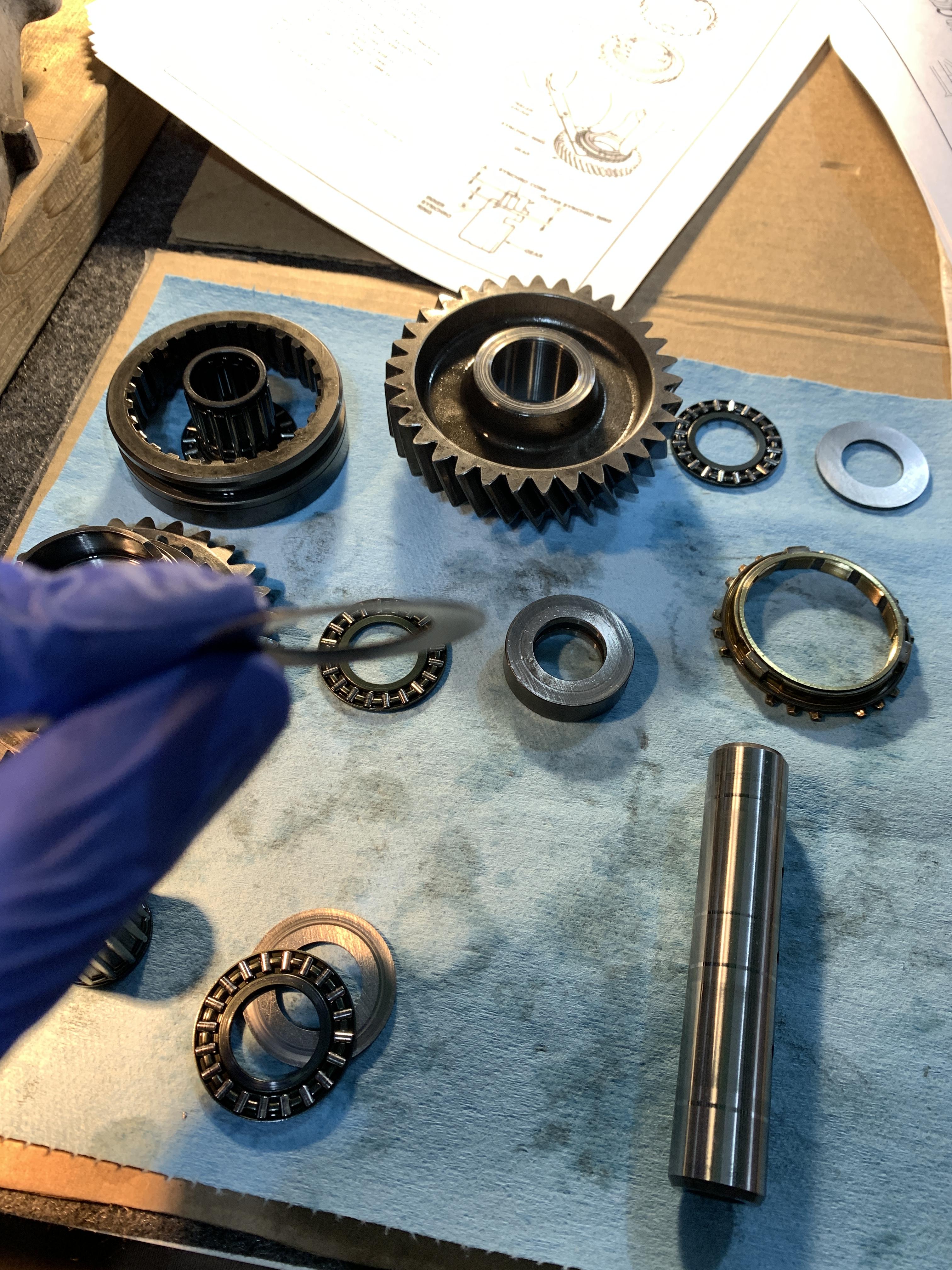
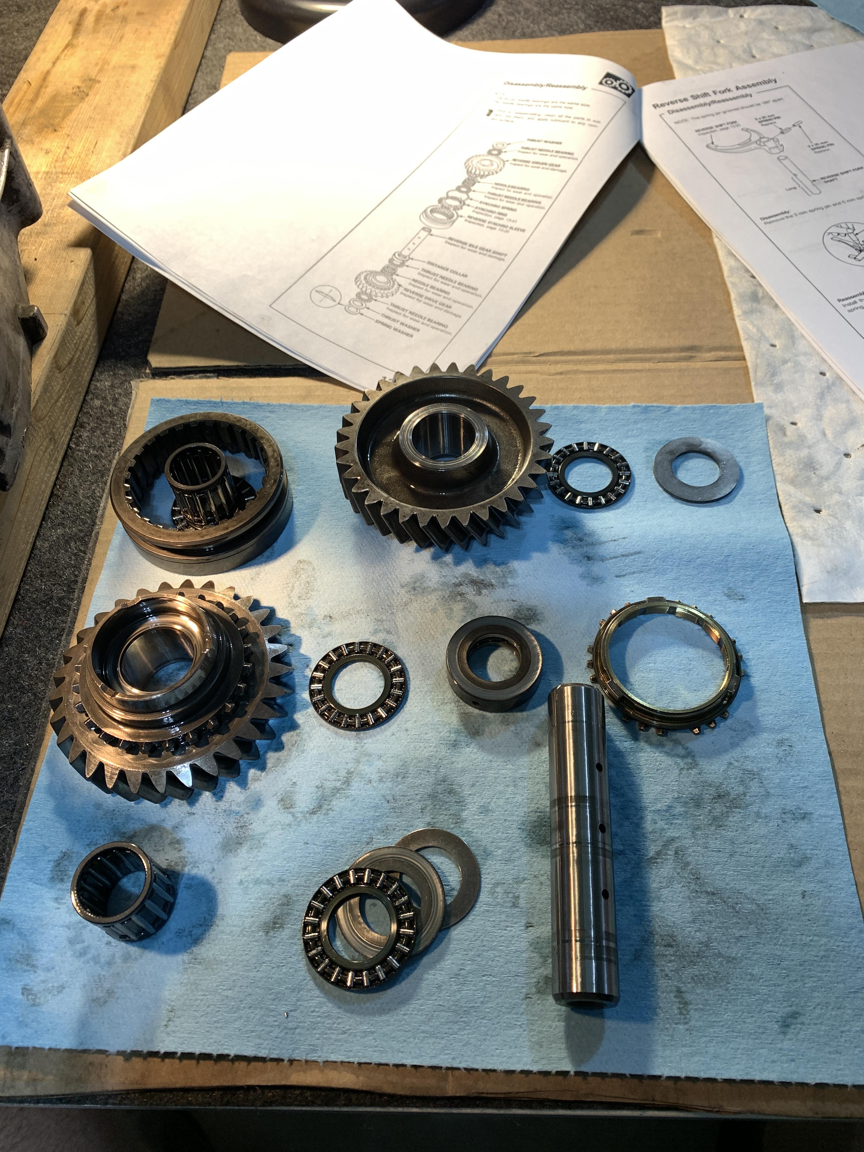
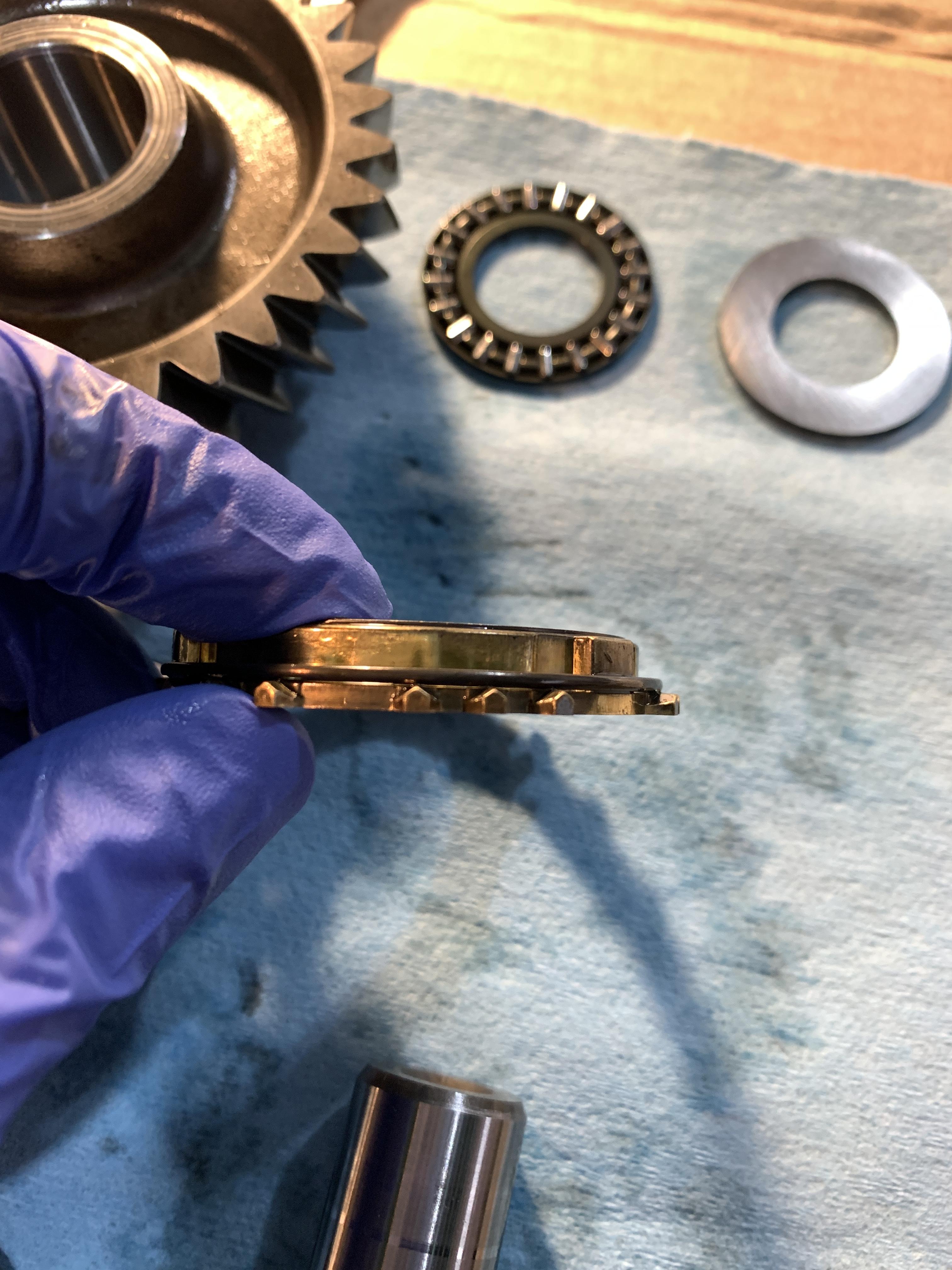
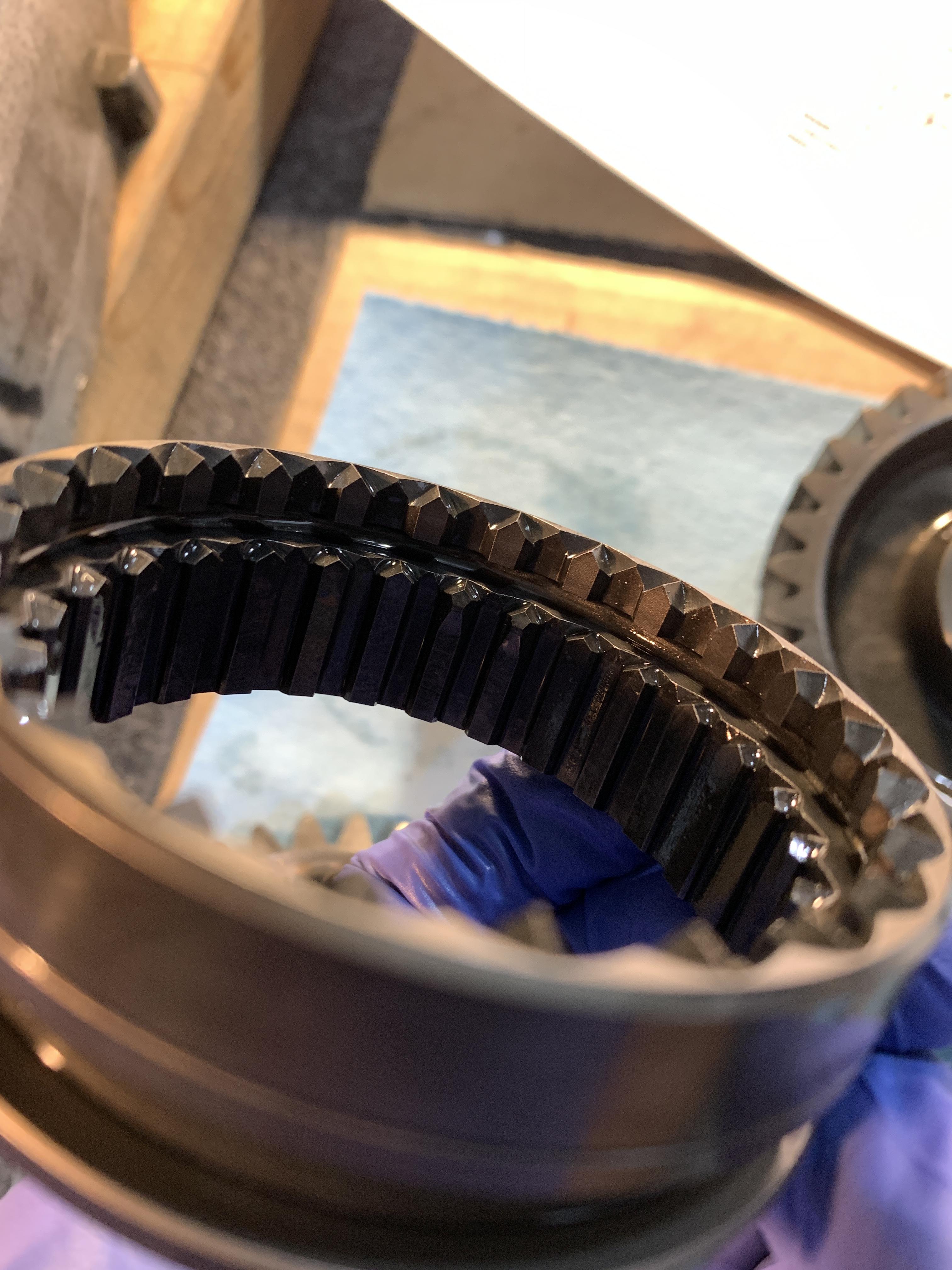
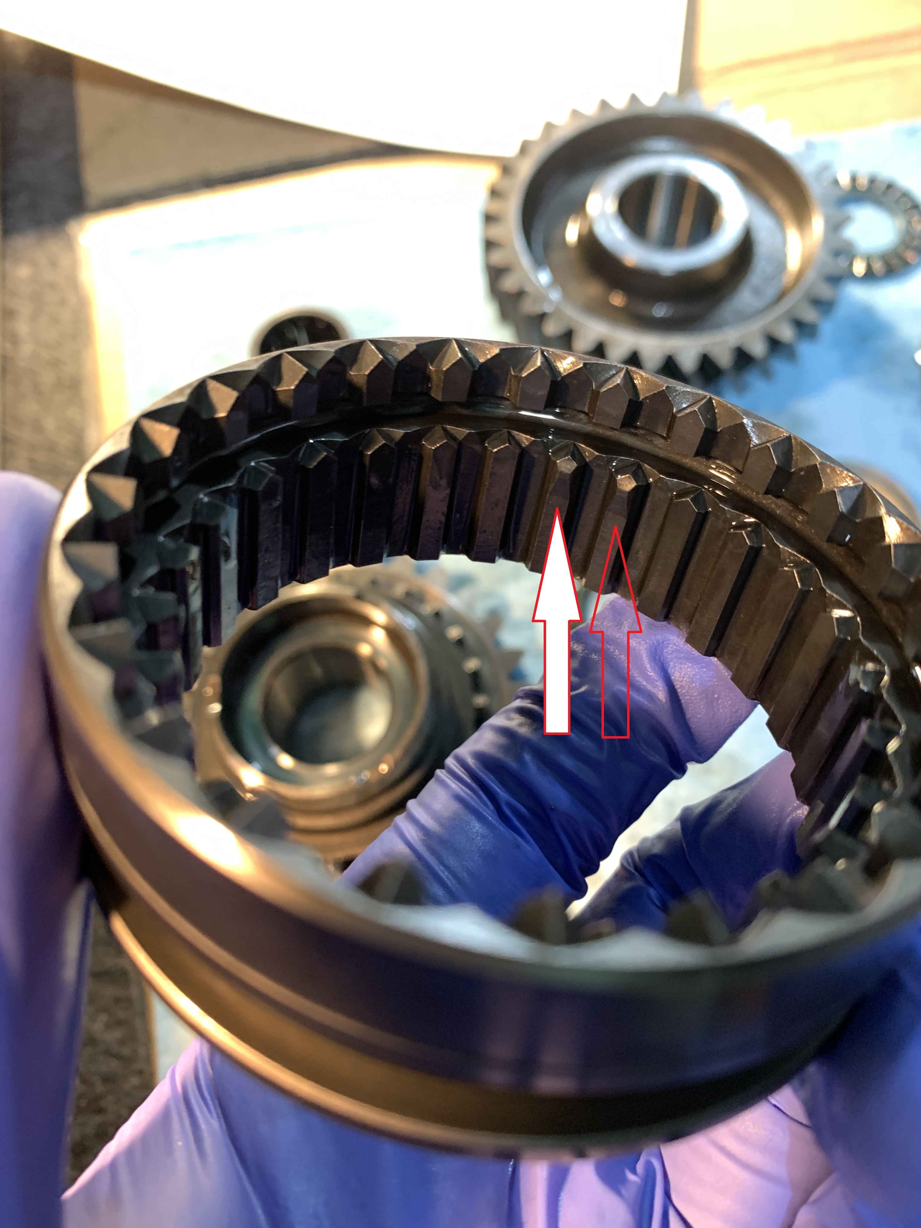
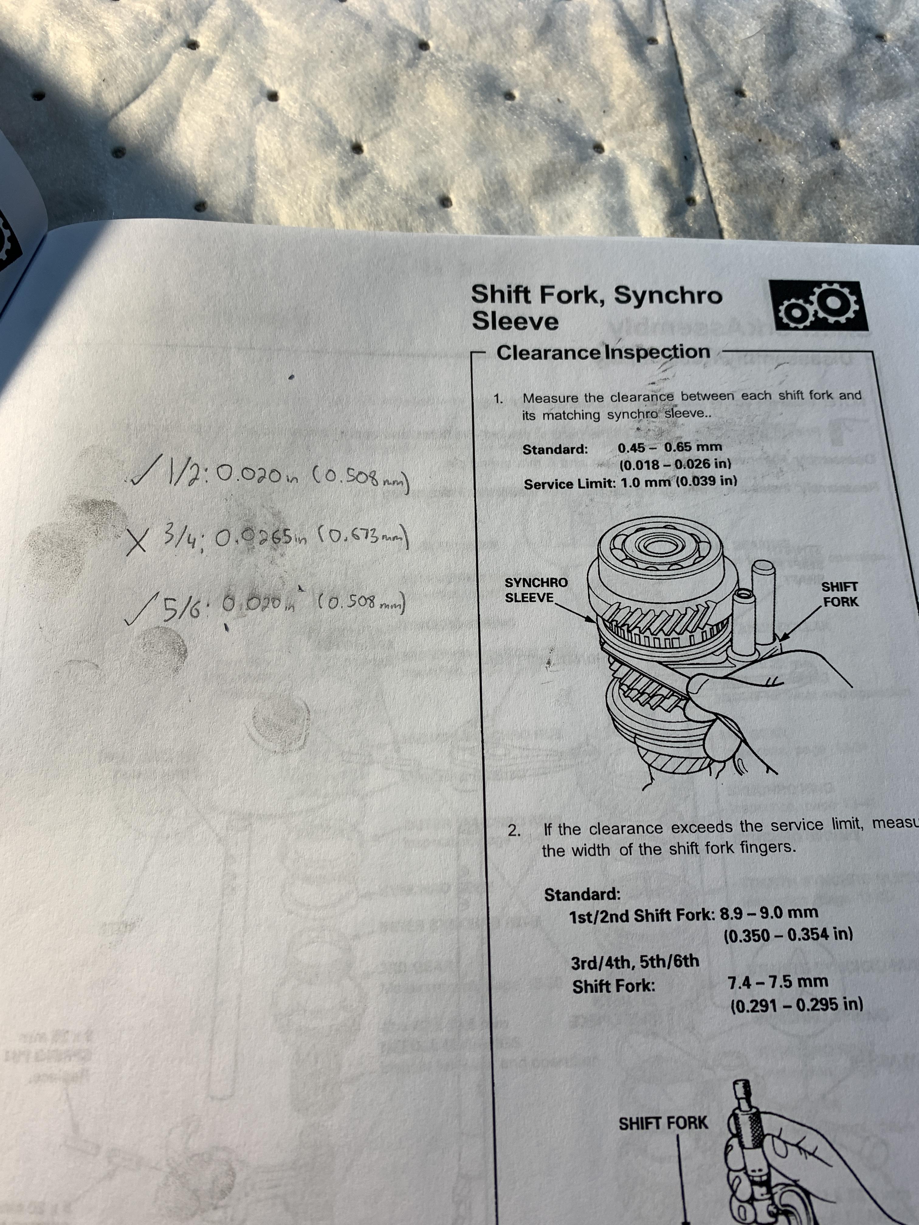
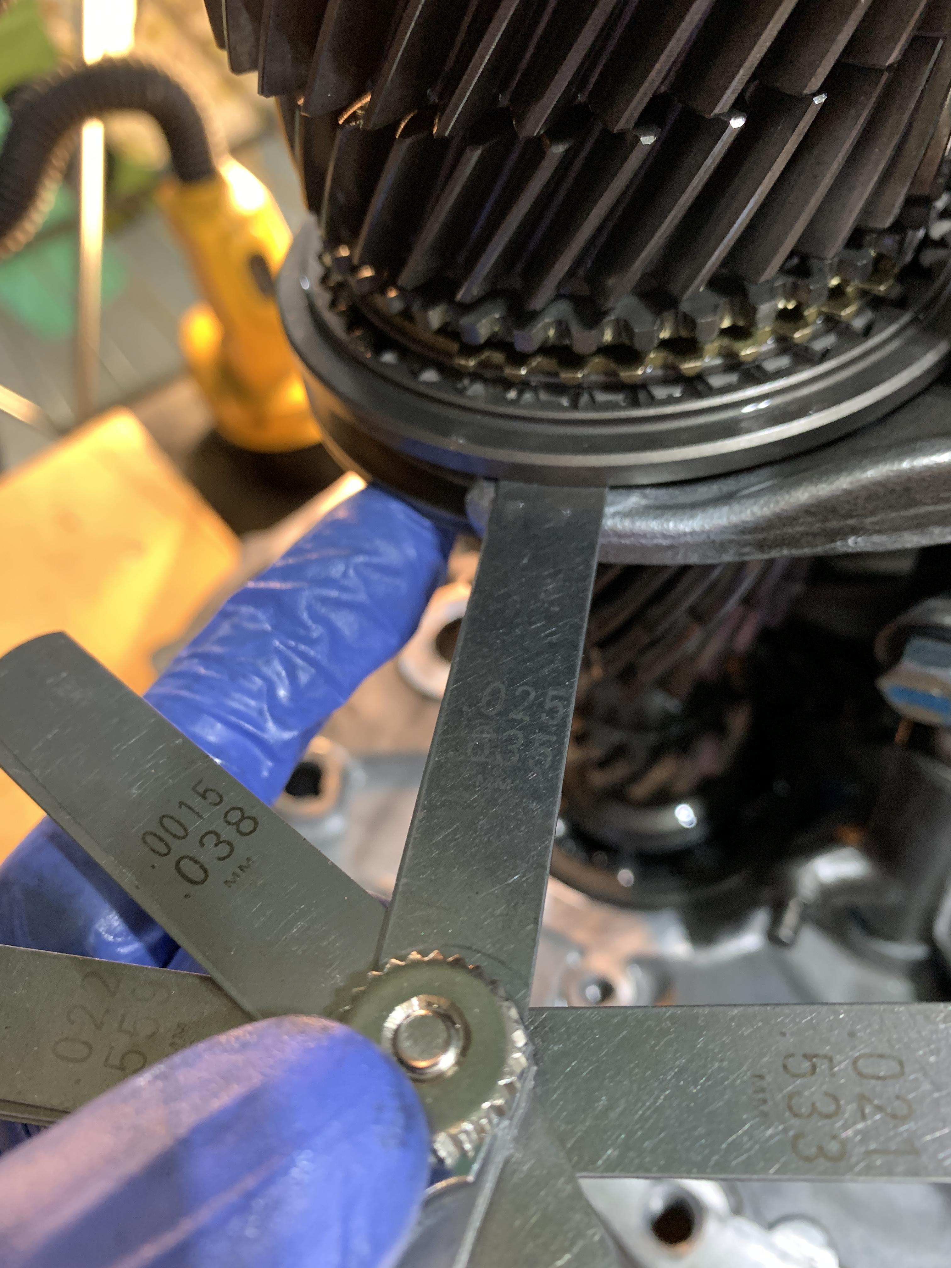
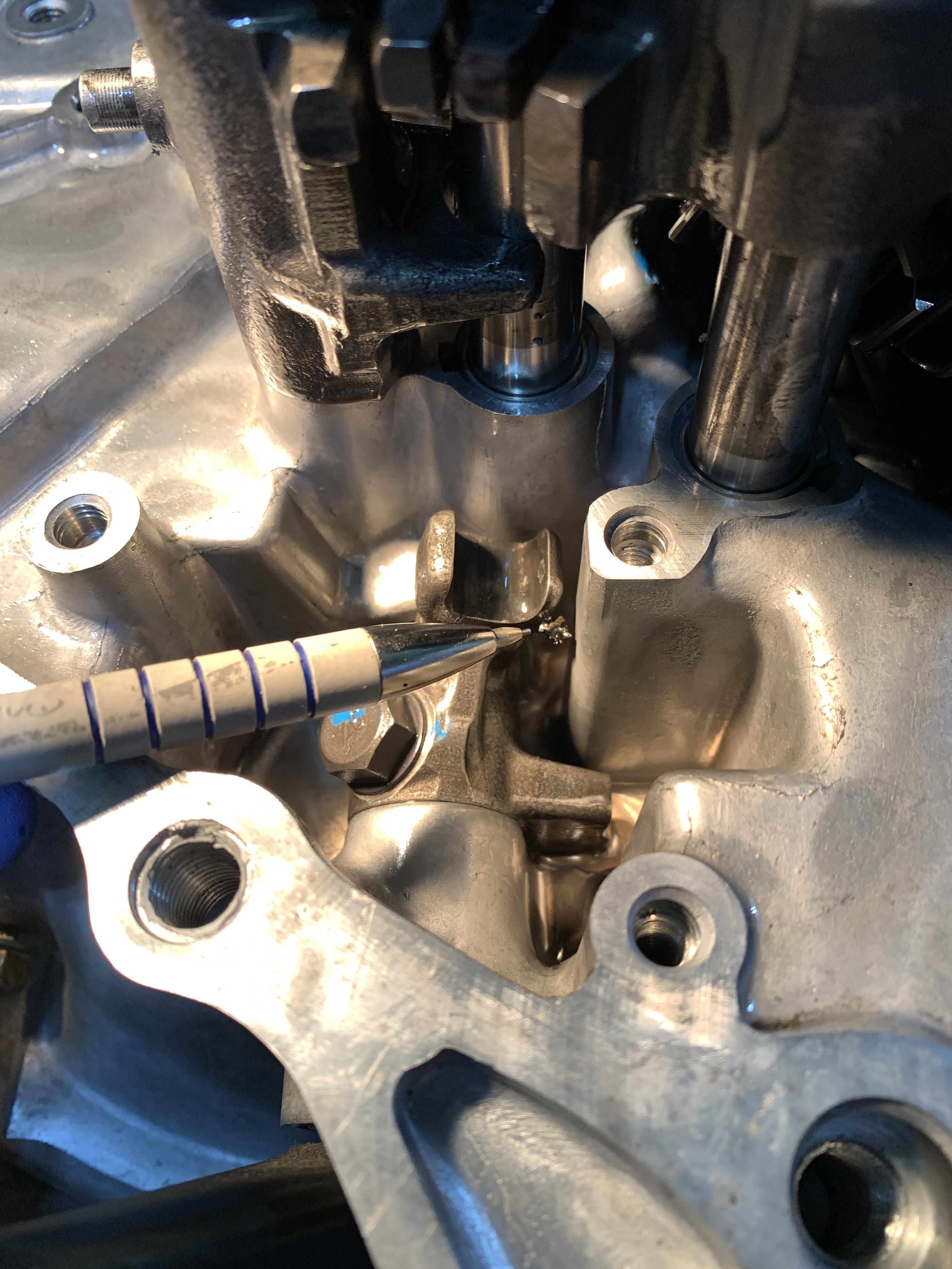
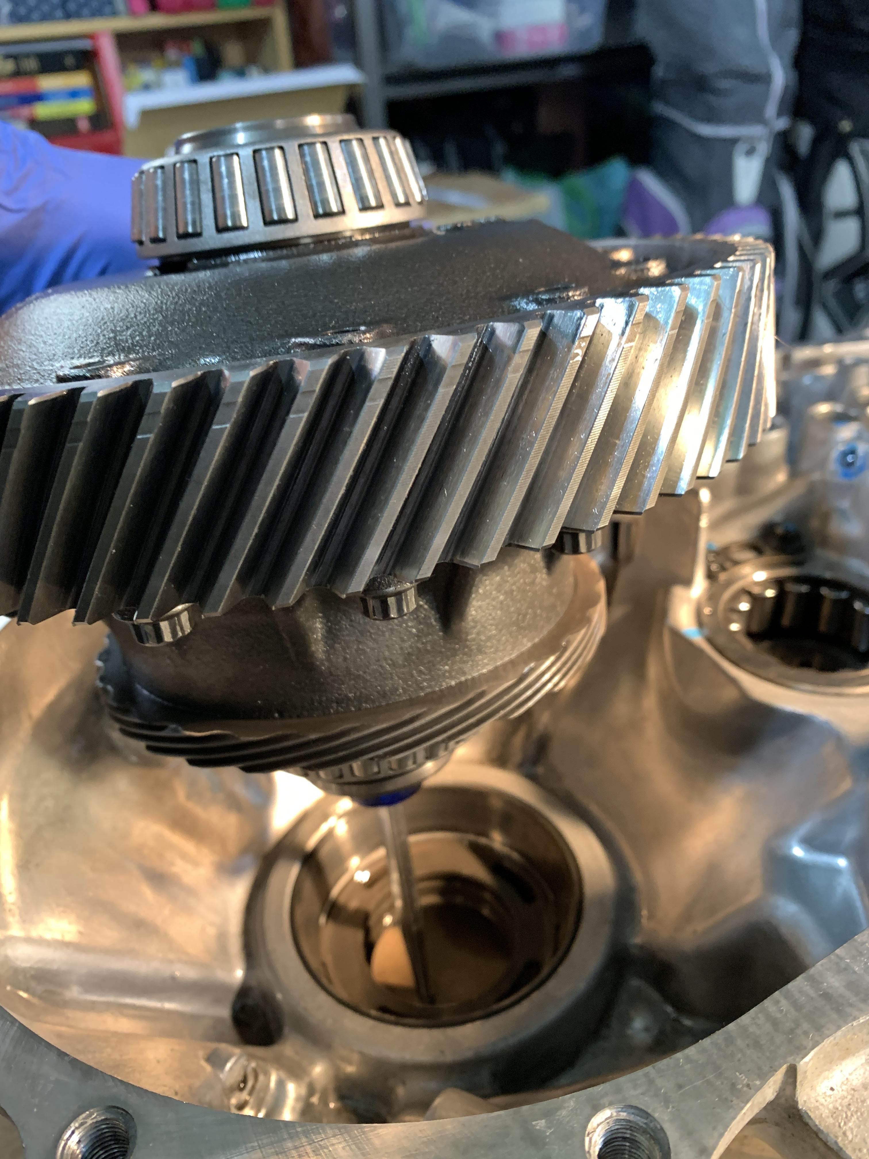
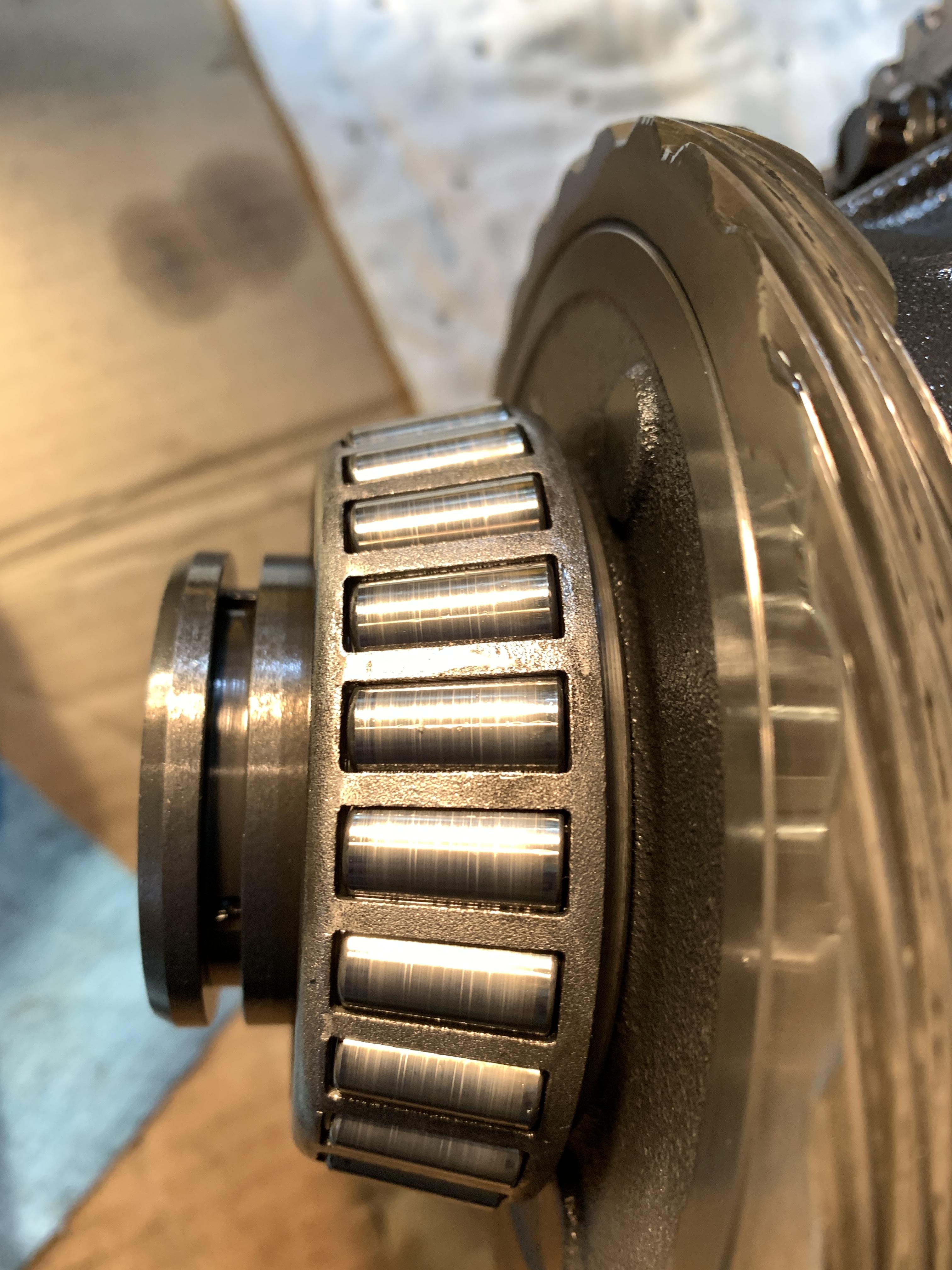
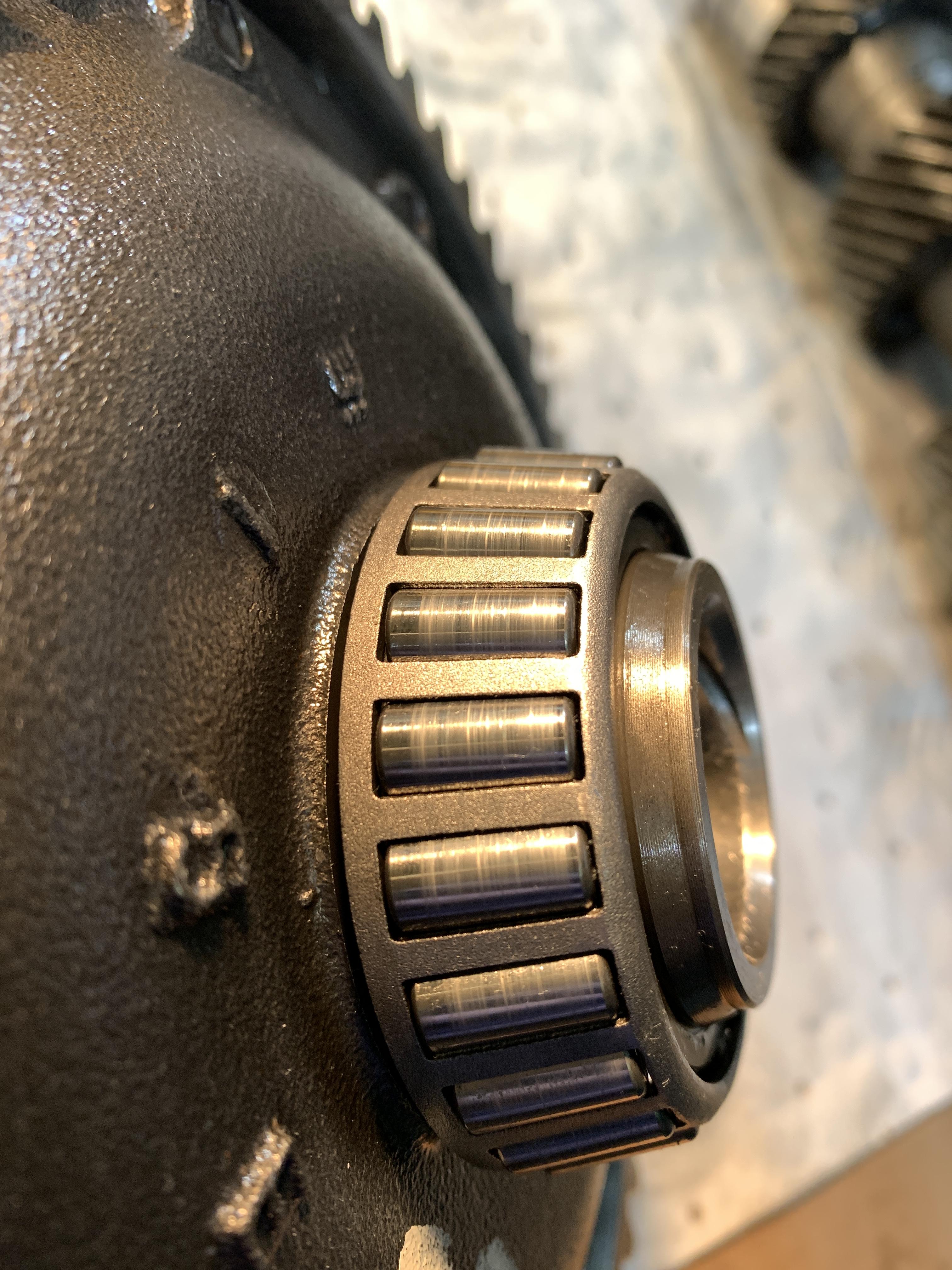
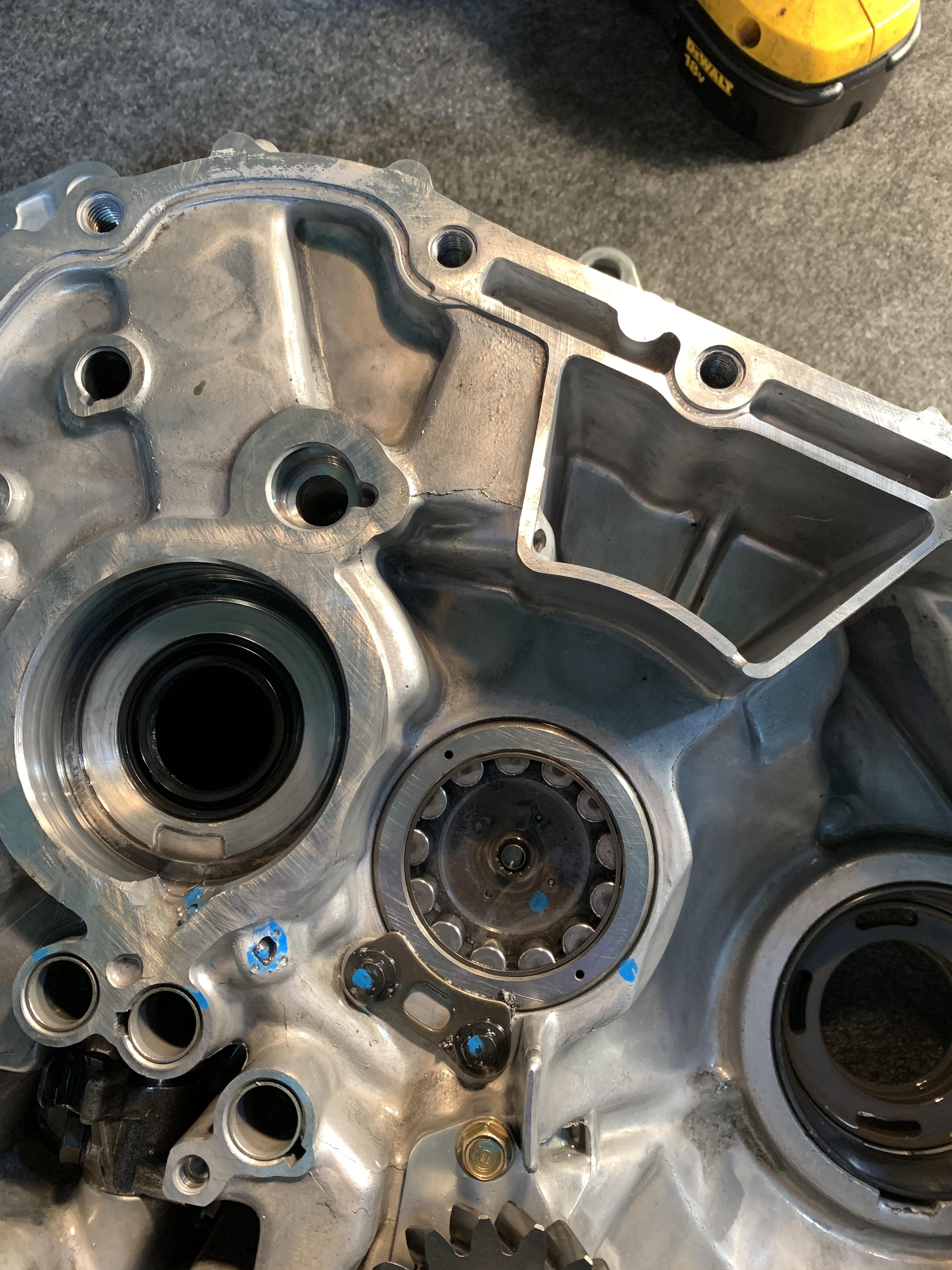
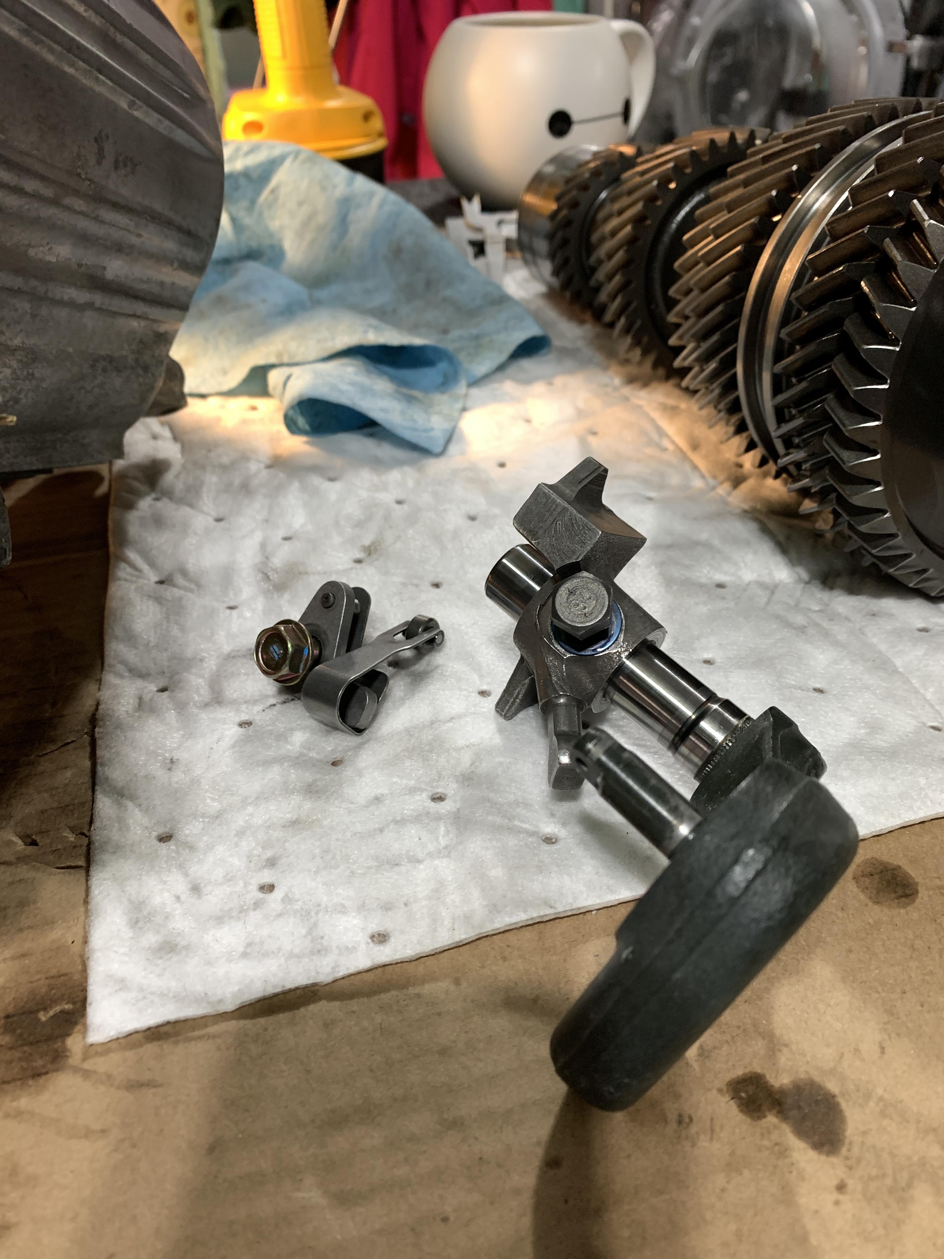
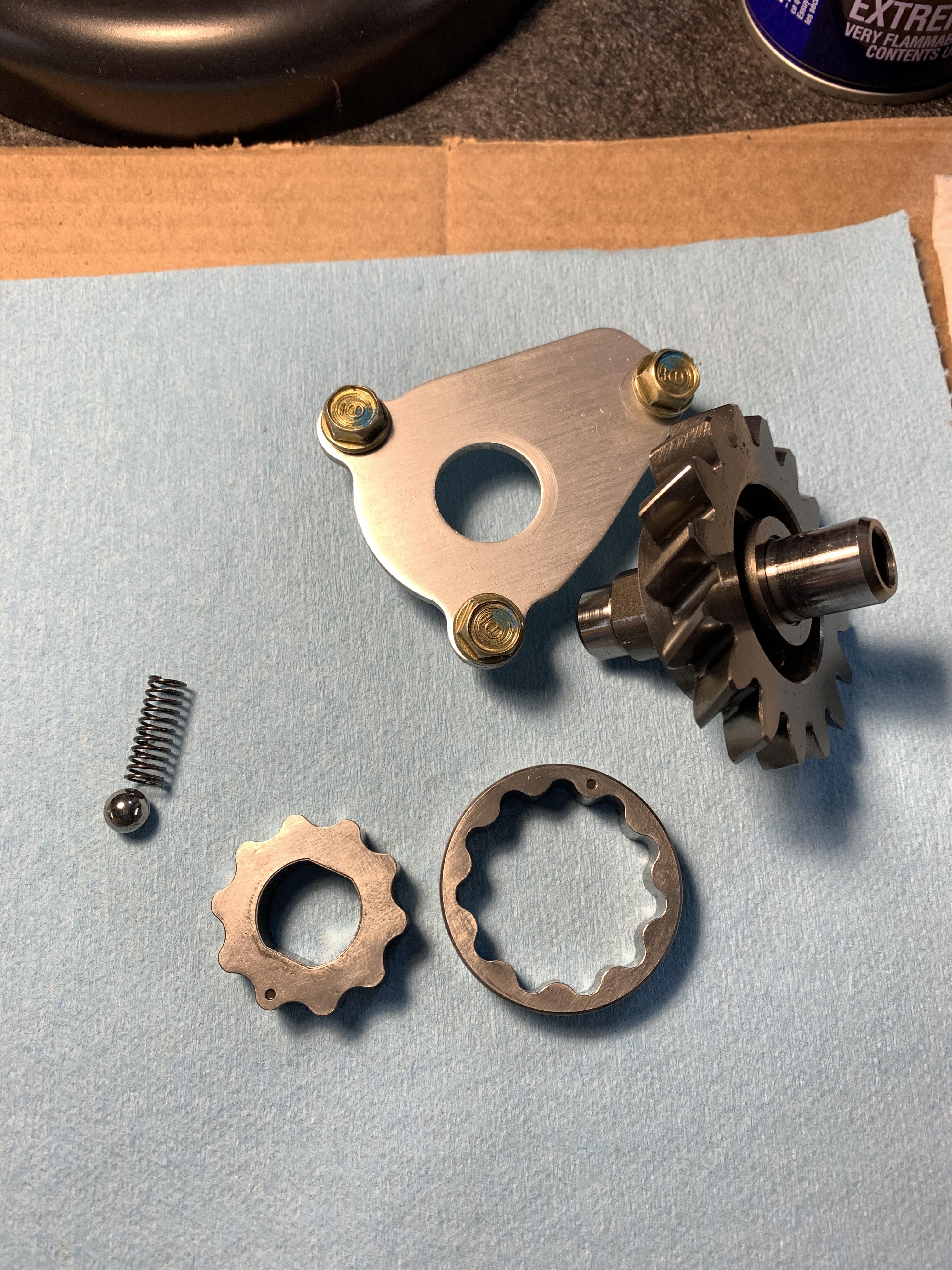
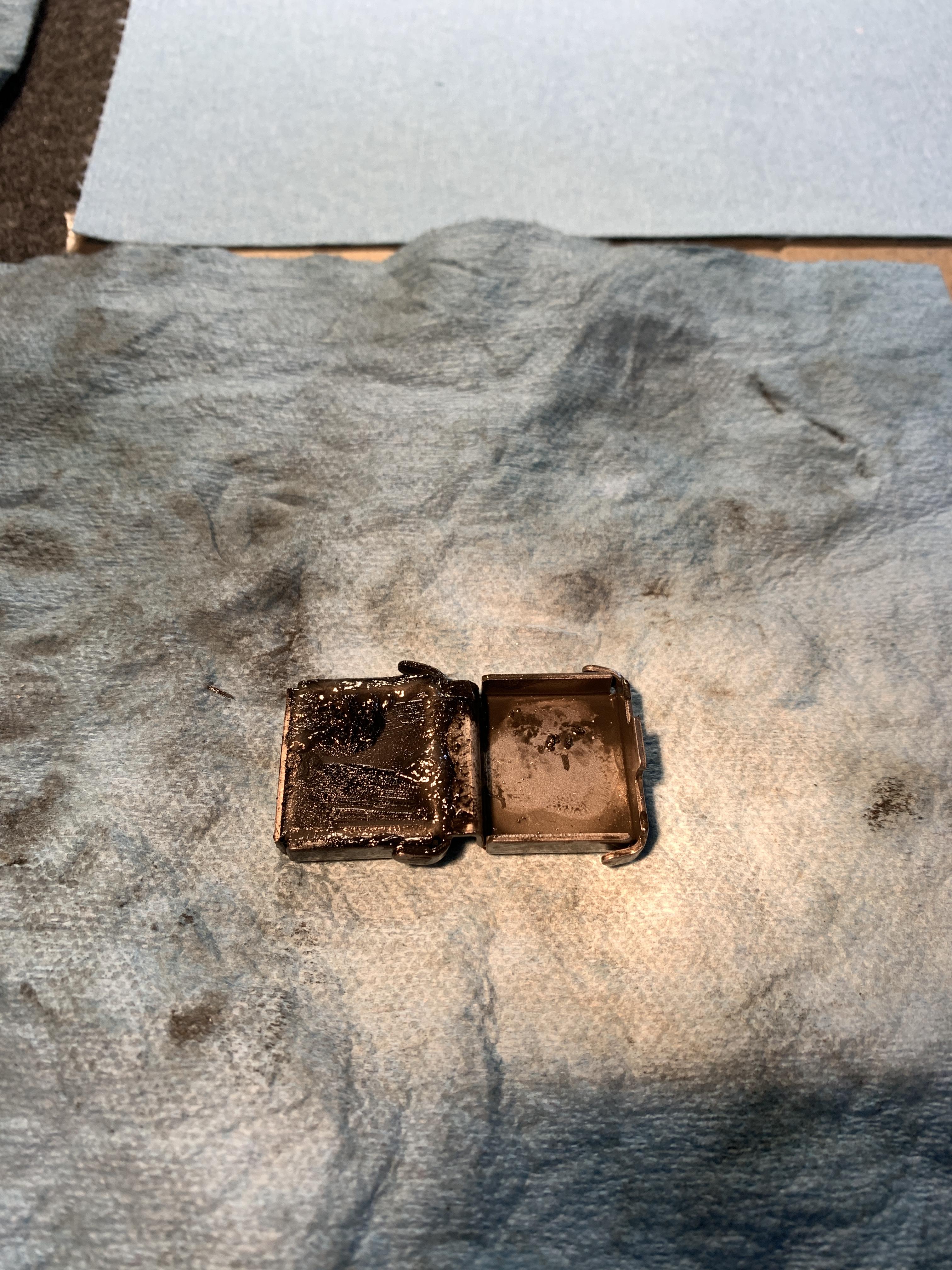
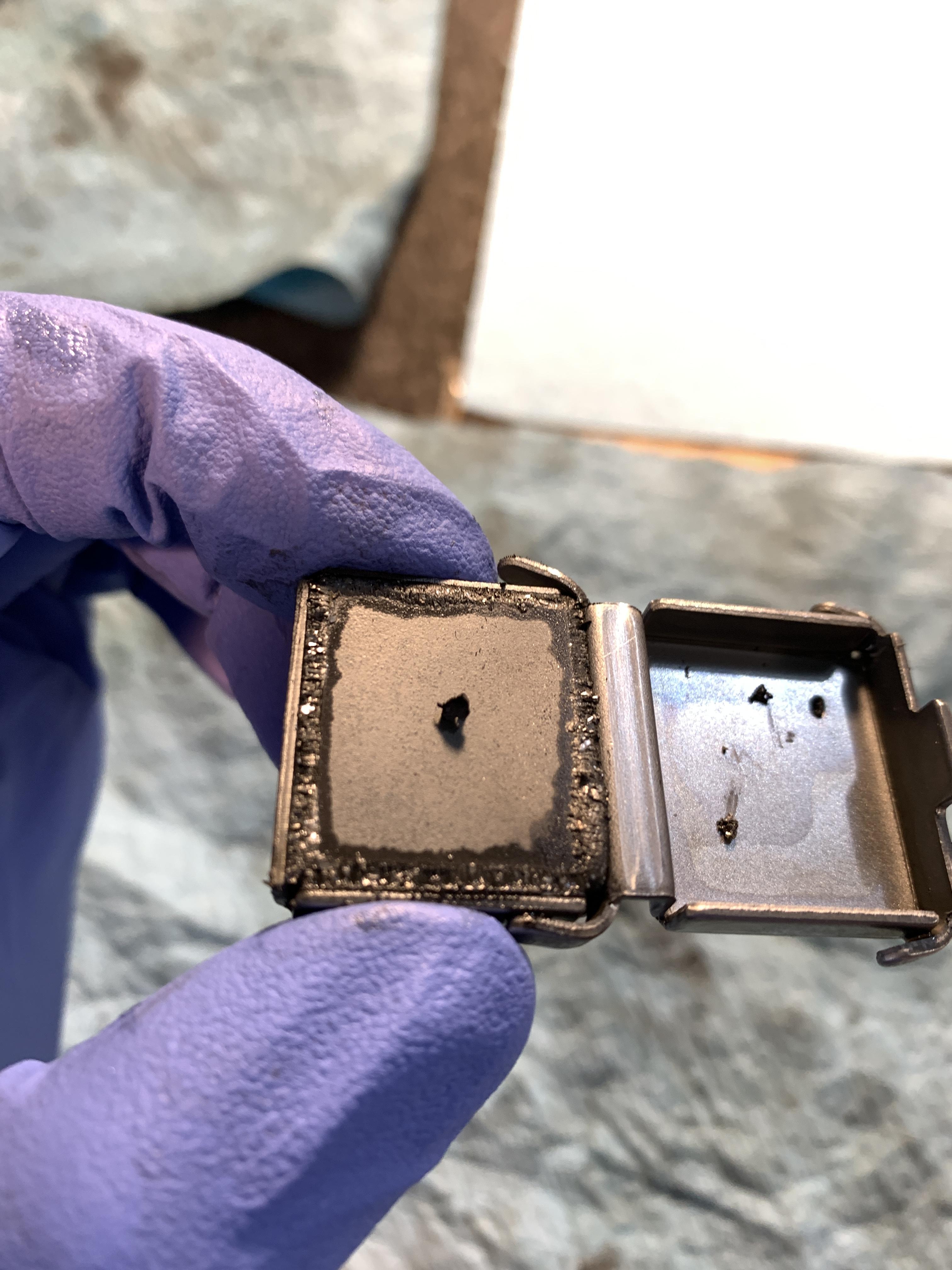
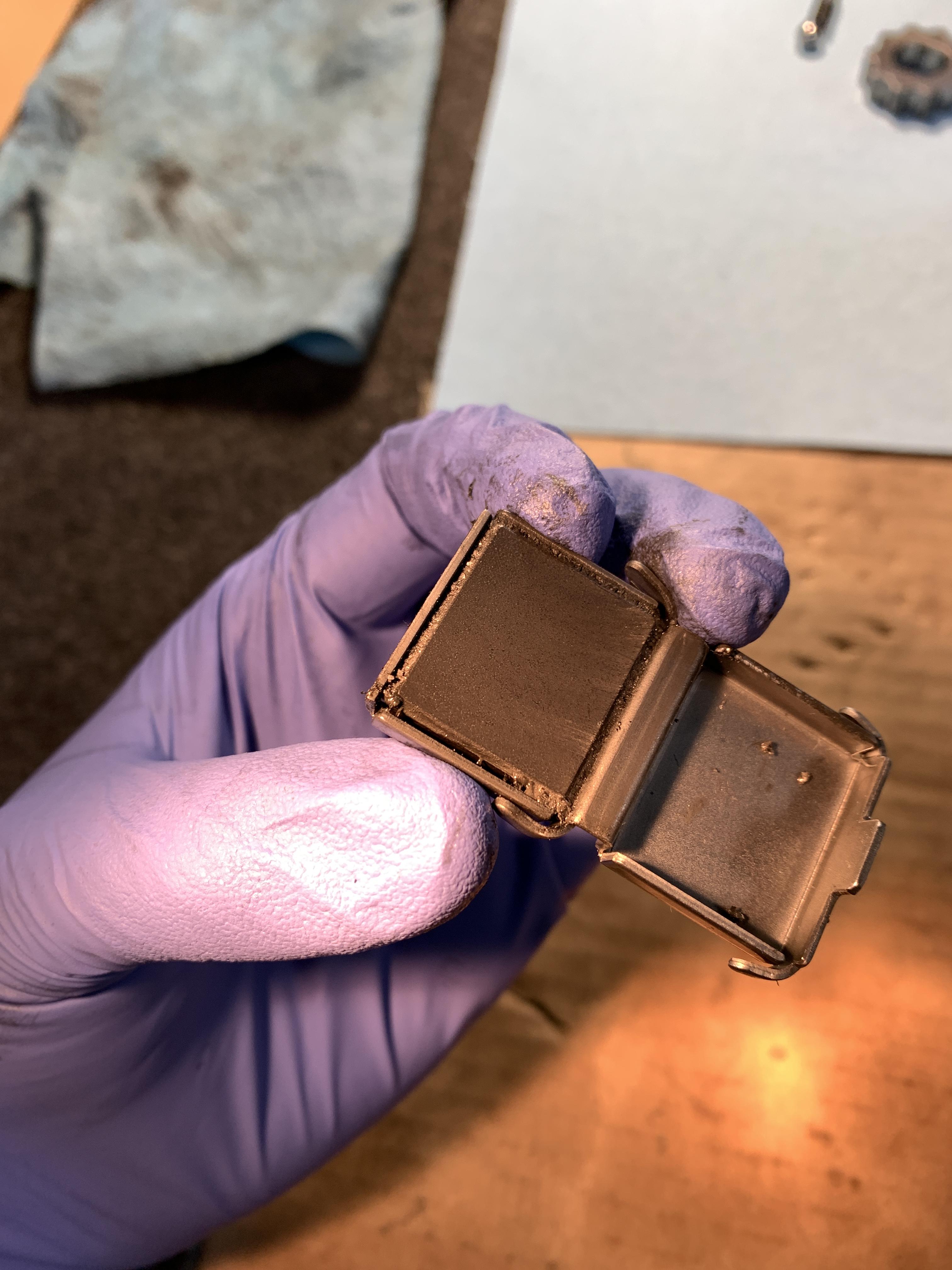
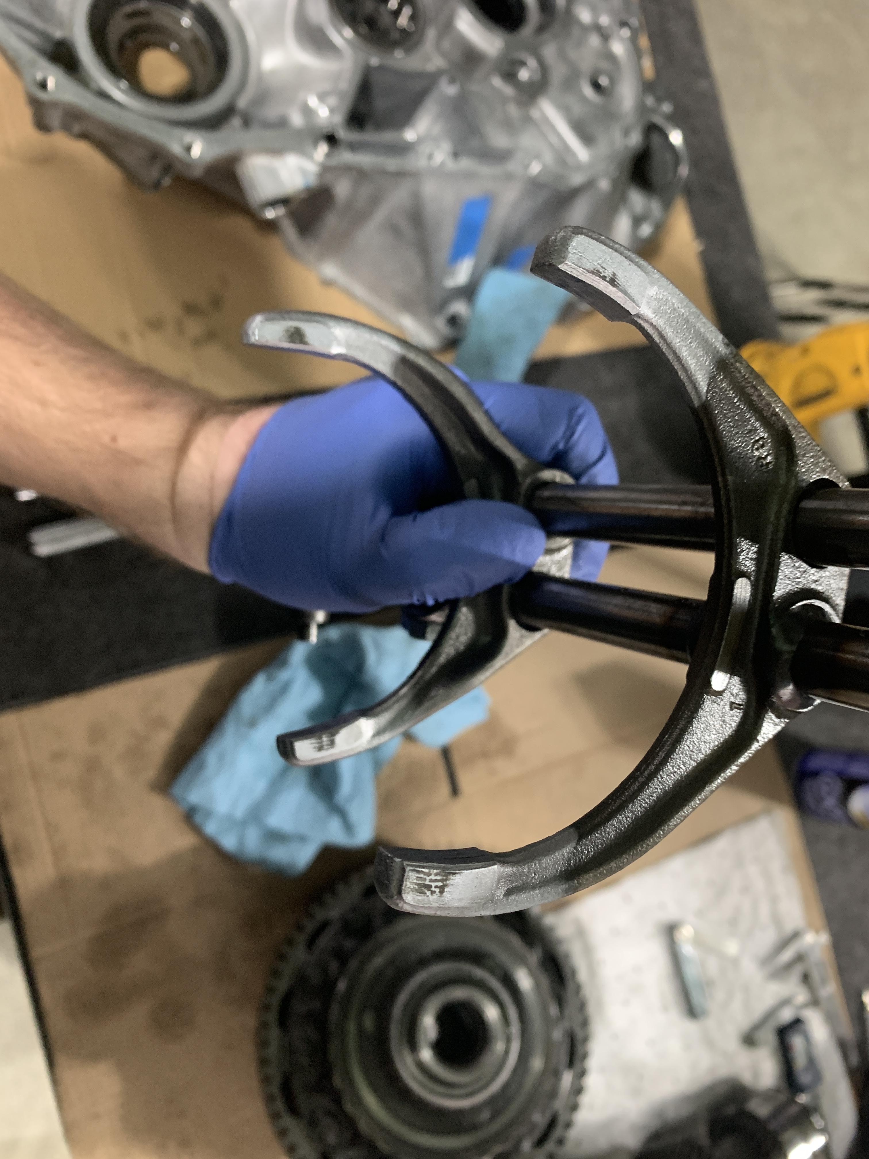
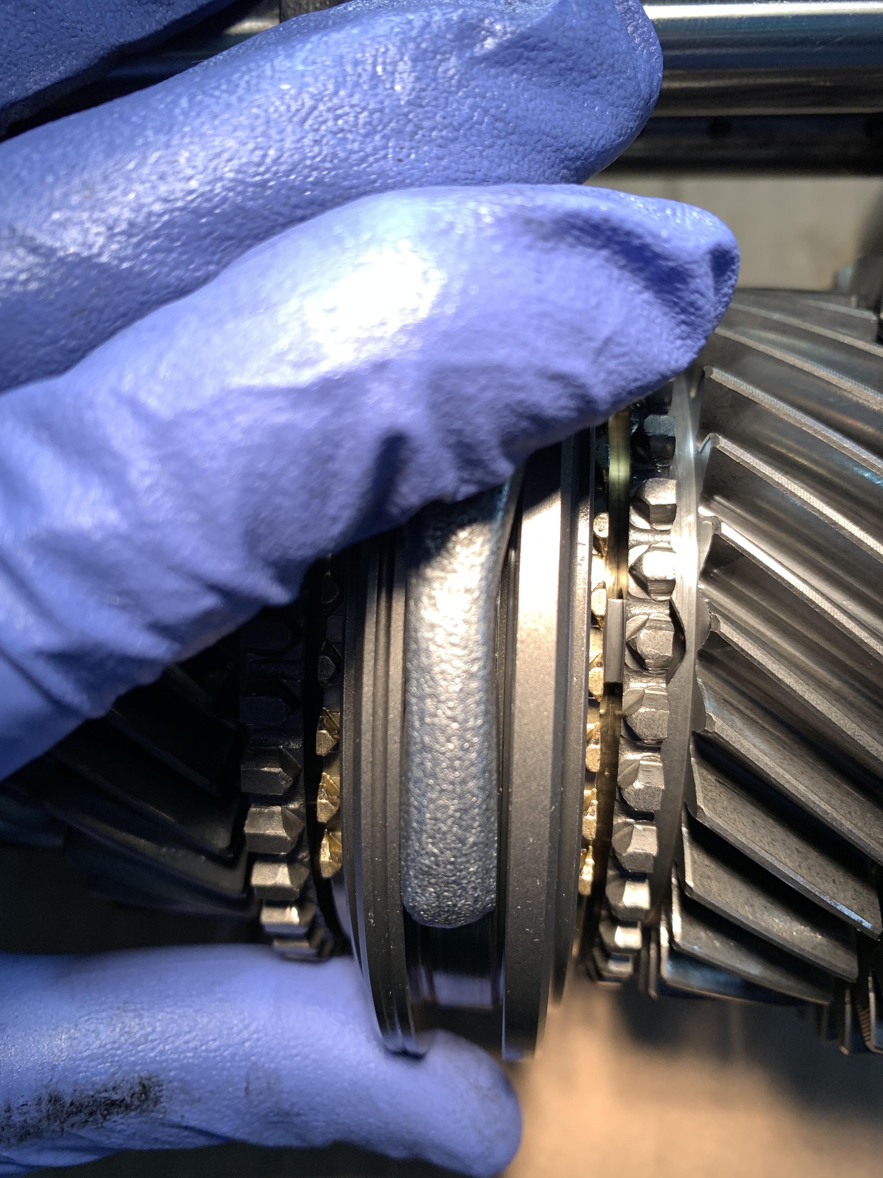
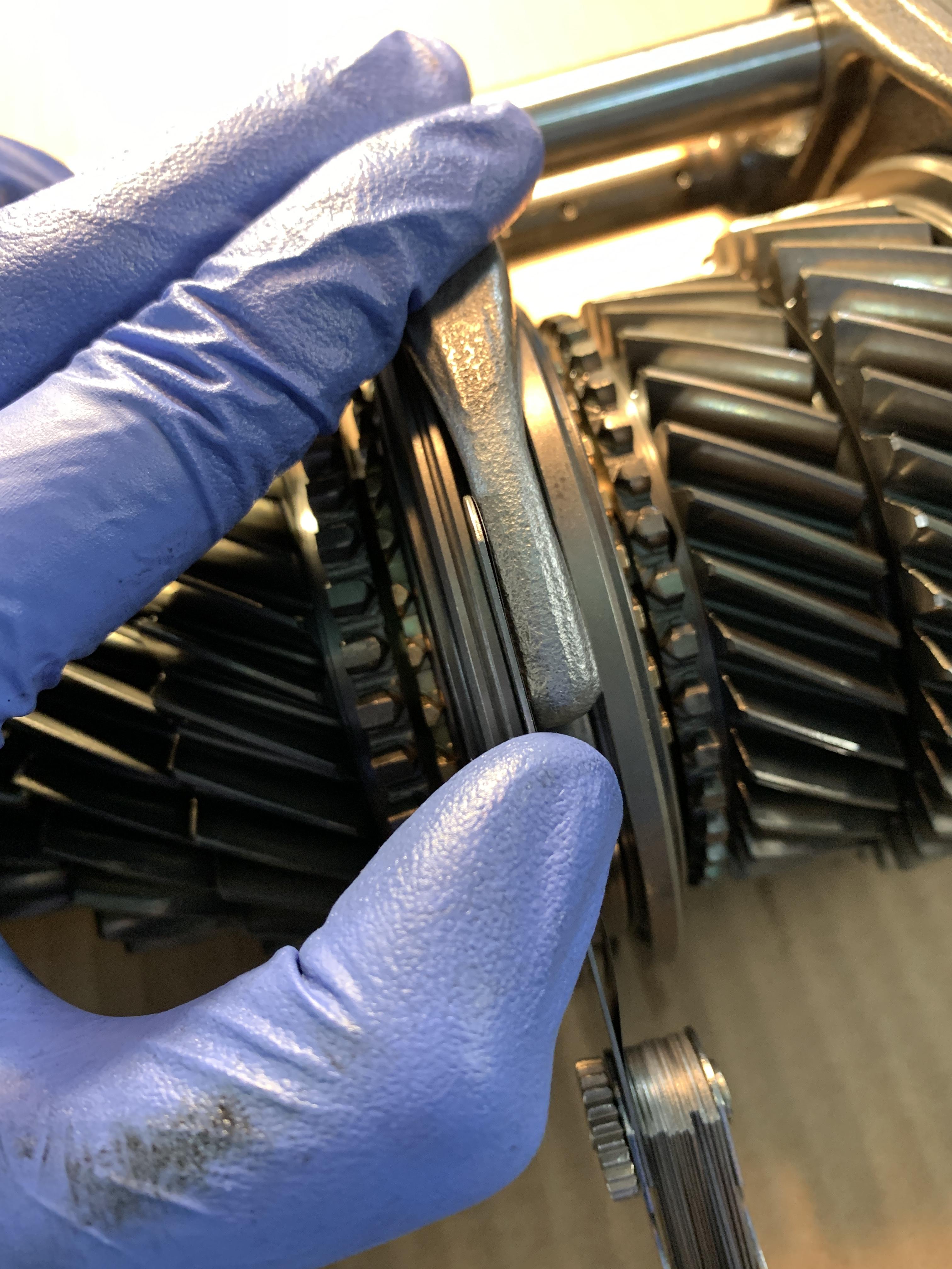
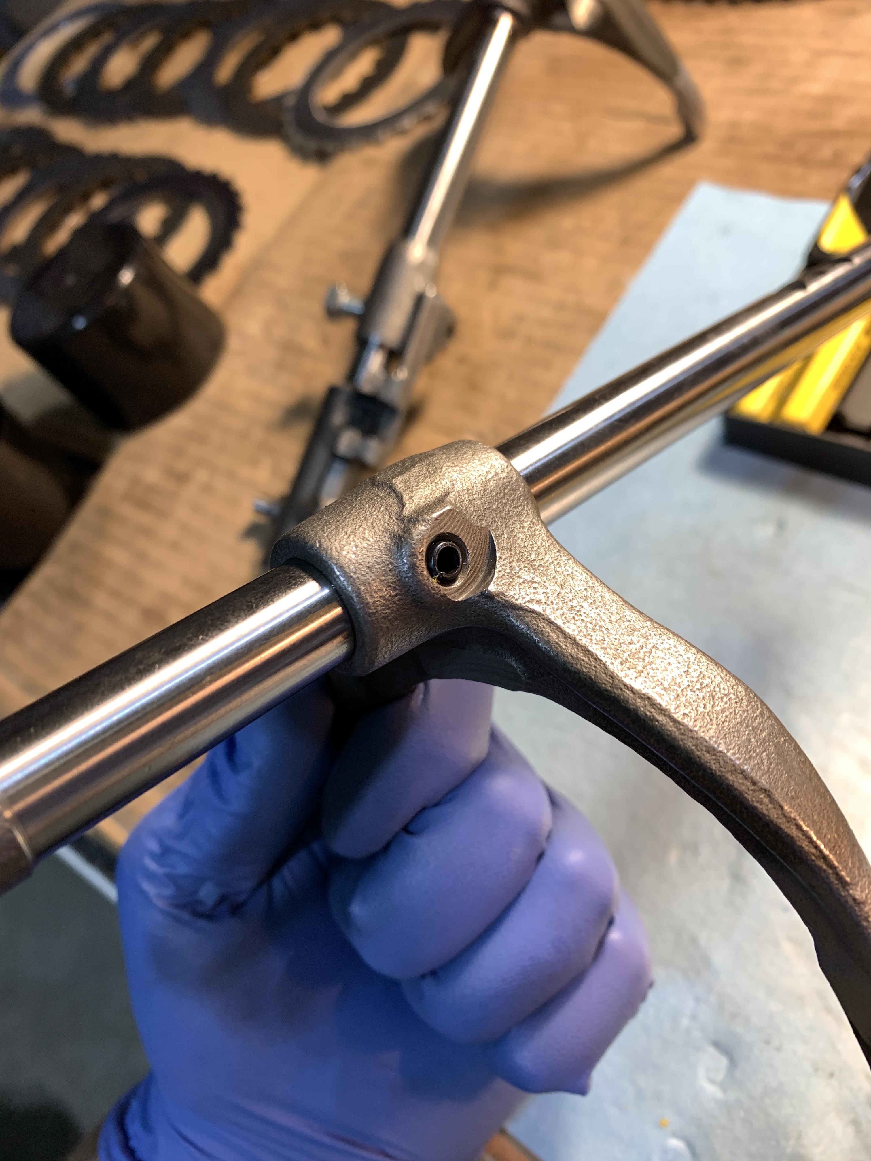
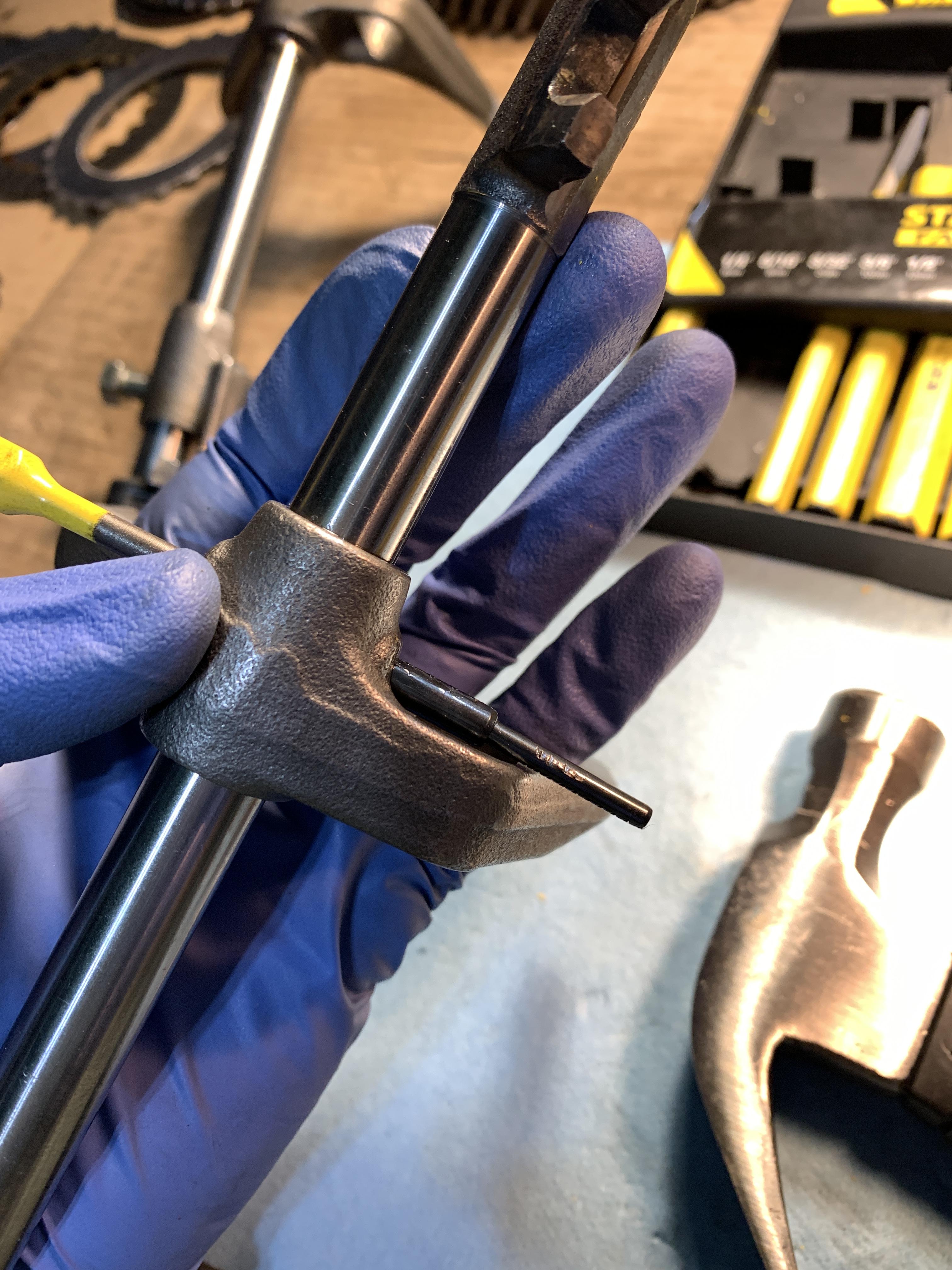
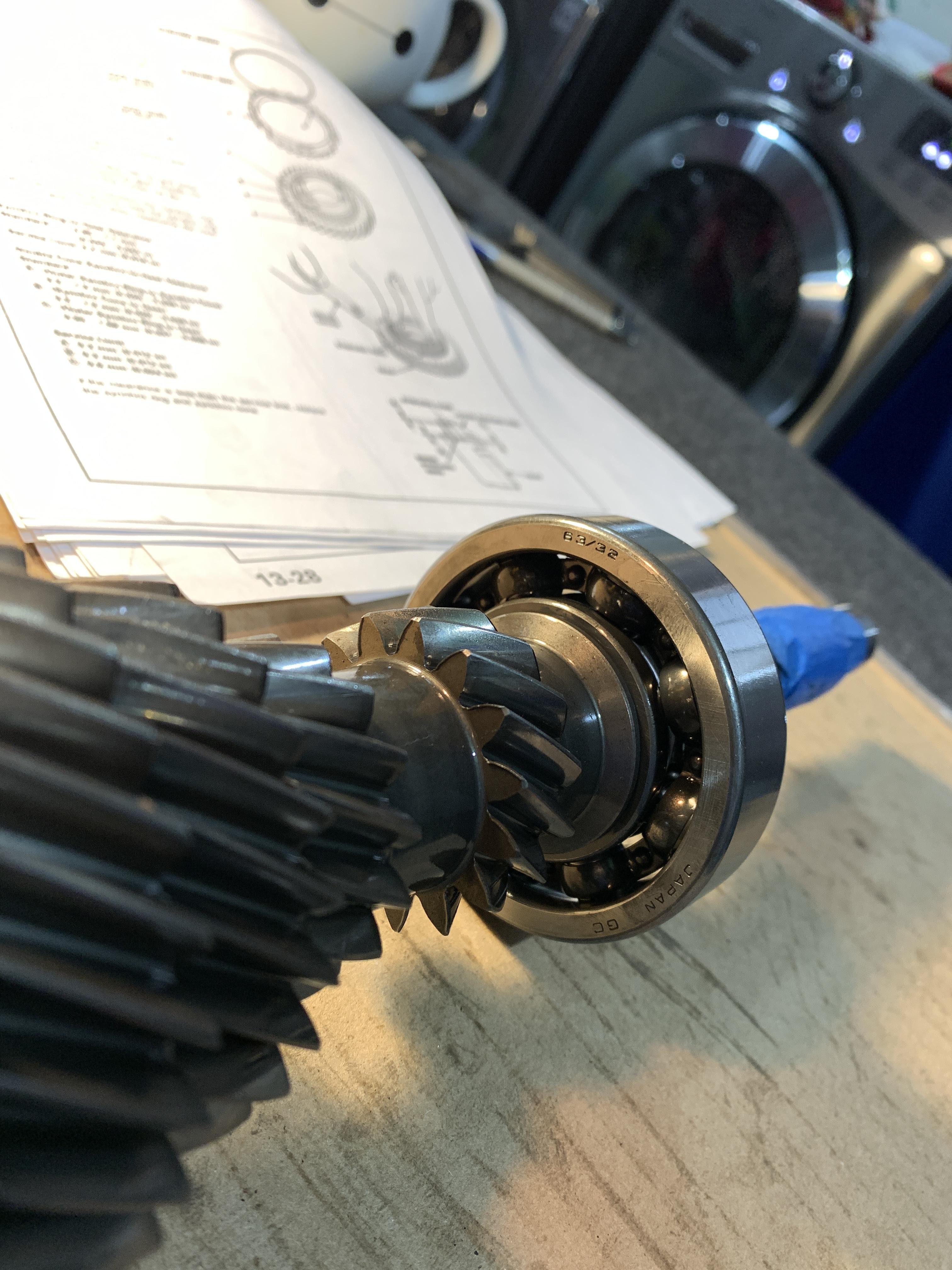
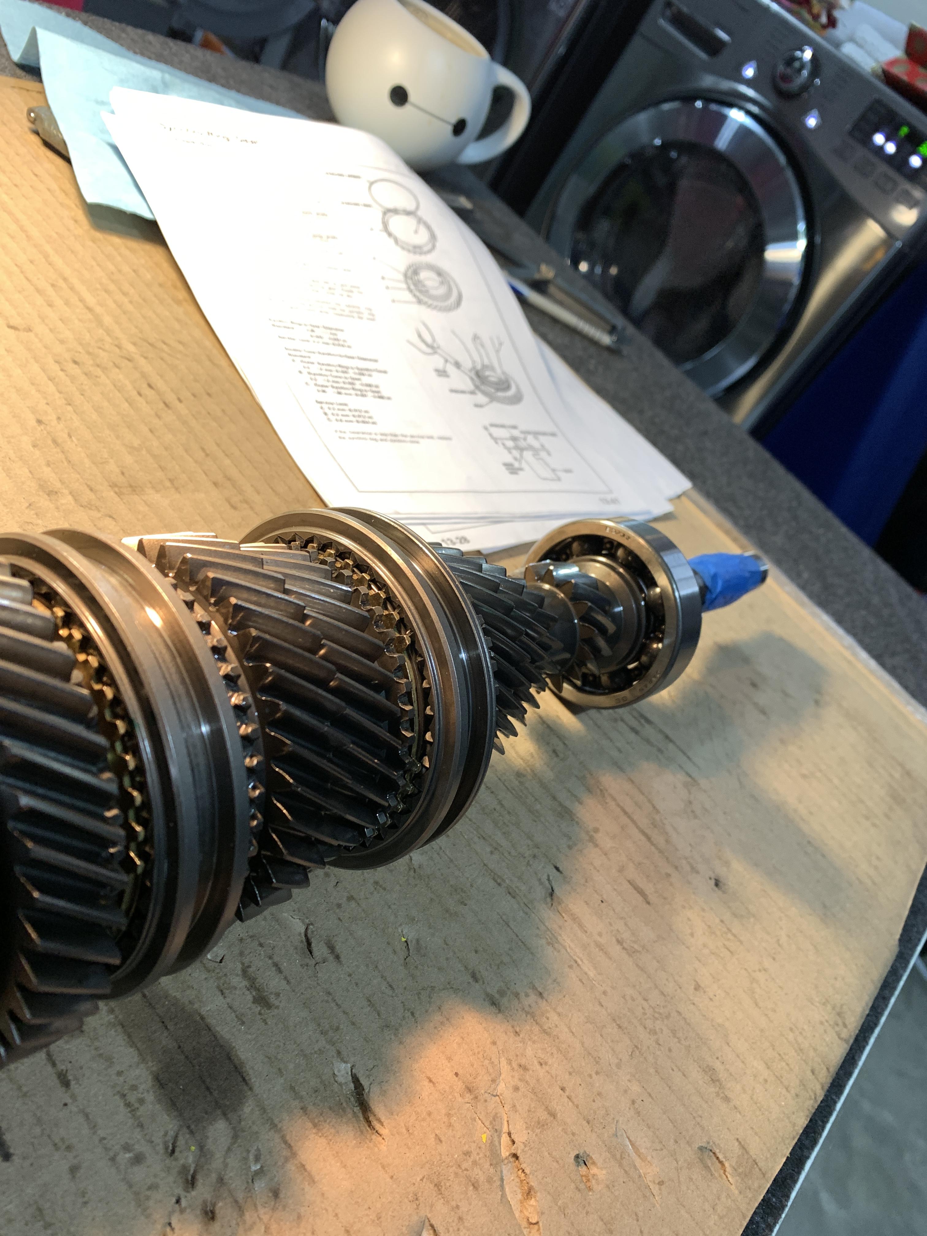
Also, there are so many "while you're in there" things I would consider. However, I also know how quickly the price ramps up and you get to a point of diminishing returns per dollar spent. BTW.. I just spent a small fortune just for new OEM 6spd parts like bearings, shims, etc... It's crazy how much all of that stuff adds up.

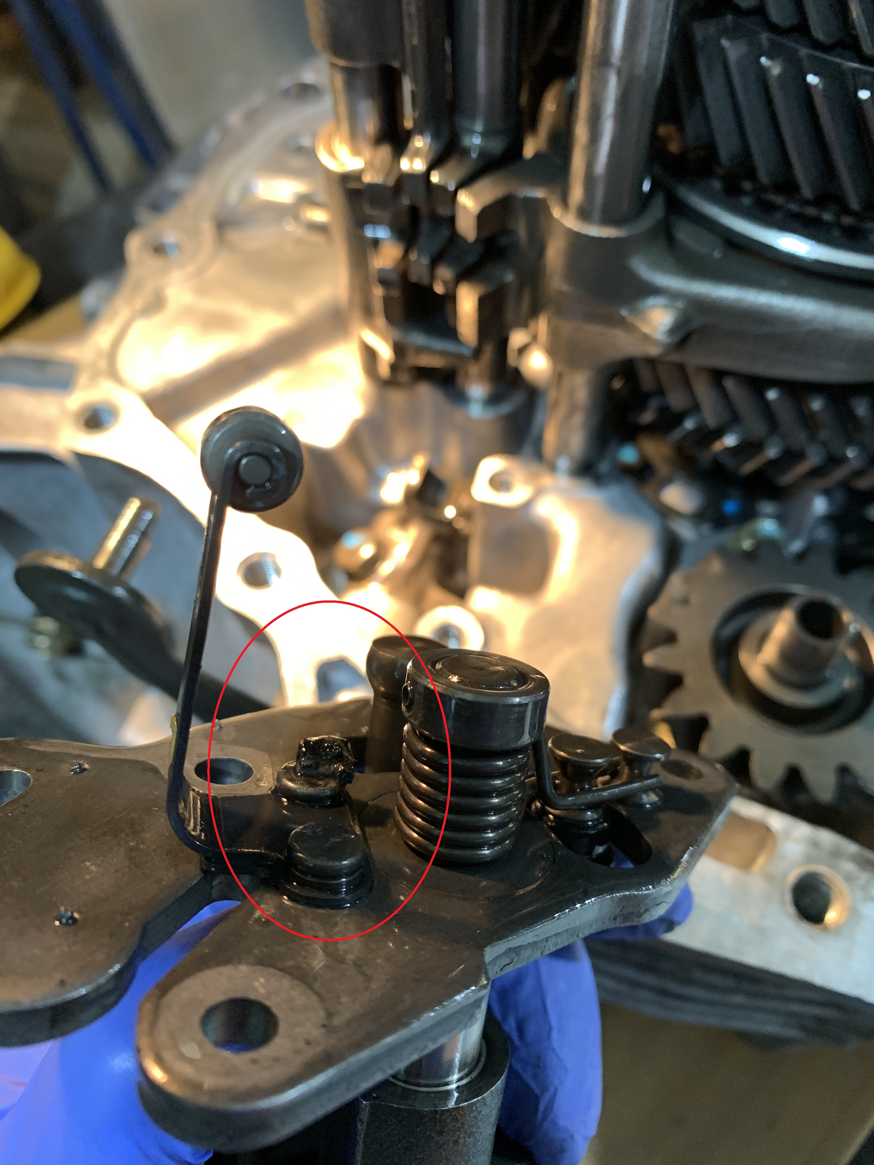
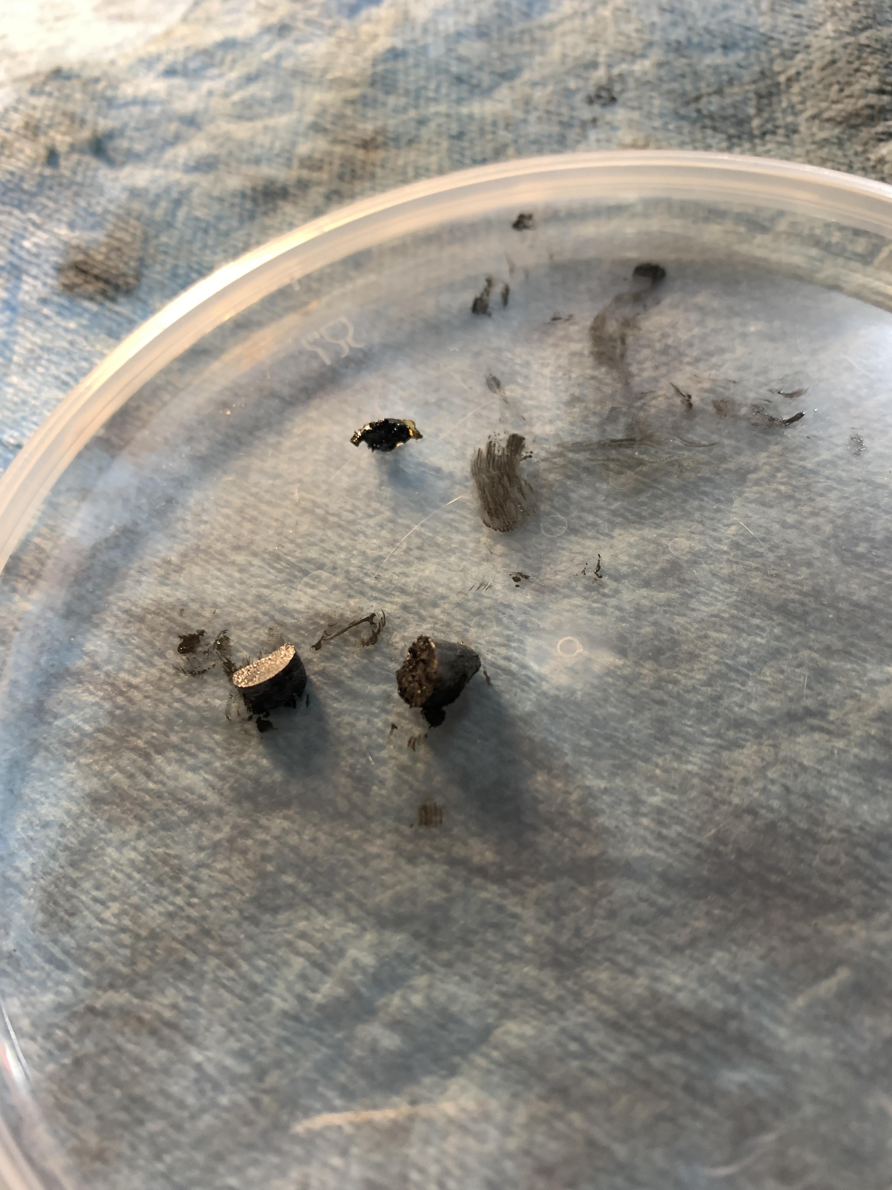
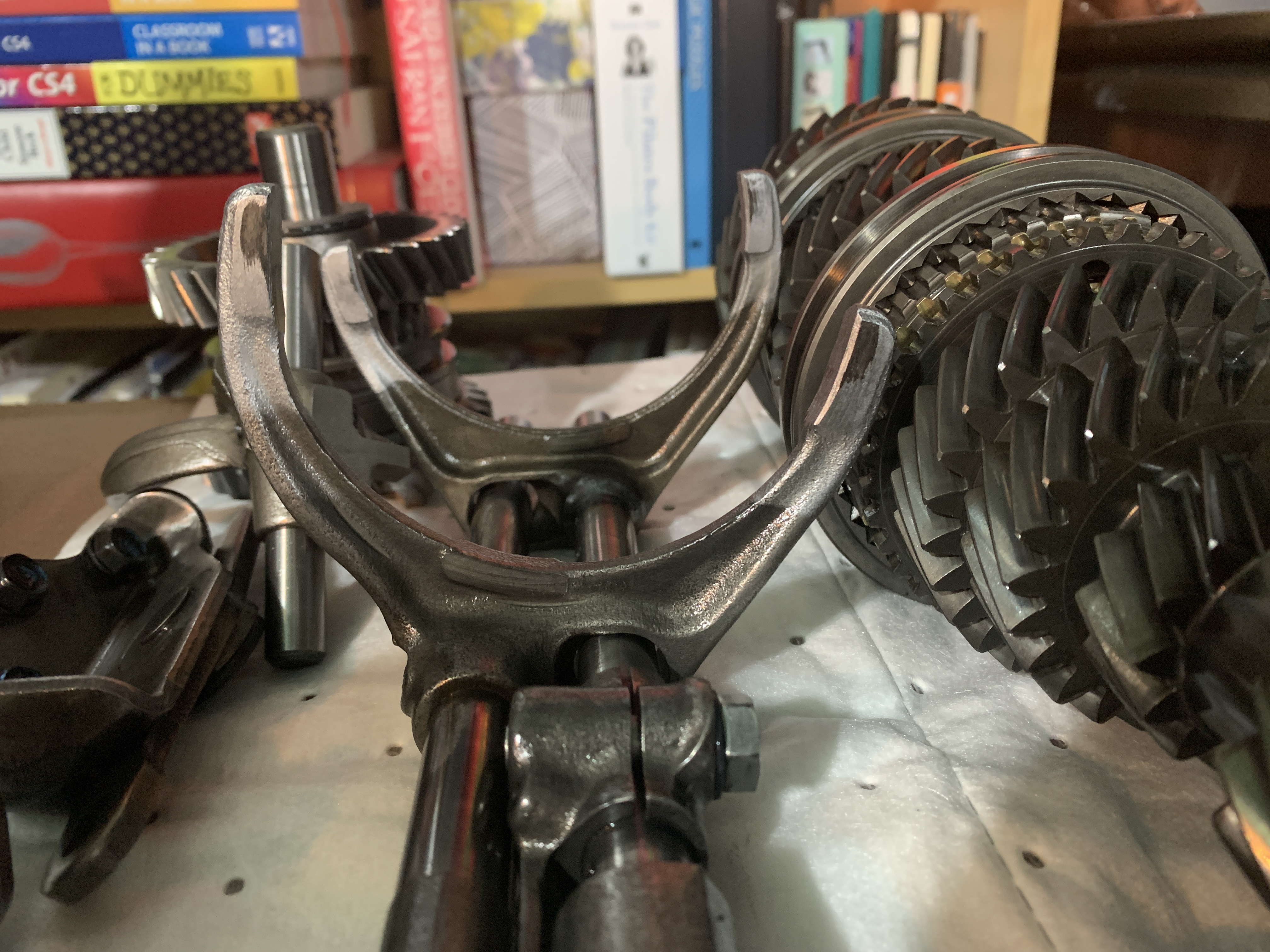
Some parts come to mind.
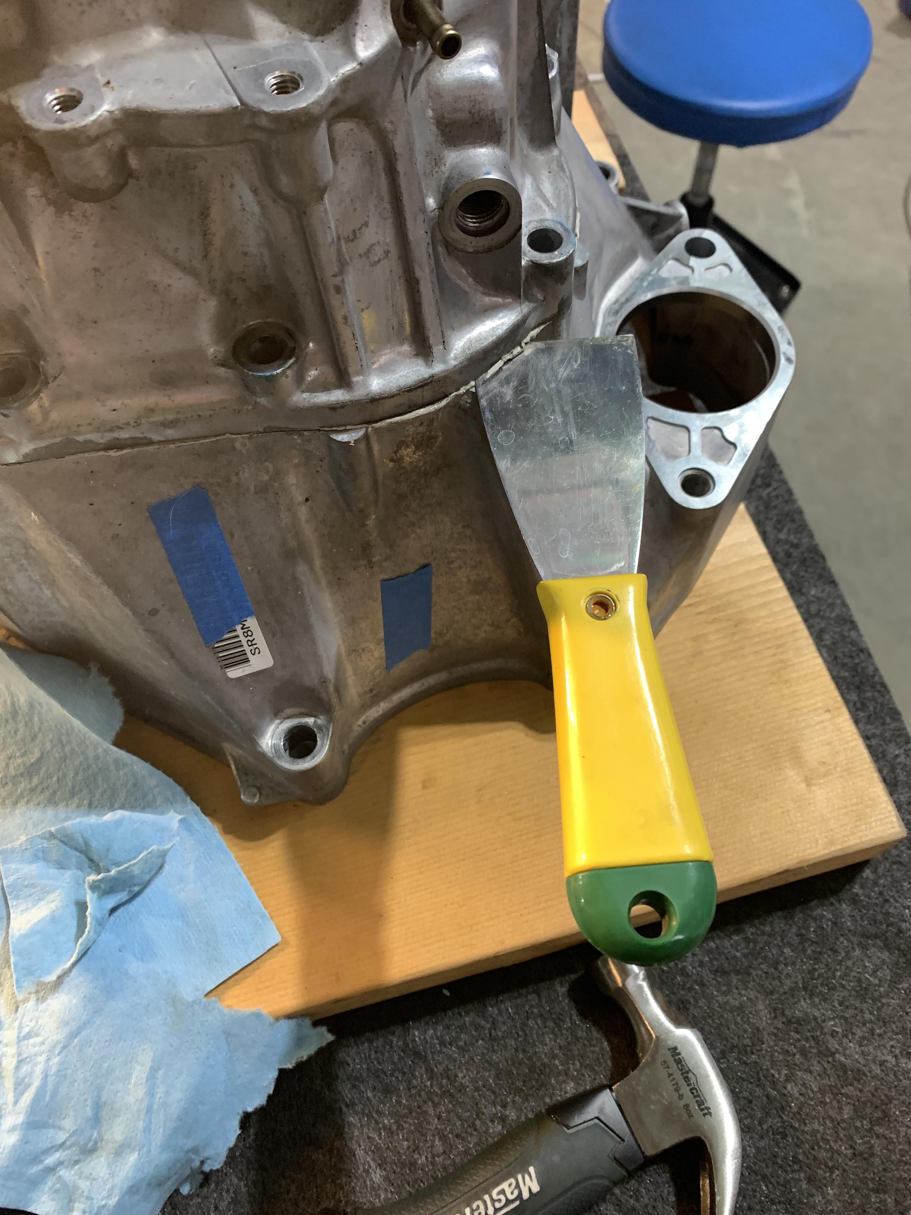
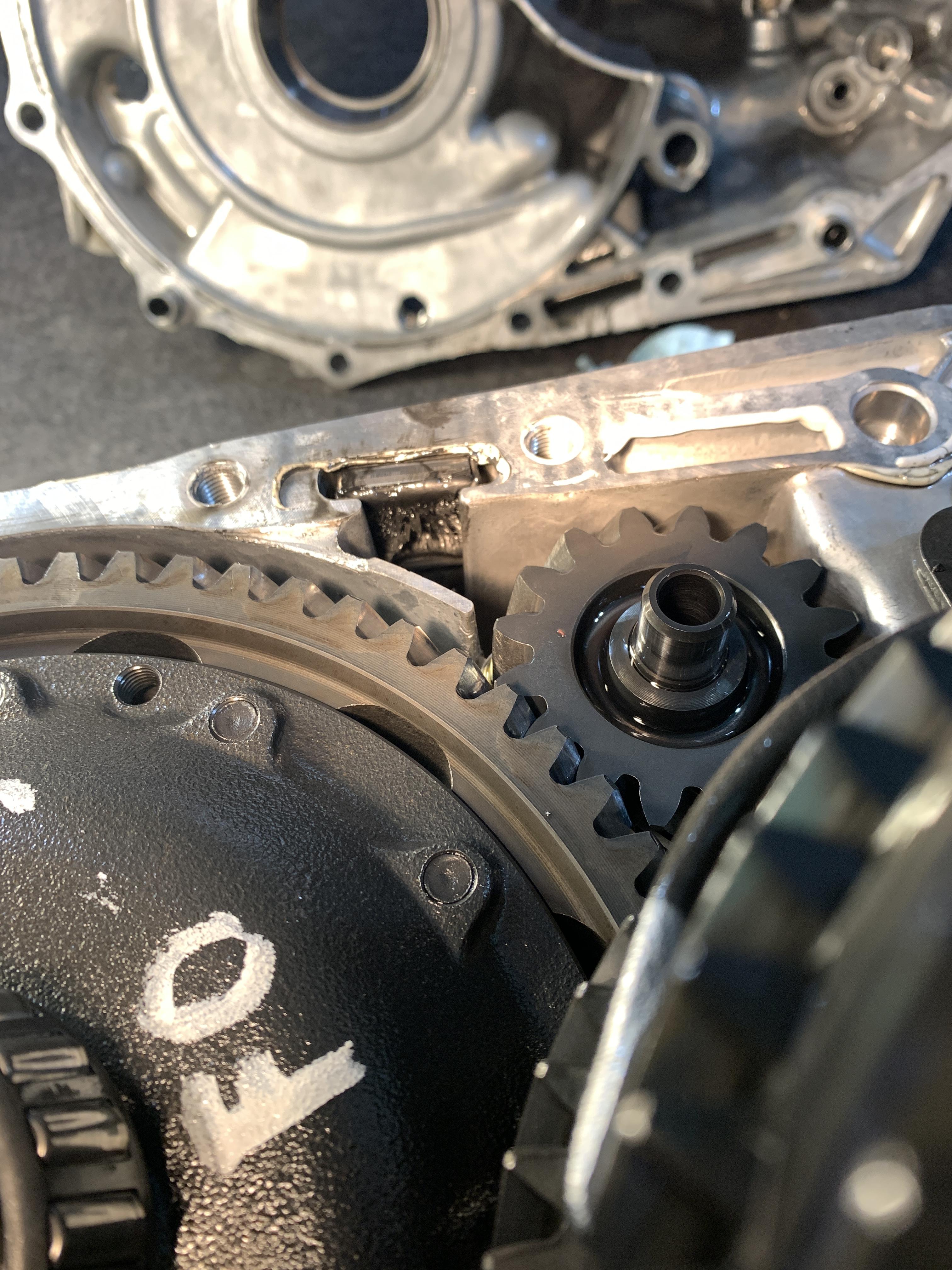
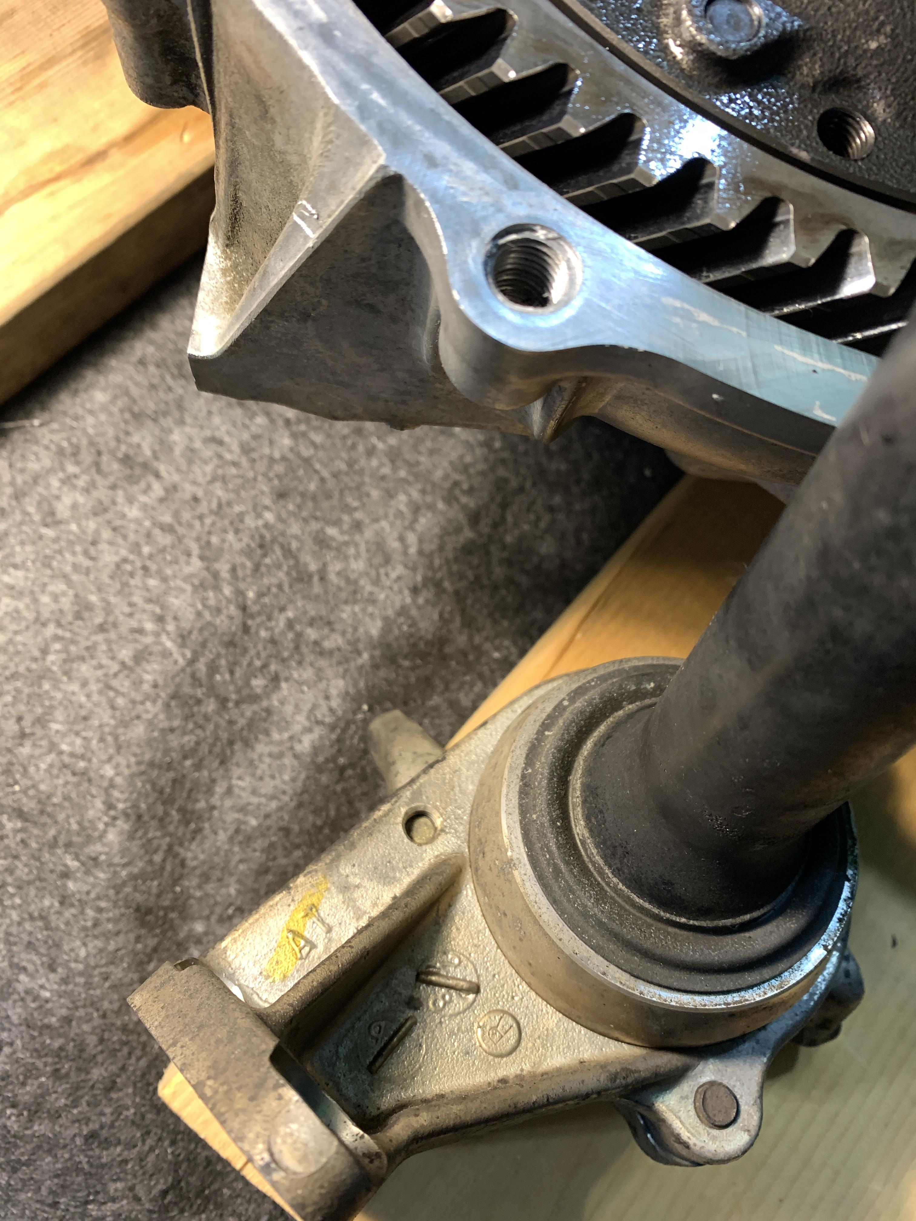
- Main crank pulley shield
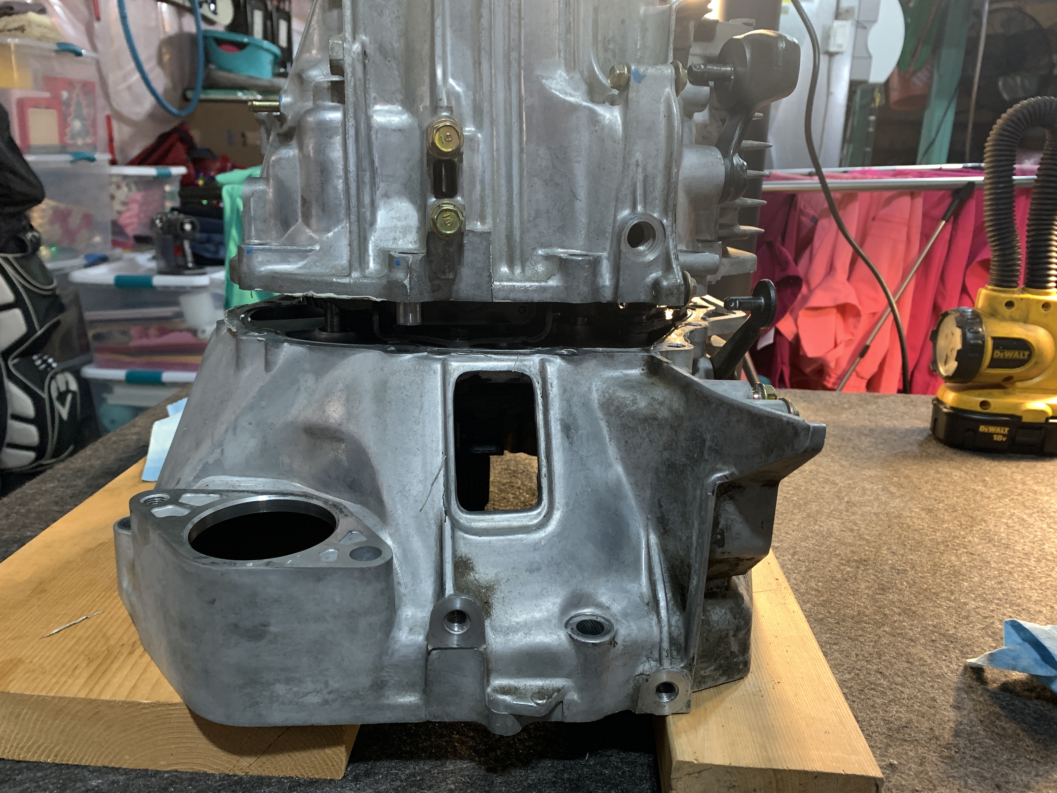
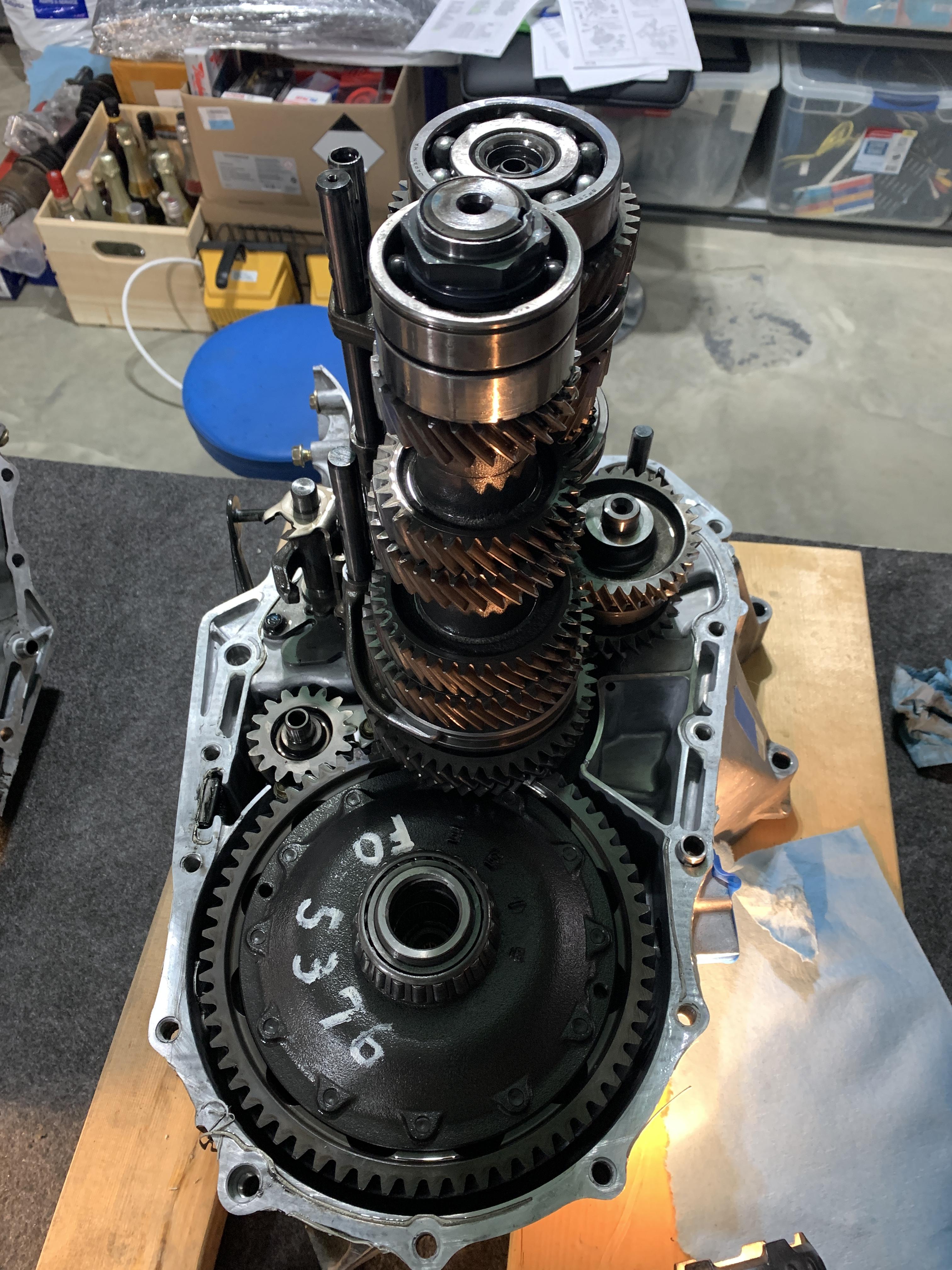
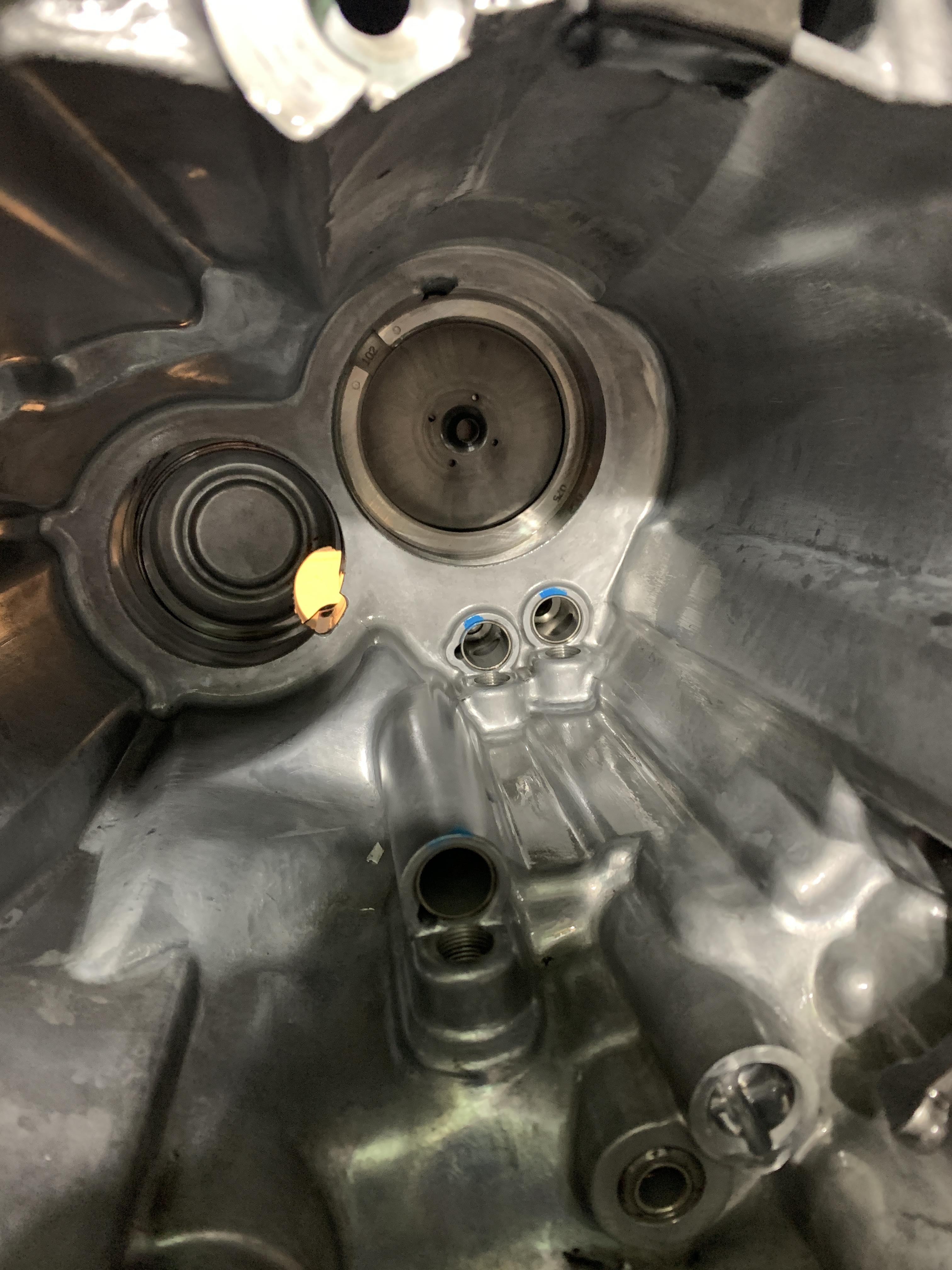
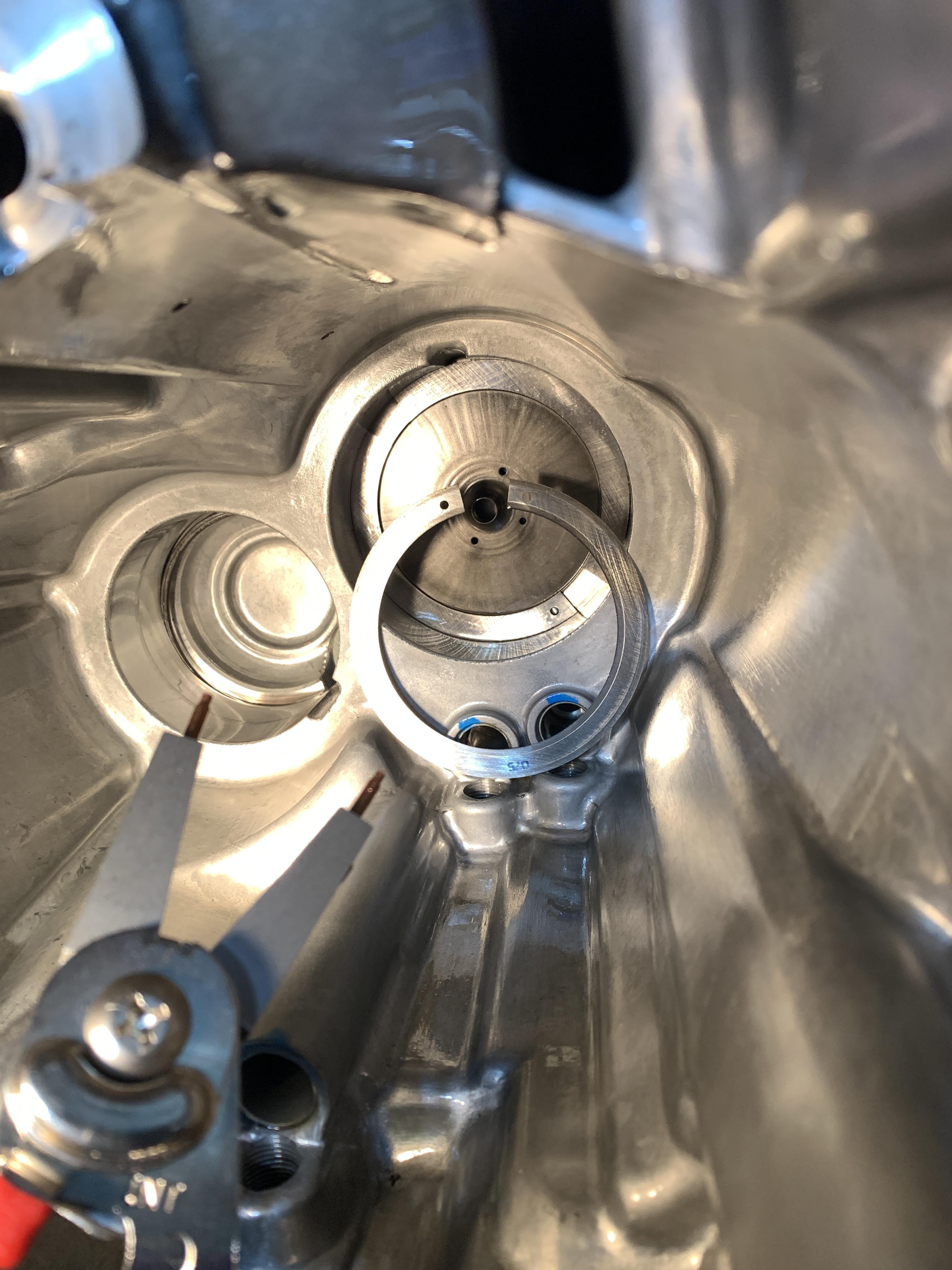
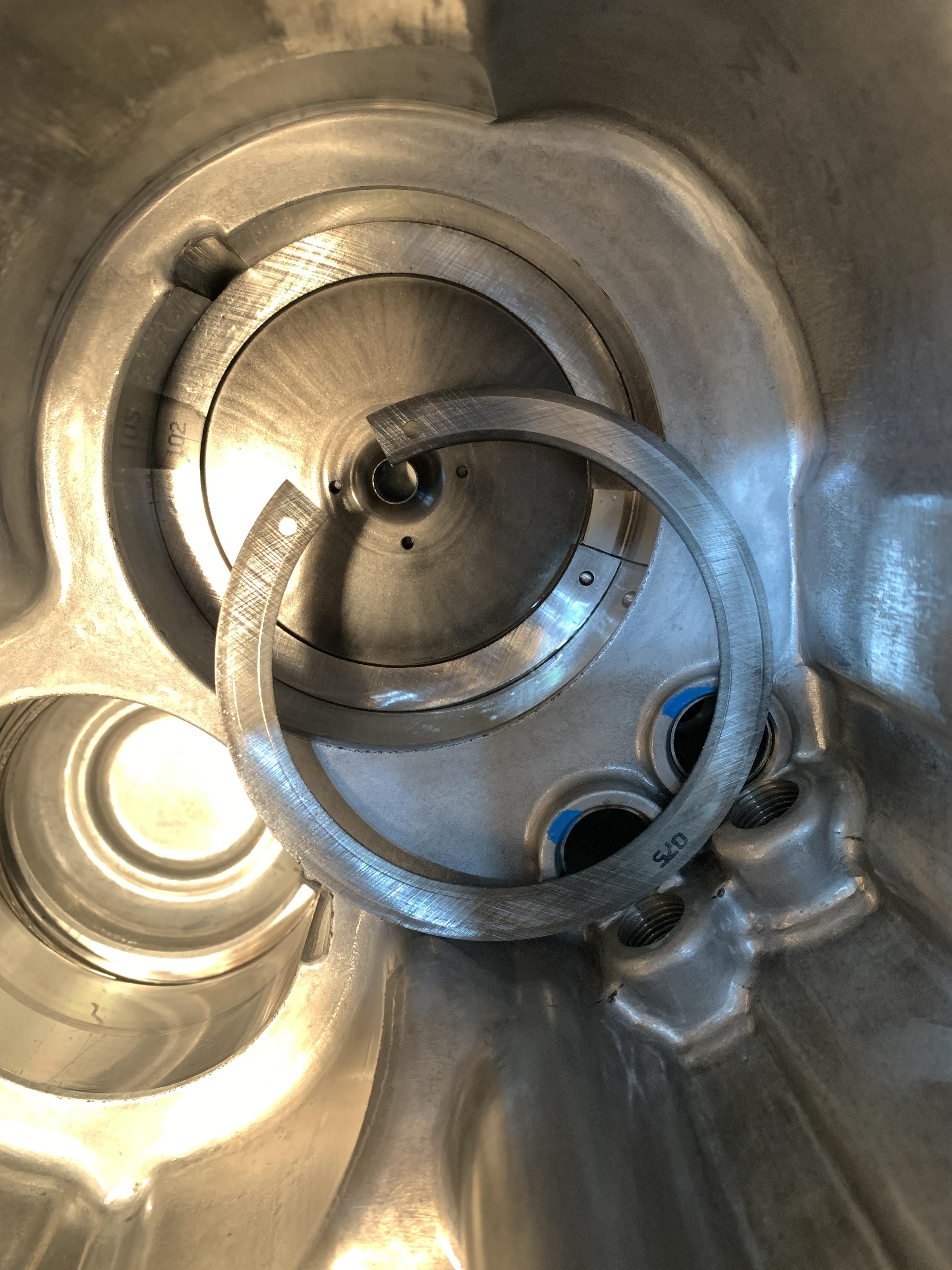
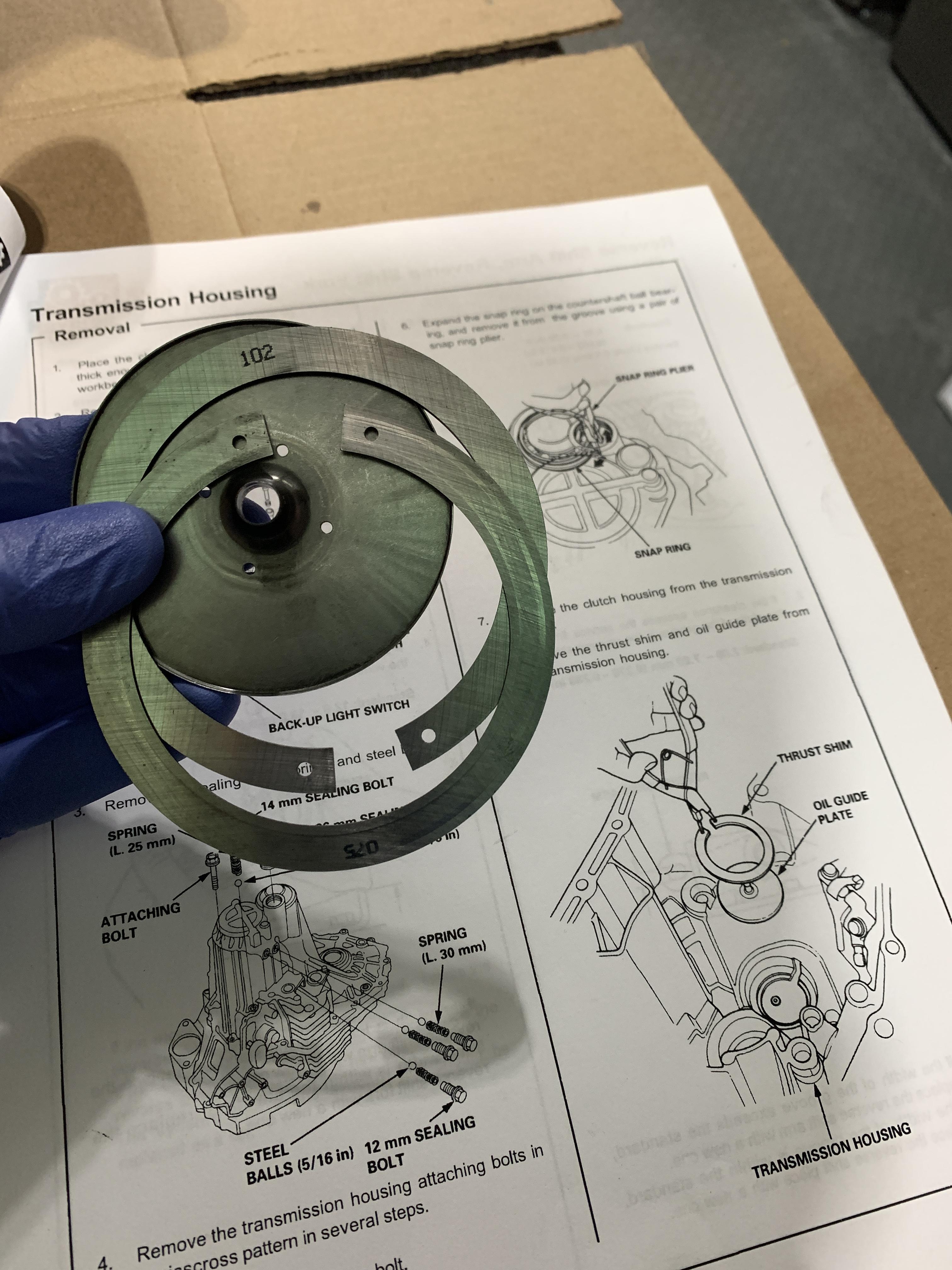
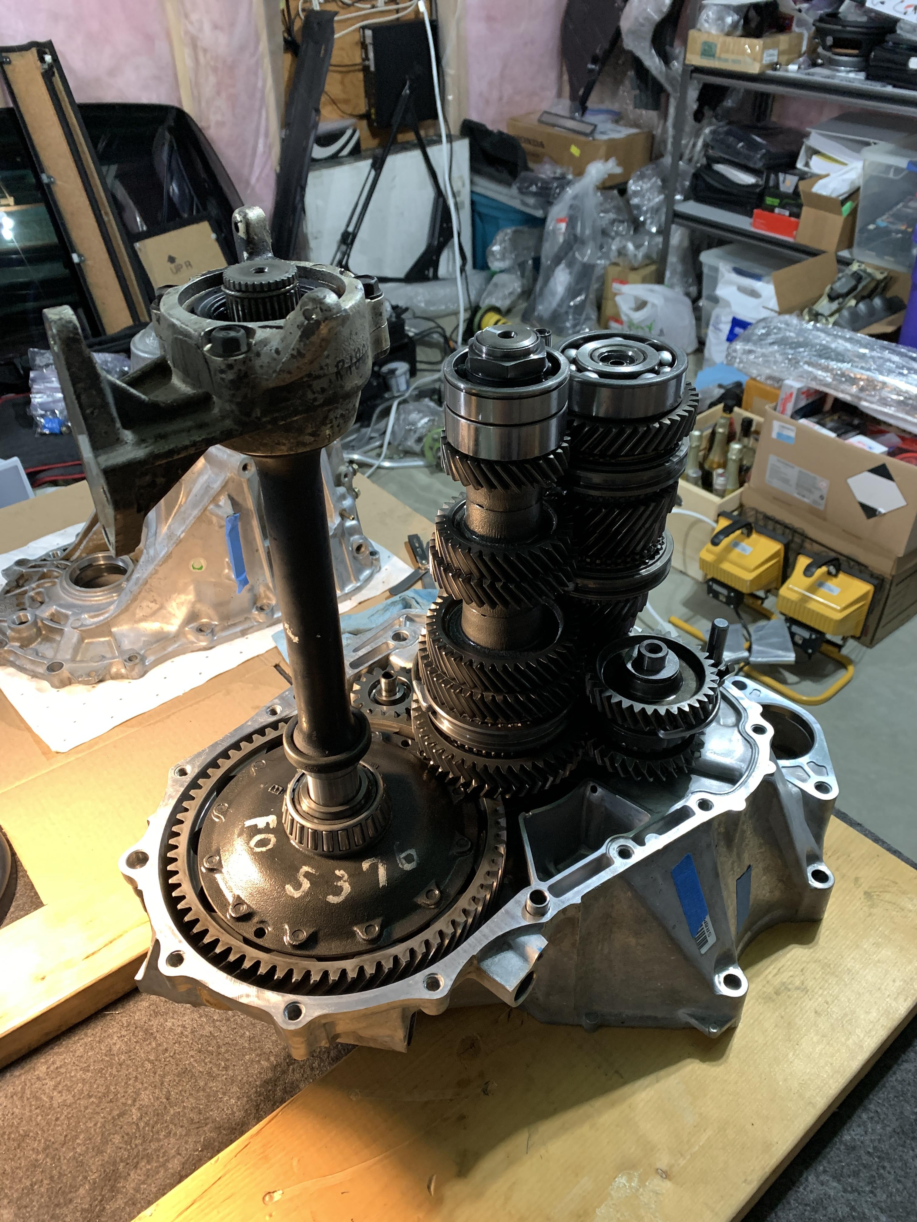
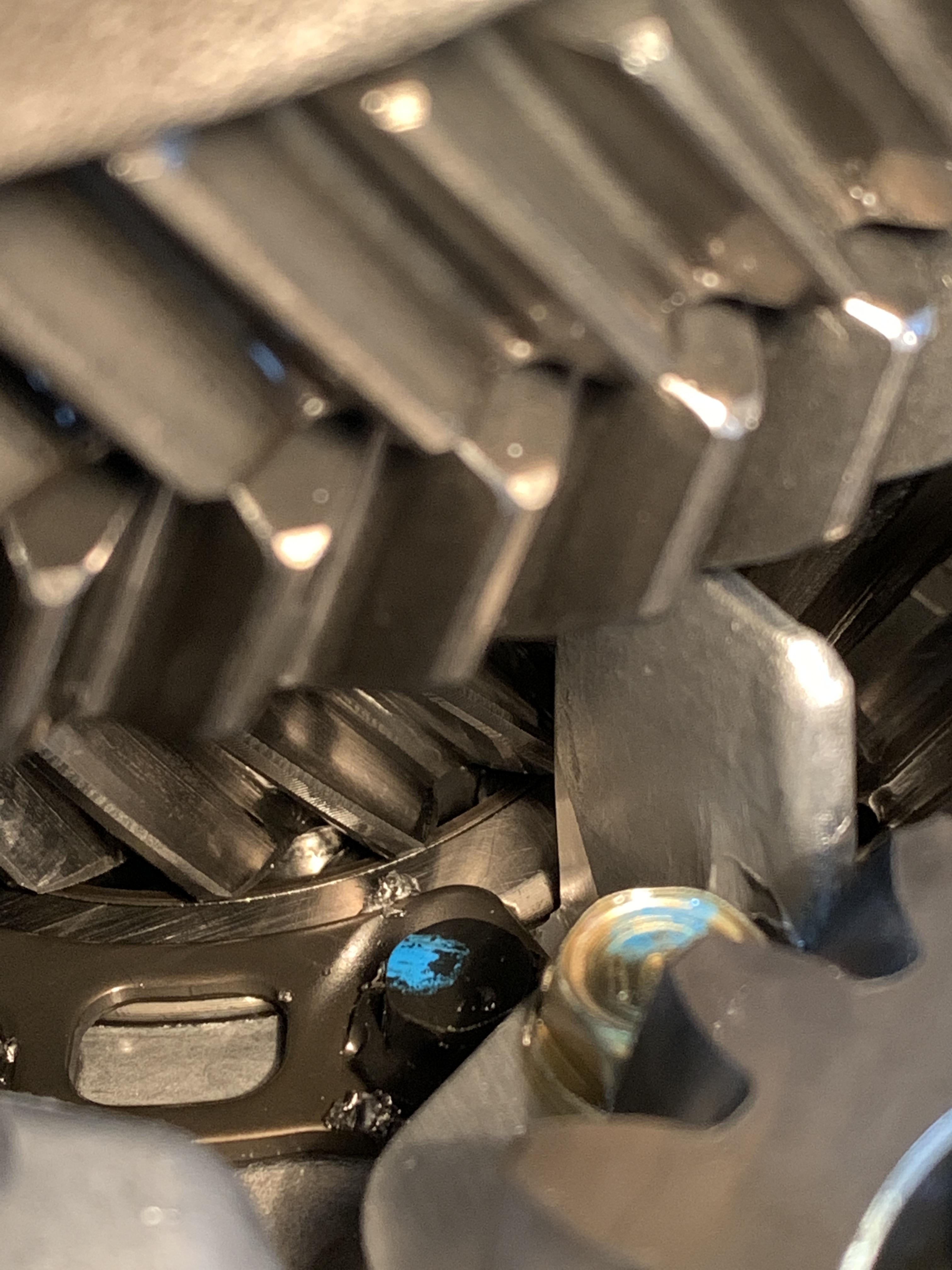
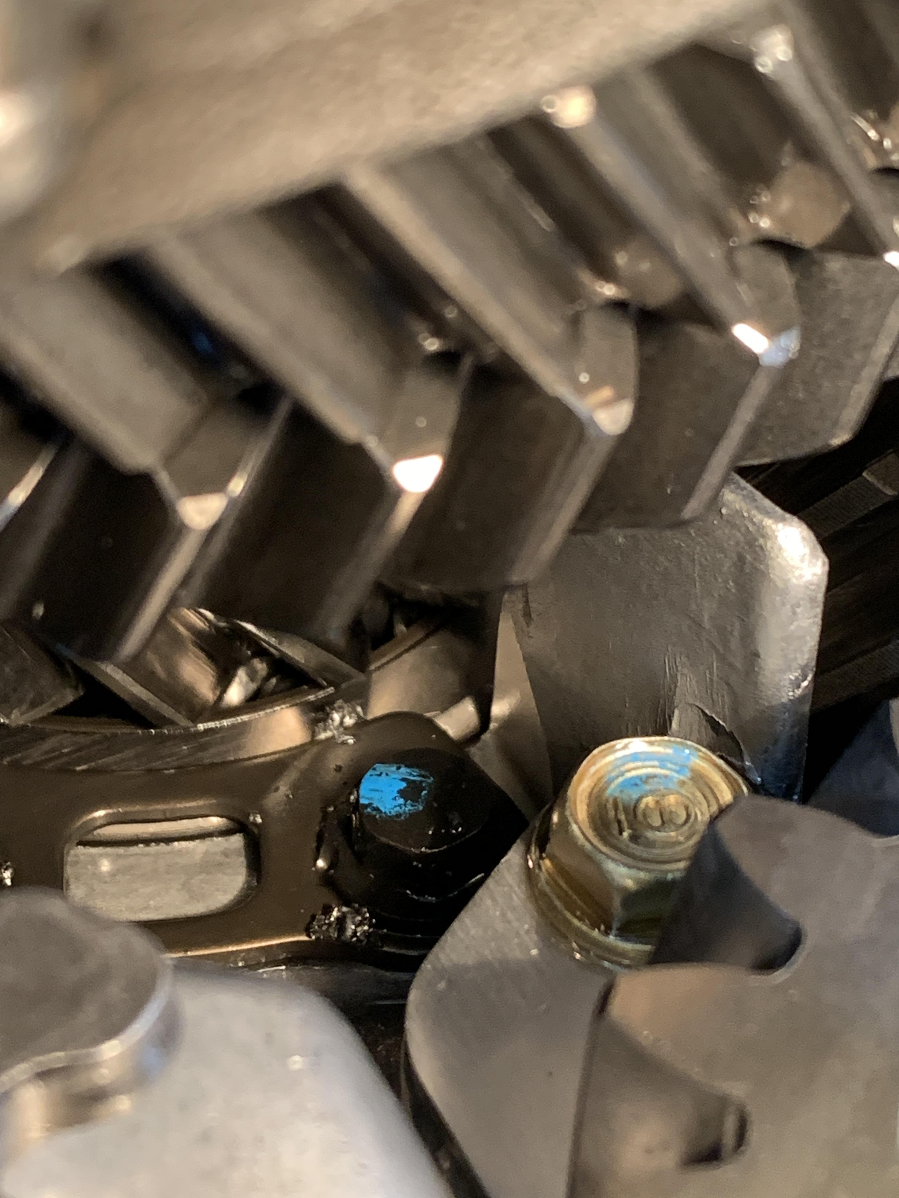
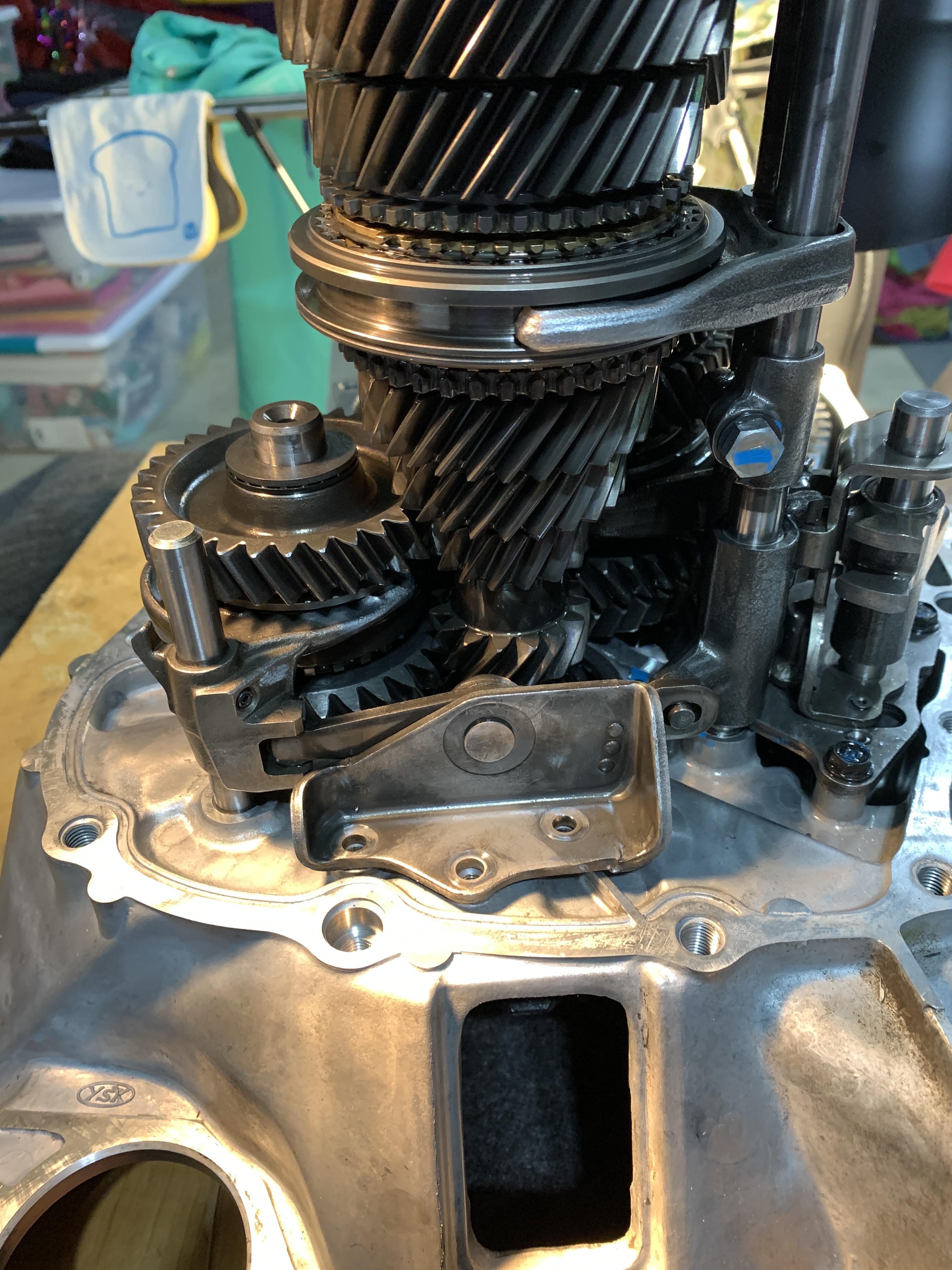
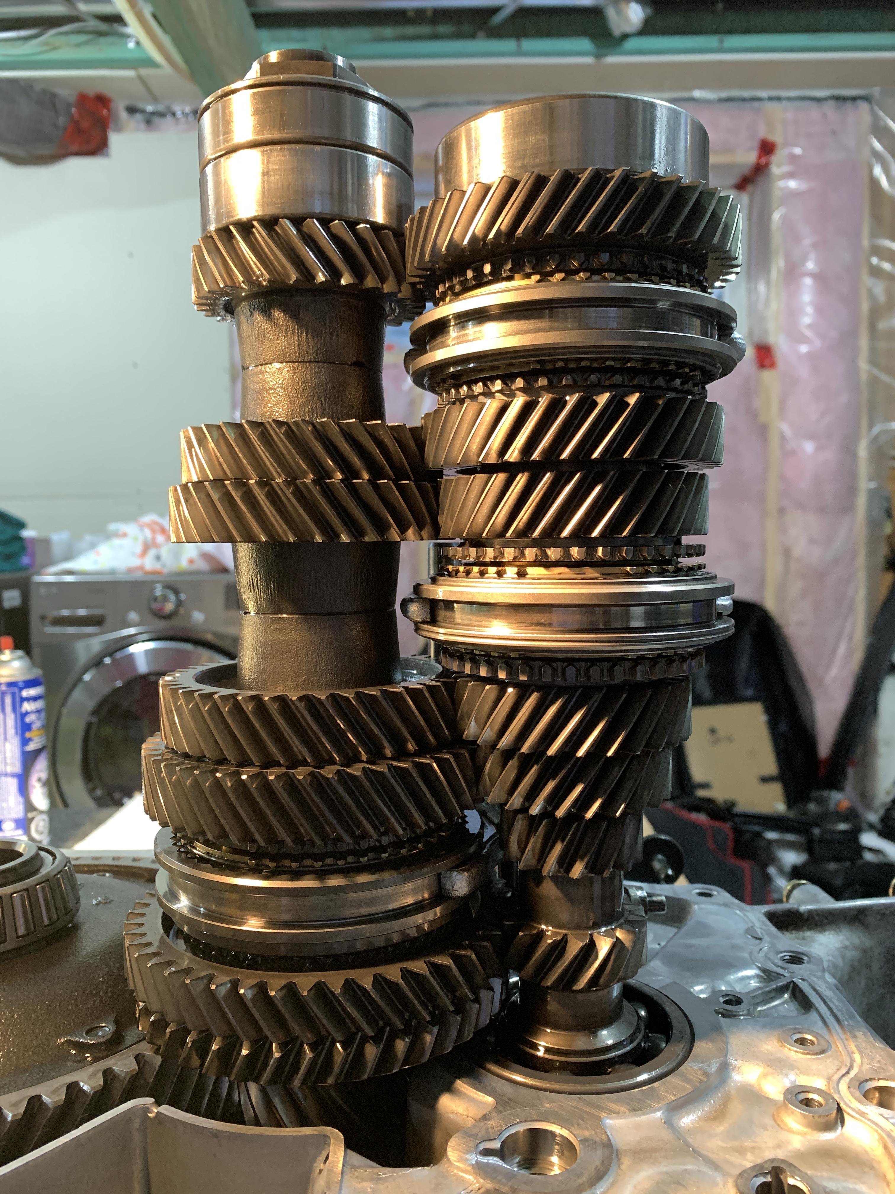
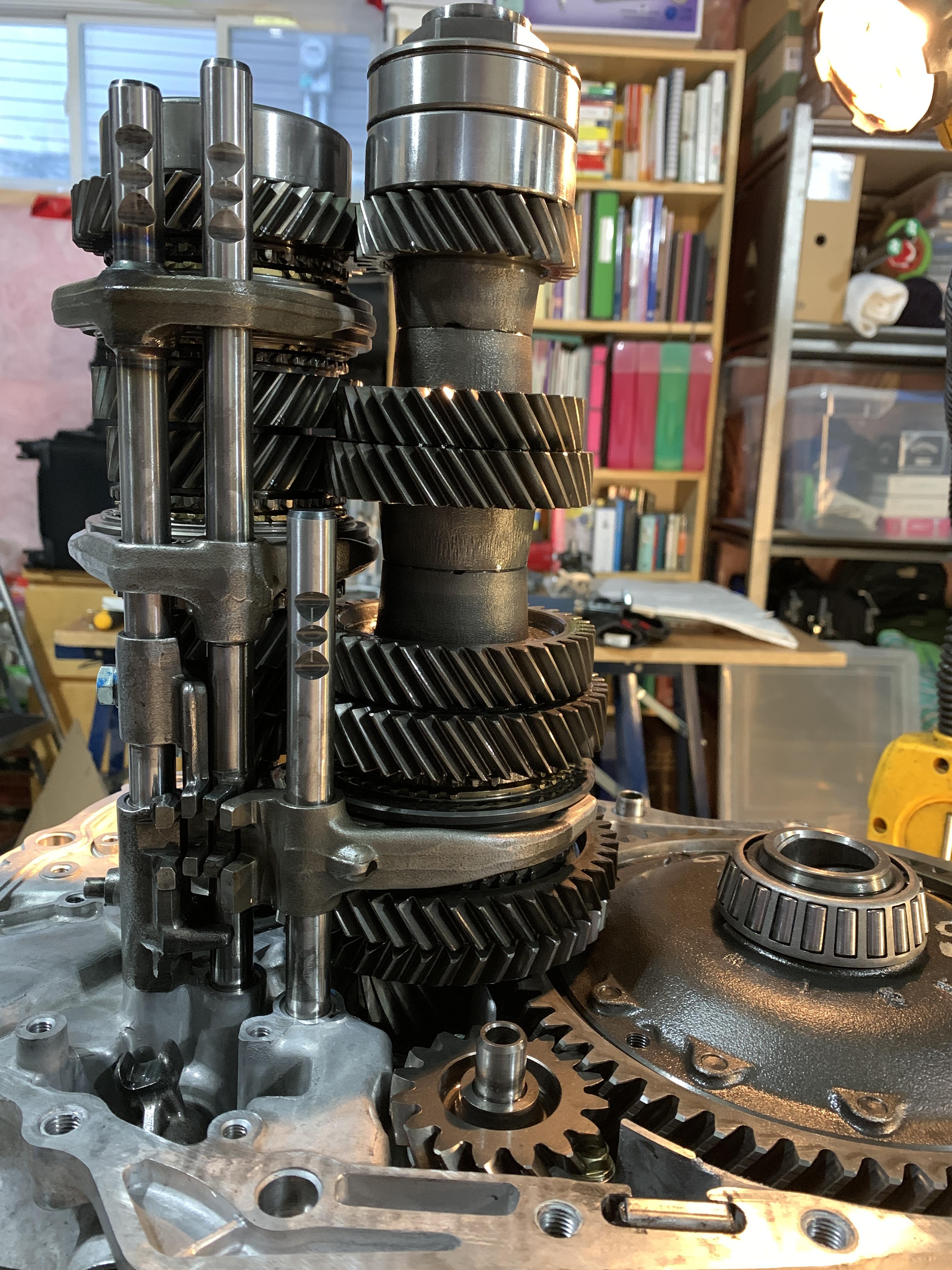
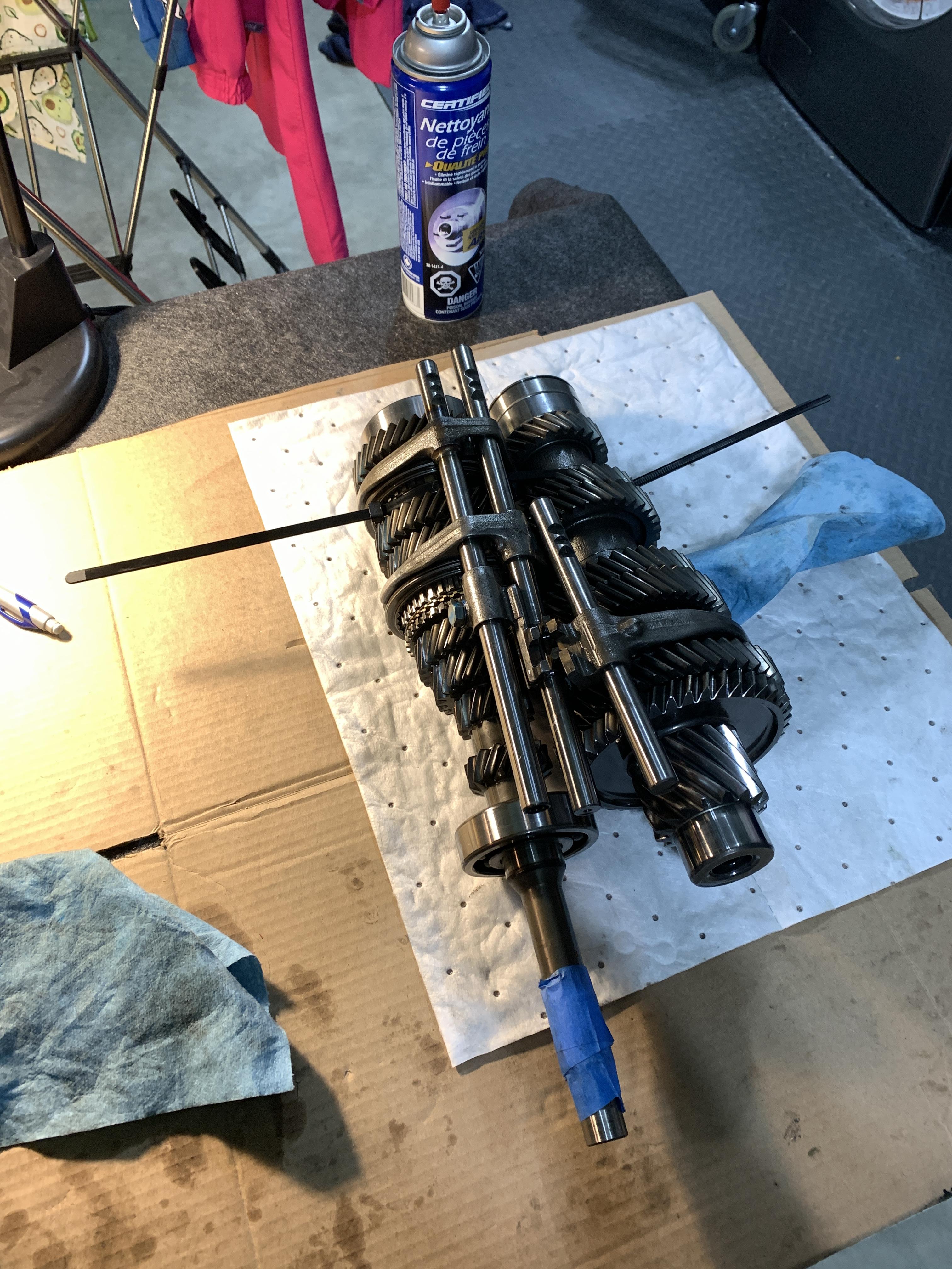
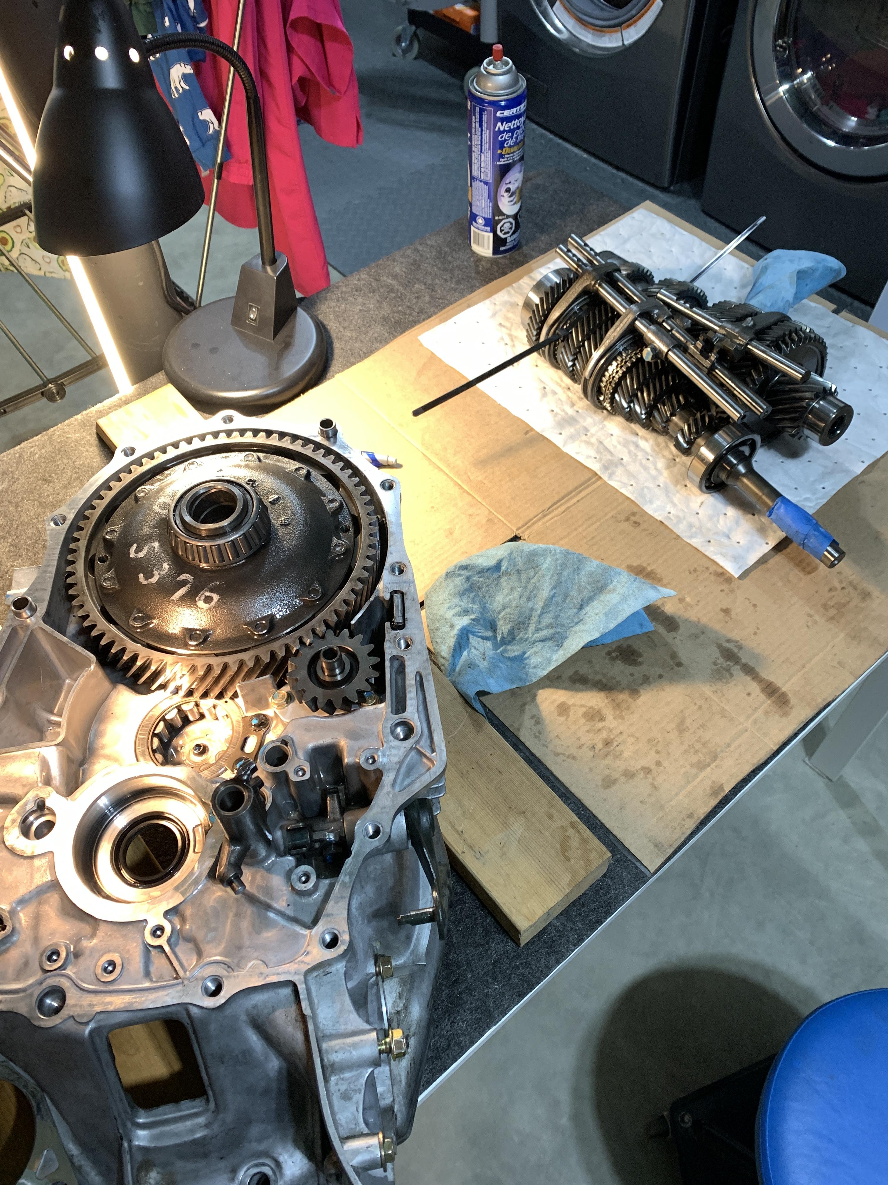
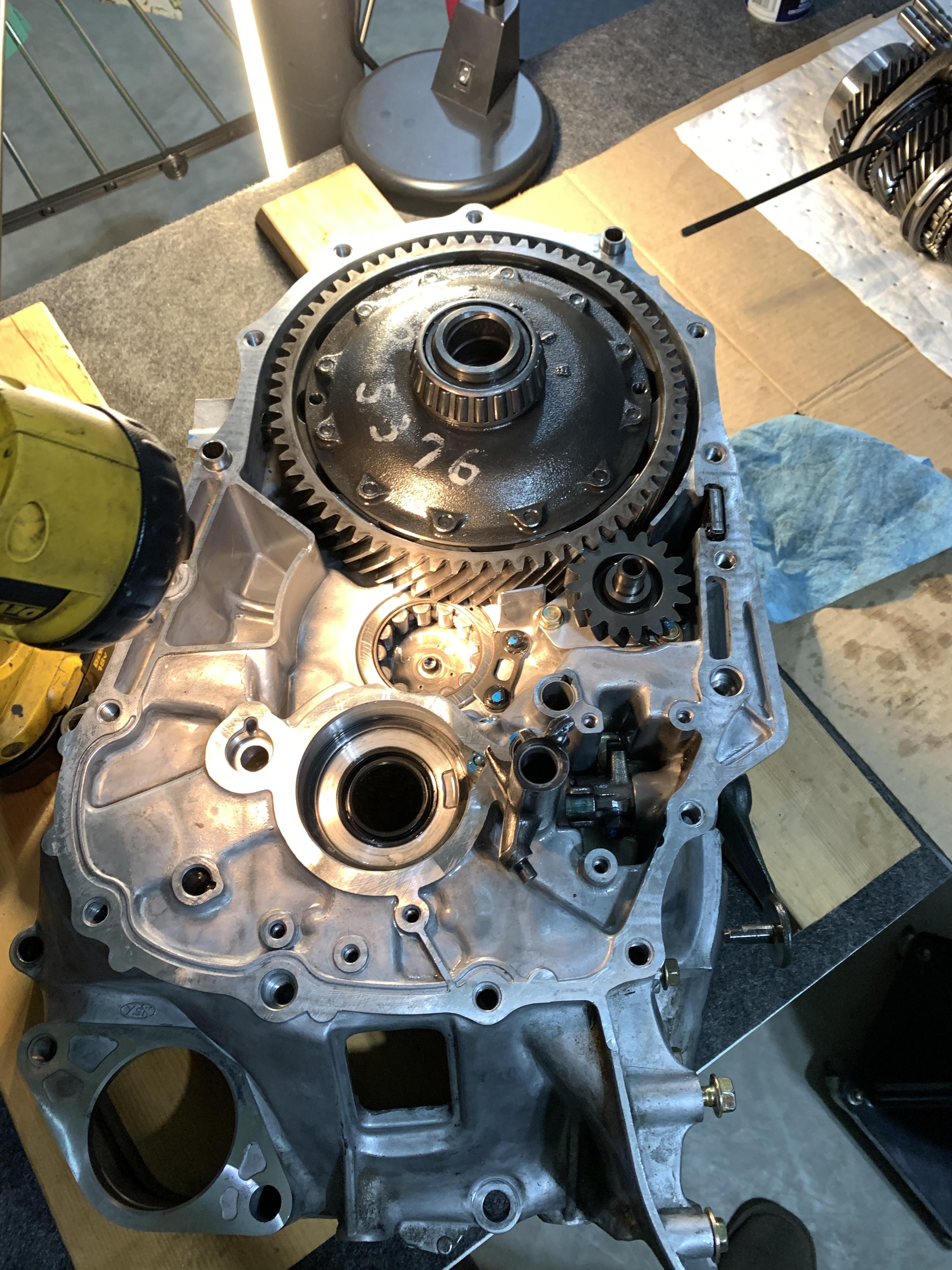
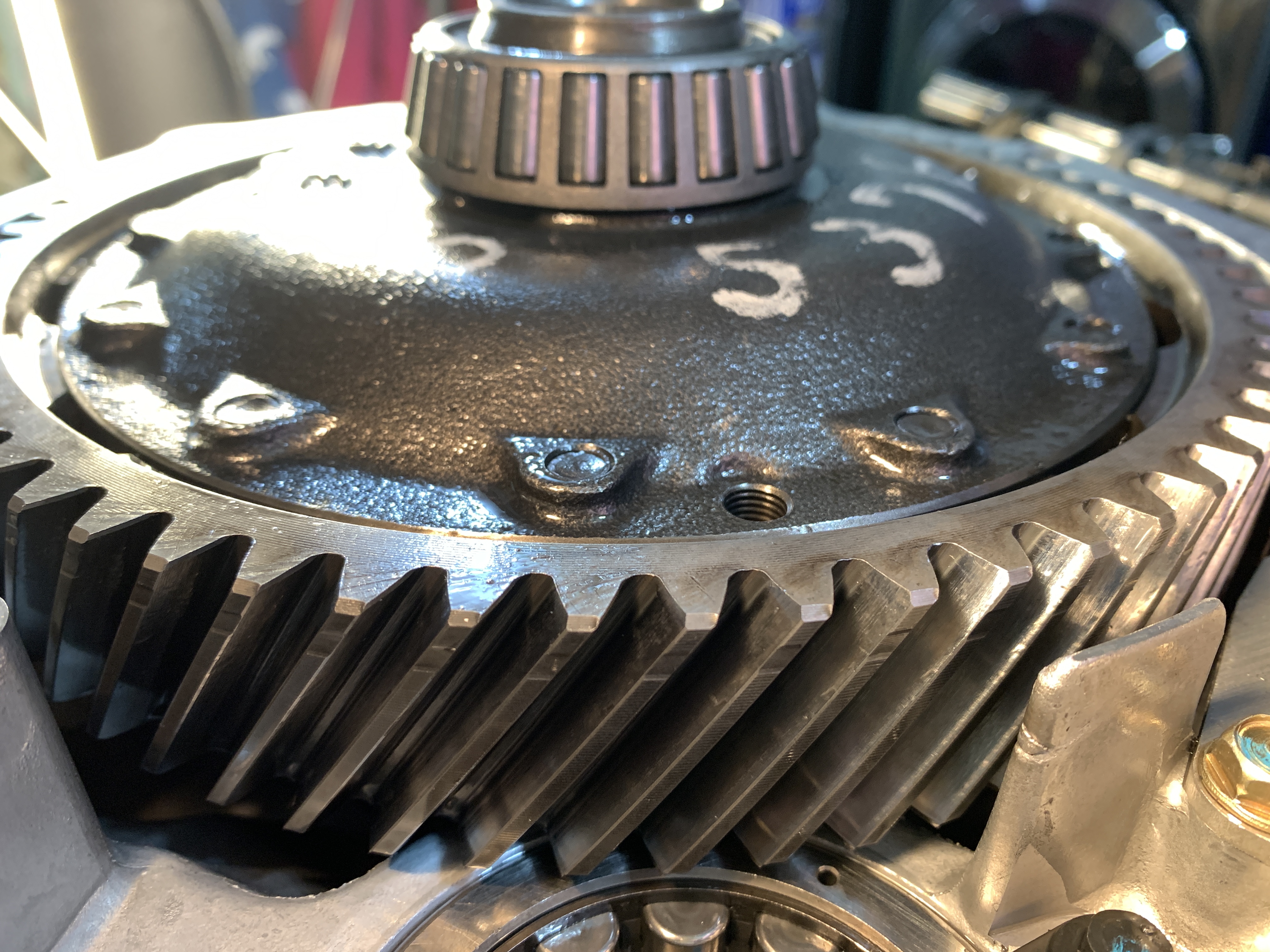
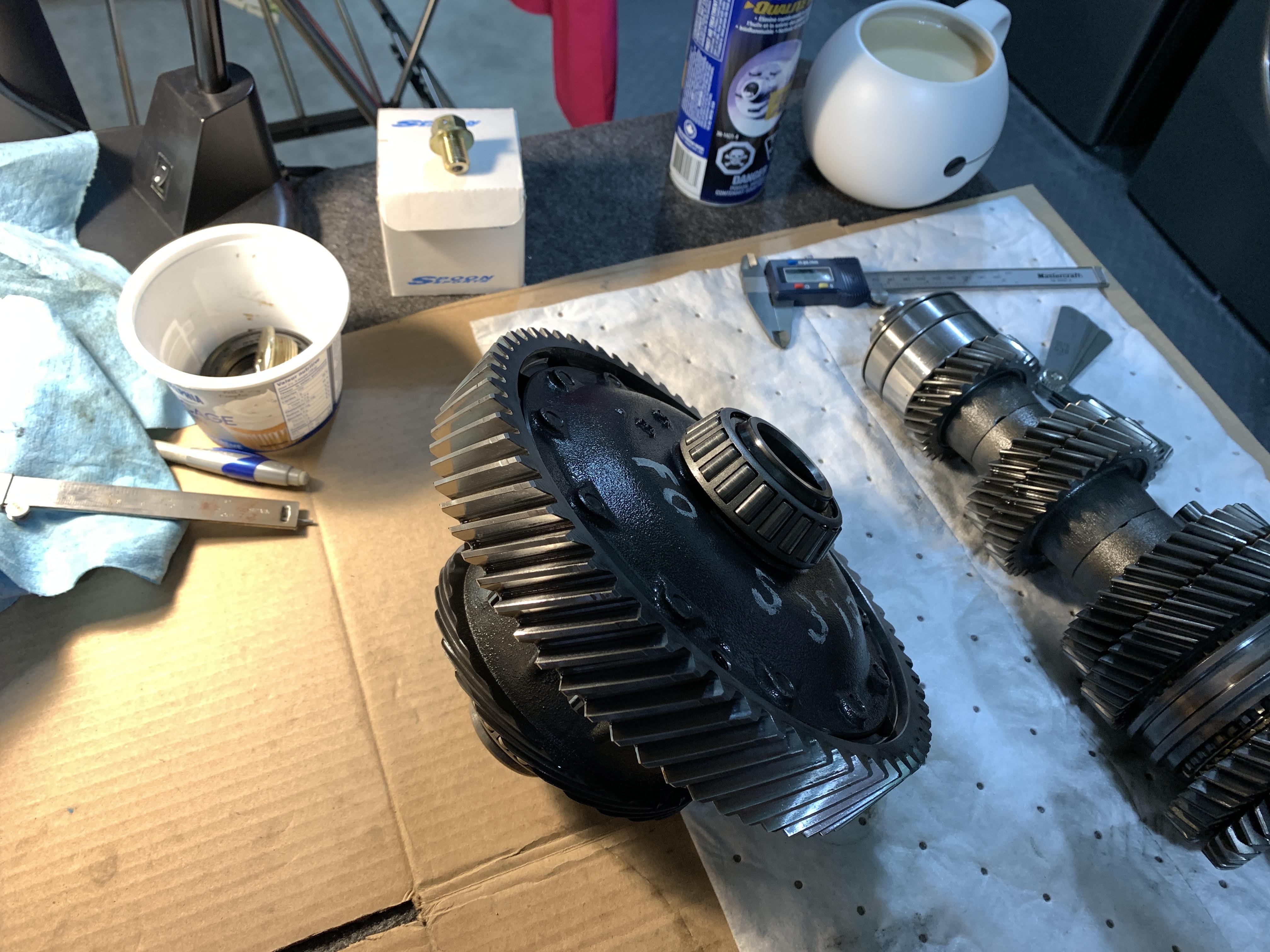
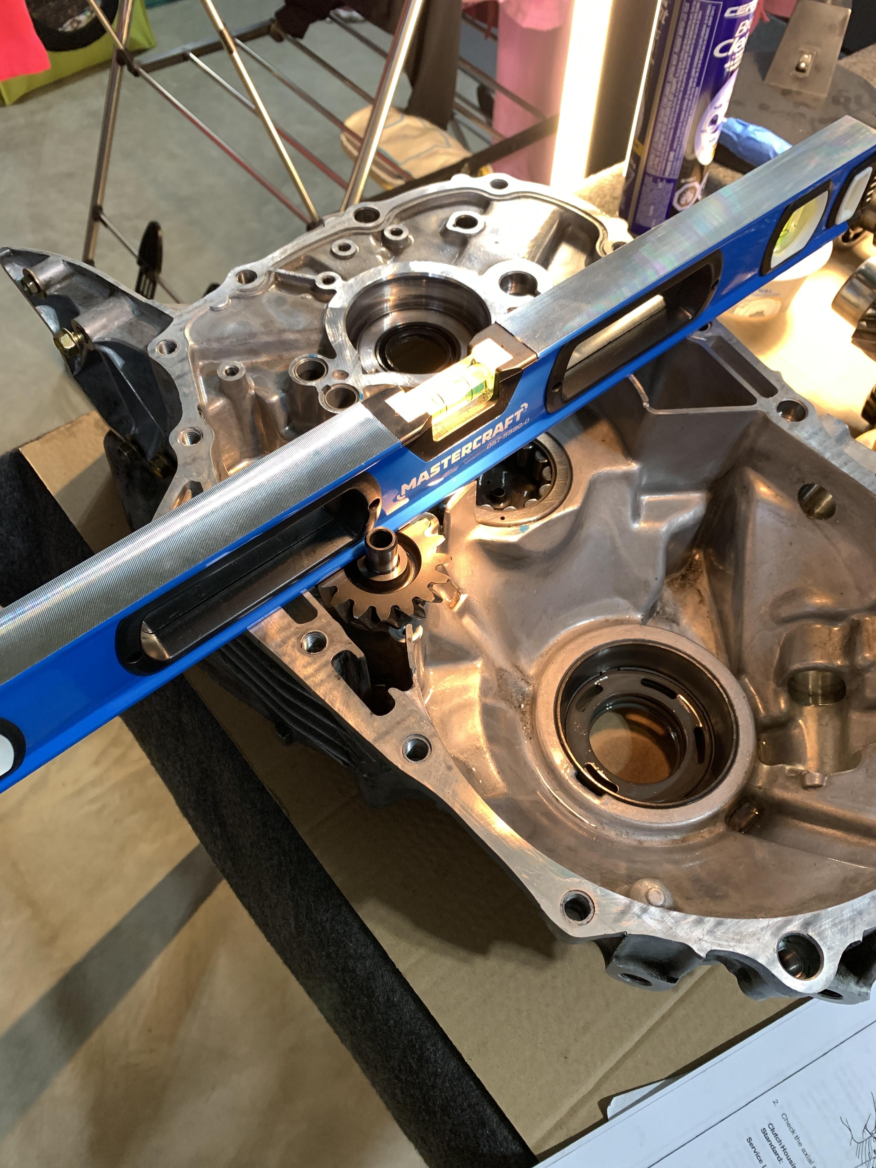
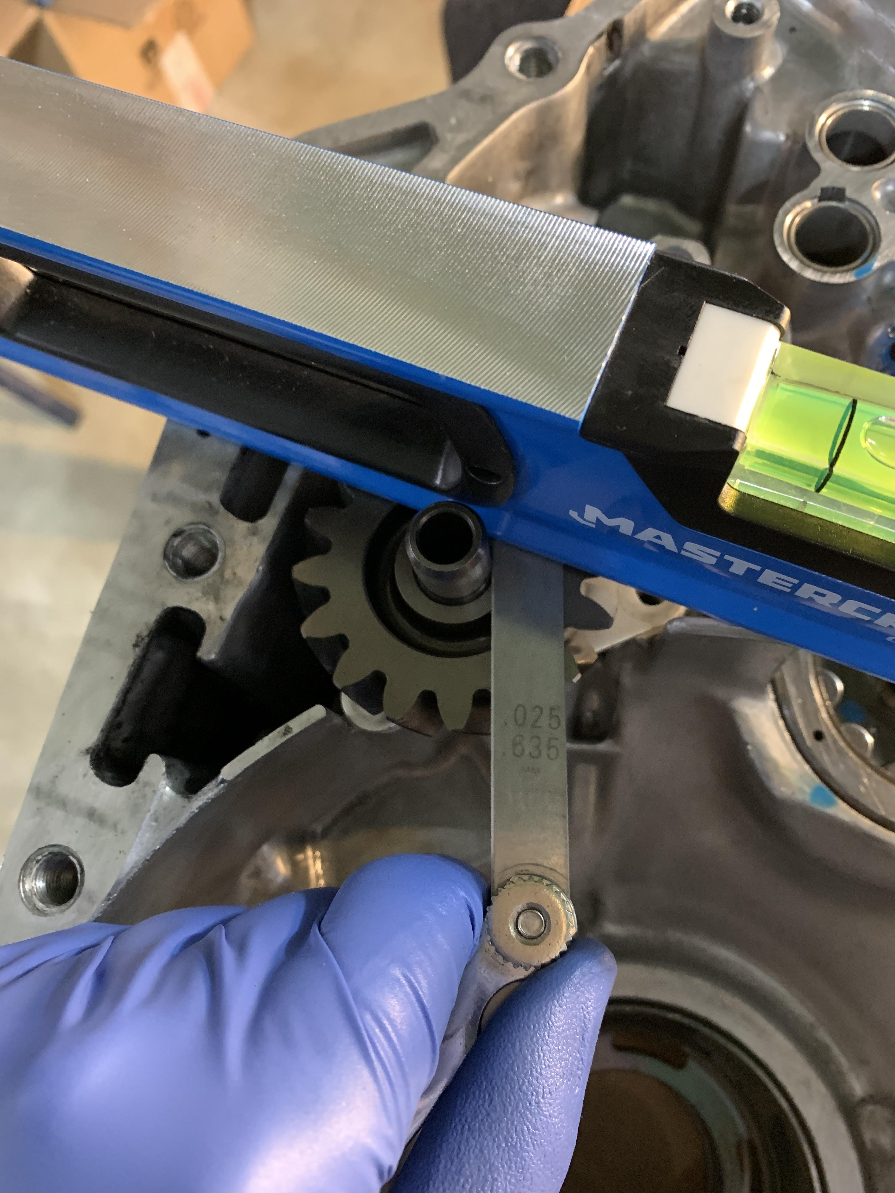
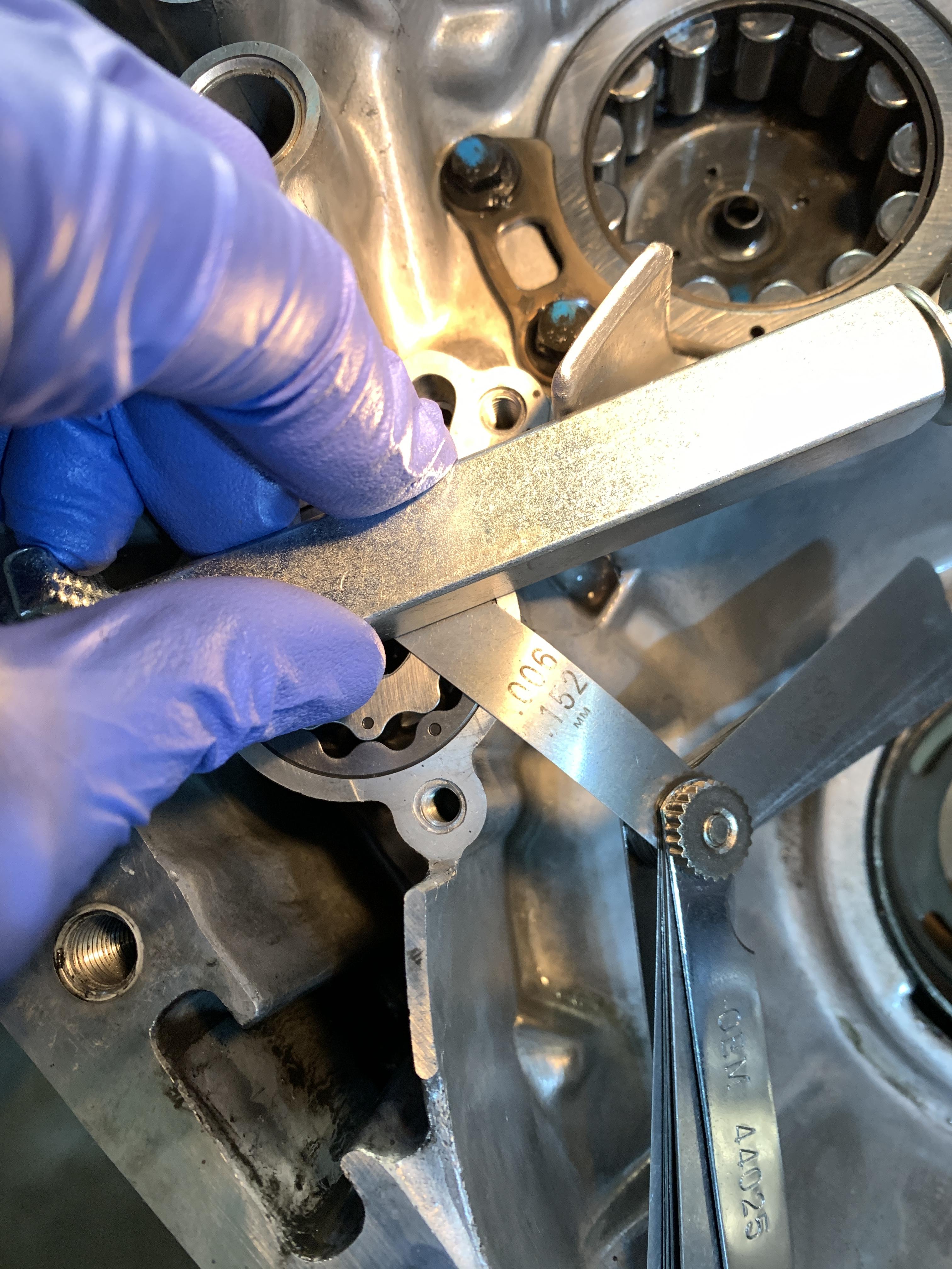
- All the tranny rebuild stuff like bearings as mentioned
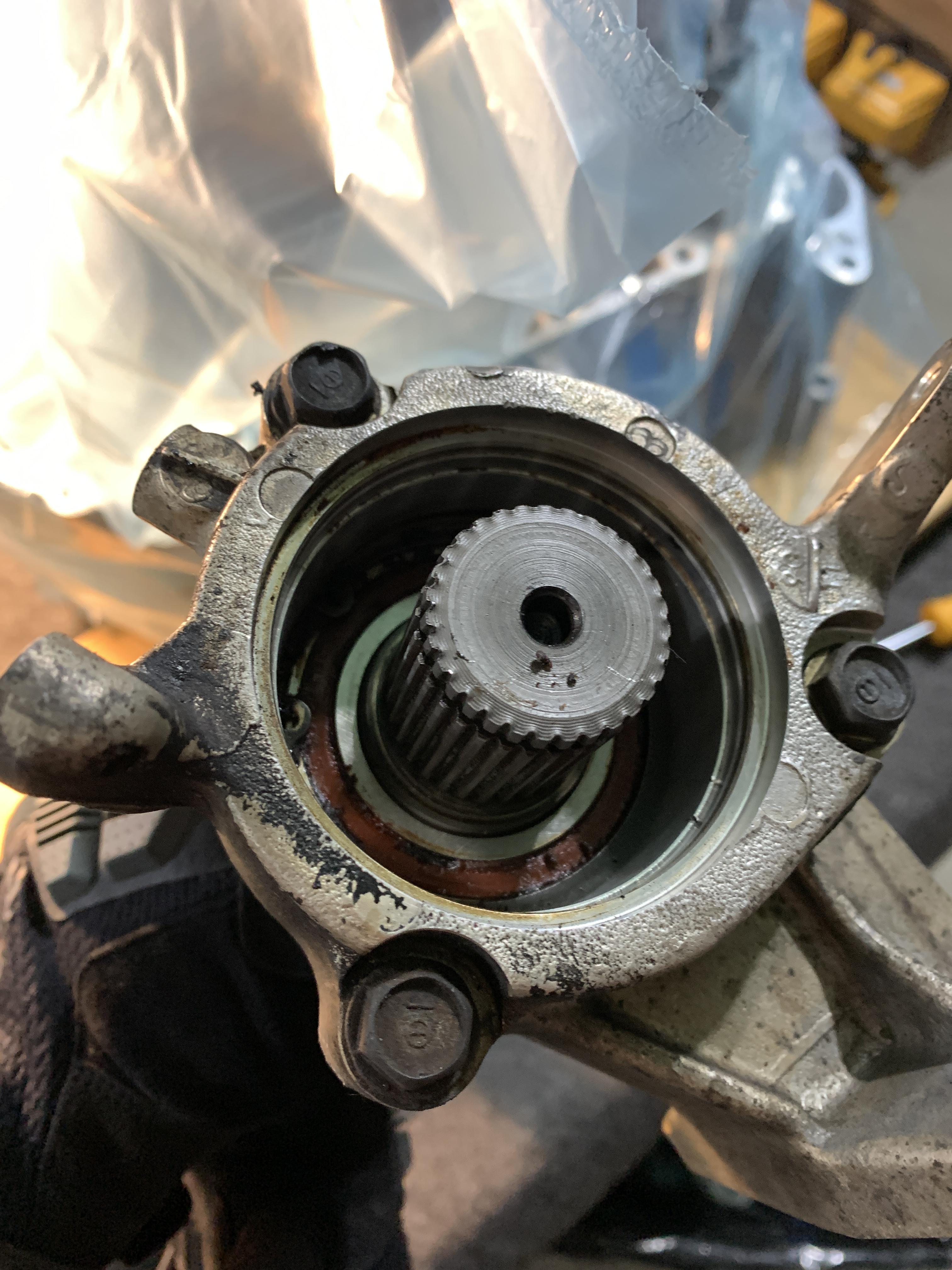
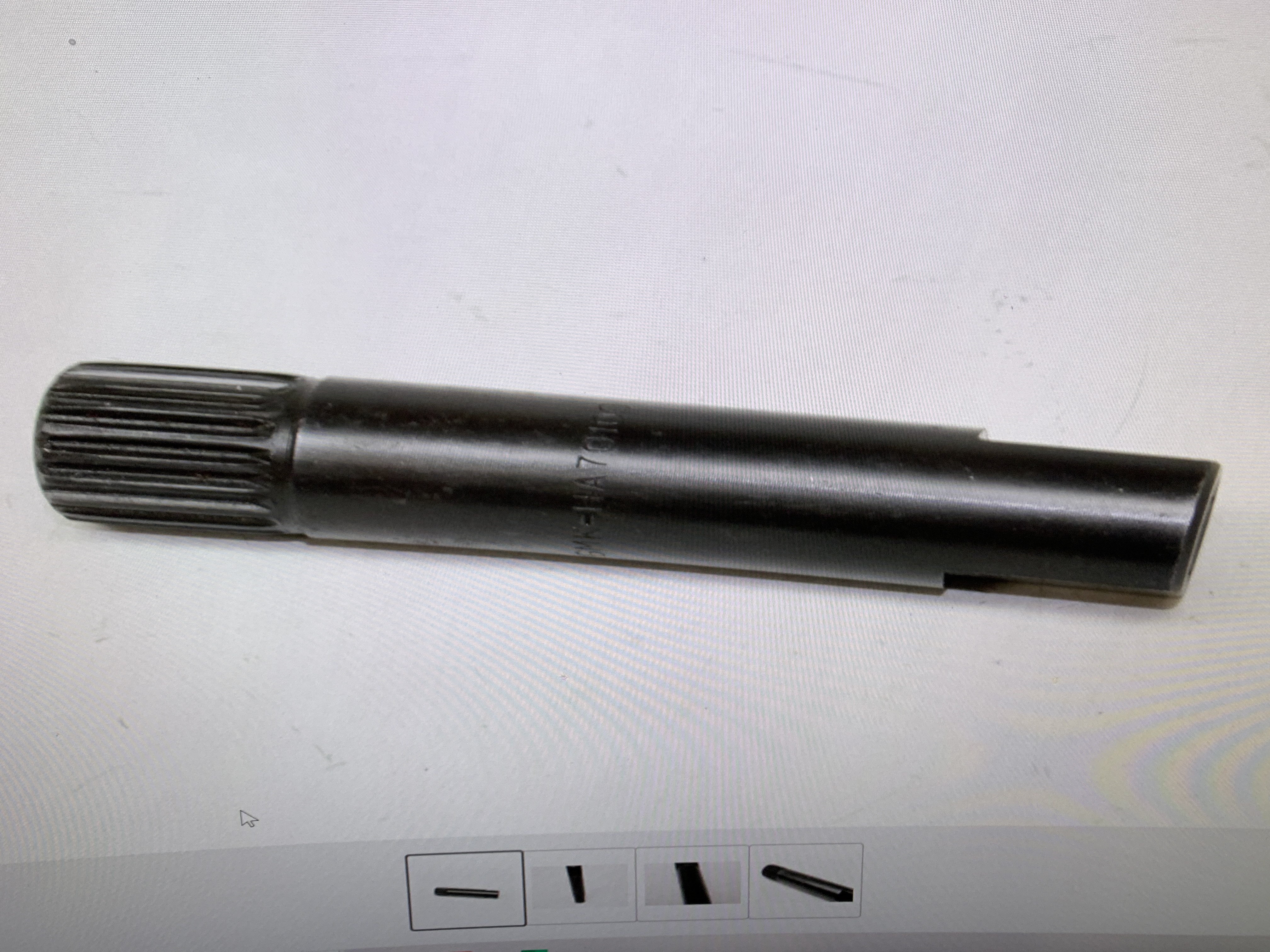
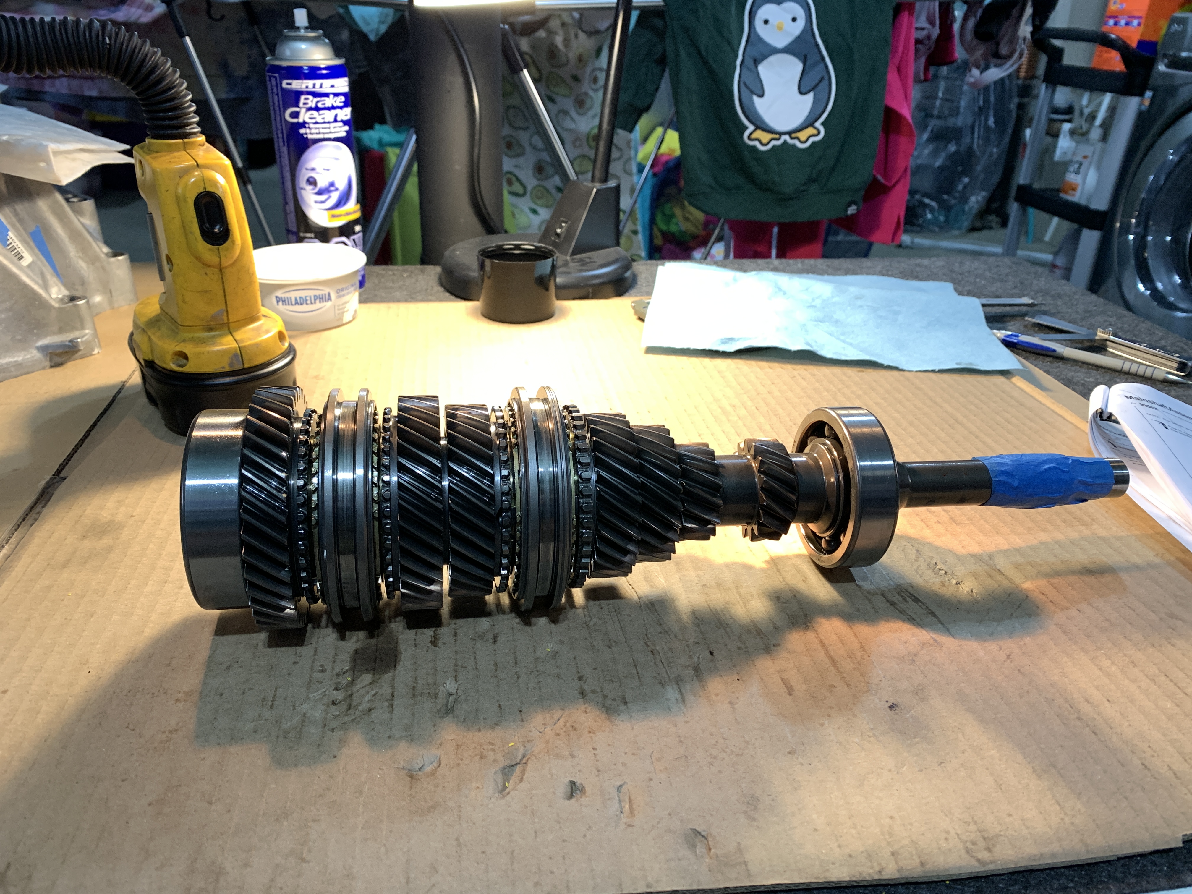
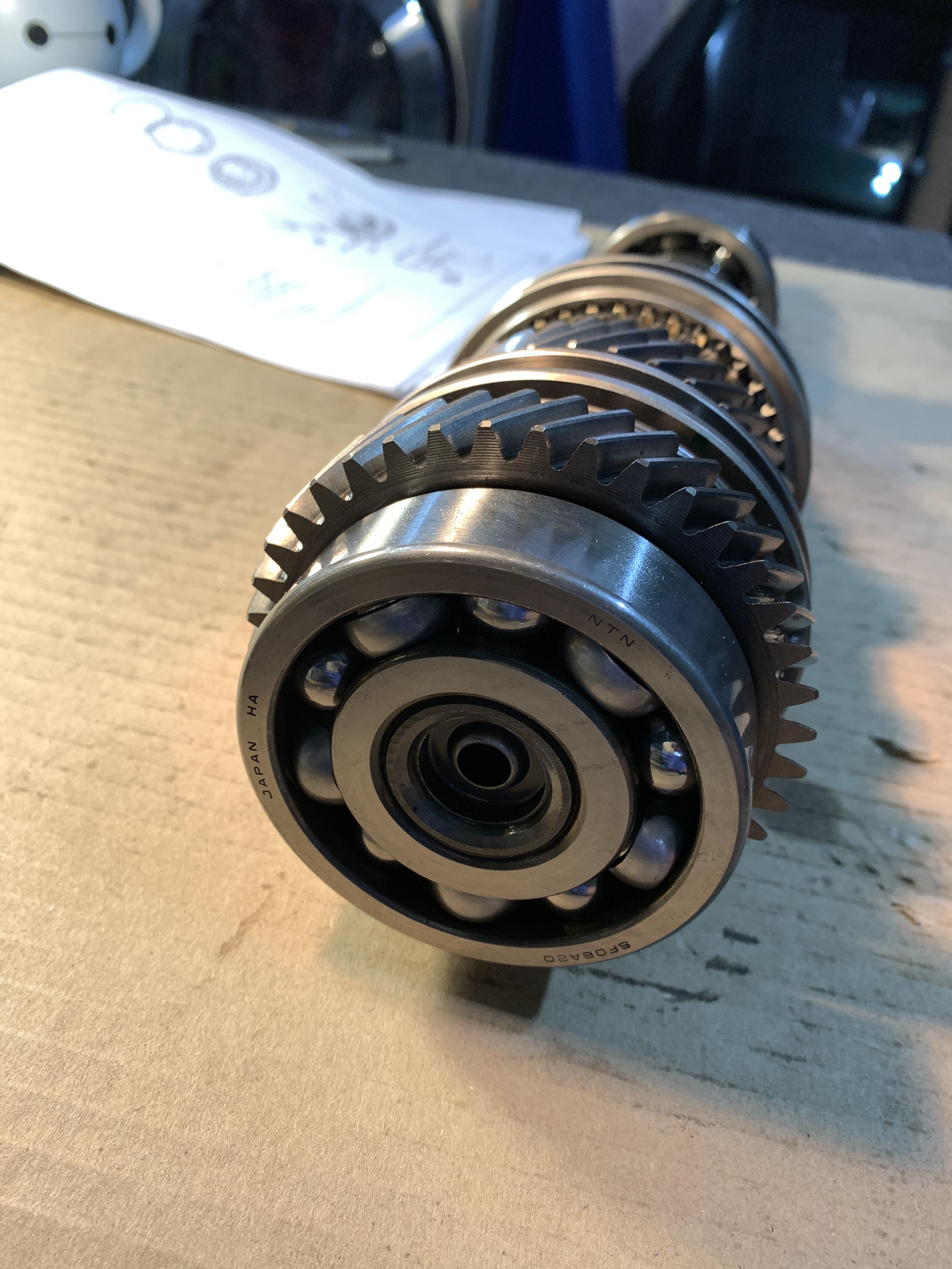
- If this car is a keeper I'd consider swapping the input shaft to a dual spline NSX-R shaft that allows you to use a twin disc clutch which are more readily available in various options. IIRC the dual spline input shaft is backwards compatible with the stock 6spd clutch (double check that though). 4.23 shorter final and pinion gear is also something i'd consider. Again, not sure if these are priorities for you. You have a very late model NSX so perhaps not.
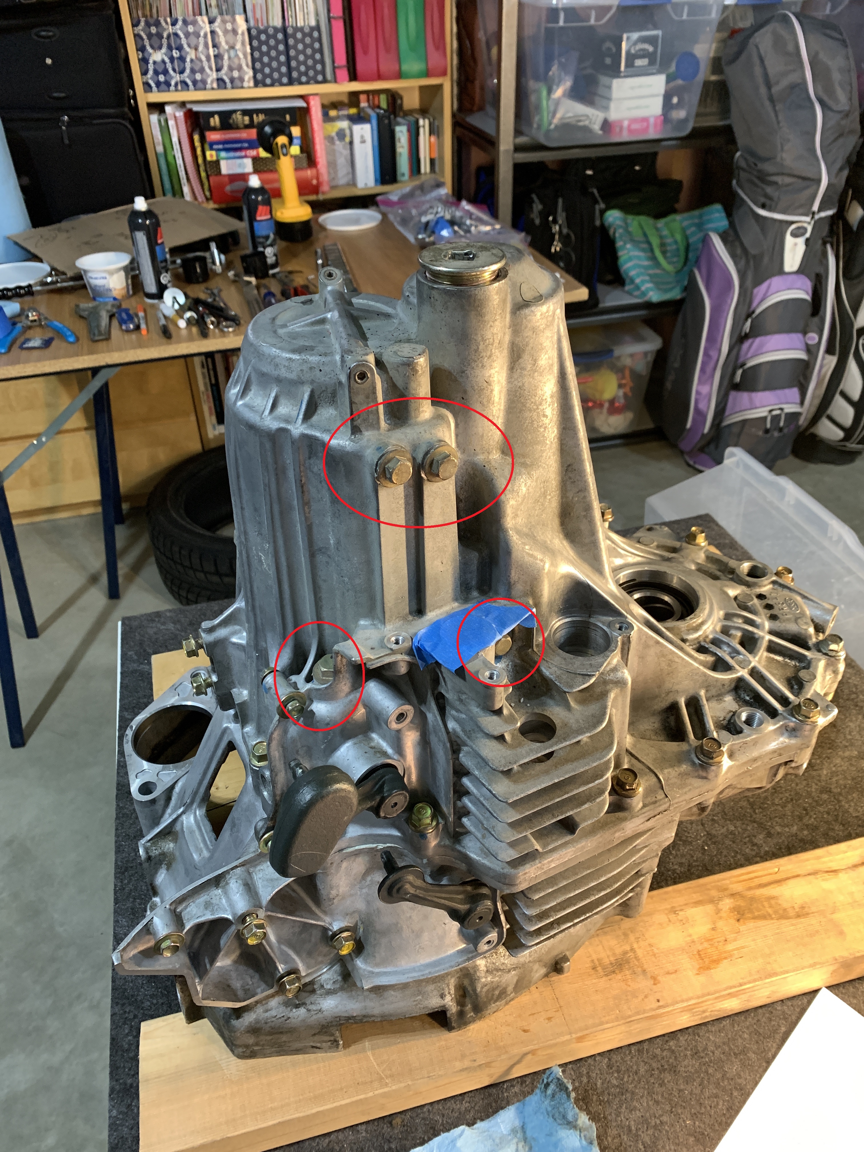
 
Thanks guys for the input. Honcho and MotorMouth I will take pictures and document all steps when I fully take it apart over the Christmas break.

BMcH, my tires are absolute hot garbage! I bought them in 2010, installed them in 2011 and they're the same ones ever since. They're due for replacement but the sound of the howling from within the car was very intense. Like even non car people asked me about it (the wife and coworkers). I changed both wheel bearings, both axles including the intermediate shaft bearing and the problem persists. I can't see the tires making that kind of noise but I suppose it's a possibility. Best explanation I can give is it was a sinusoidal whoomf whoomf whoomf every revolution ?of a bearing?. Noise got less and less intense the hotter the car got. I didn't really bring up the diagnosis since honestly I'm committed to taking it apart. I will definitely replace every bearing and wear item as Honcho and all brought up.

RYU, yup, that inspection tool is bang on the correct one to use for the transmission. I bought a used intermediate shaft from an automatic NSX today that I will cut apart and make the tool. Both sides of it have the correct 31 count spline so hopefully it works out.

For the gearing I quite like the way the car is as I take it down the highway quite often so having a shorter set wouldn't be of benefit to me. Not to mention I went to a track day this year and I admit I "thought" I was a good driver.....until I got a ride with someone who knew what they were doing in their S2K and hot damn did it give me the humility I was lacking. So modifying this car to be faster especially it being a 2005 just isn't worth it IMO. I actually did explore the NSX-R shafts/diff a bit earlier just in case if my differential ends up being bad but the more I looked I found warnings that my power steering will no longer work (some sort of sensor is not compatible). So that kind of killed that option for me. Truthfully if it wasn't for that stupid Spoon magnet I would only do the timing belt and move on. I've owned this car since 2008 and don't intend to sell it but I started getting antsy about parts availability which is why I'm doing everything now. Hopefully it will be good for another 16 years once it's back on the road. I definitely hear you on the adding up fast $$$.

Aftermarket options I'm planning to do since I have ease of access to everything:
-Cedar Ridge crank pulley shield
-Cedar Ridge oil pan baffle
-As BMH mentioned welding the flapper screws

On a side note I'm not a mechanic and far from it but can follow an instruction manual to the letter without fail. I'm diving into it so I would recommend you do so as well next time around!!! :)

A few more unrelated pictures to pass the time while I wait for the break to tear into it:
x955uea.jpg


jdNZVSsl.jpg
 
Transmission Tear Down

Prior to taking everything apart I checked the differential preload. It’s not really necessary in my case since I’m going to be changing the bearings anyways so the preload gets messed up. I just used a nut and bolt but I went to the inside of the 2 parts of the differential to try to imitate spline engagement. My gauge scale is also meant for the differential breakaway torque so the reading of 17 to 26 inch-pounds (~1.4 to 2.2 foot-pounds) barely picks up. I ordered a proper scaled gauge for when I put everything back together which we will see later.

Mine reads ~3 foot-pounds but again with such a small scale it’s hard to get a reading. At least it’s not vastly different so good enough for a simple check.

koAU90n.jpg


Here is my nut and bolt setup. The large washer sits just inside the oil guide on the “clutch” side of the differential bearing (pull the seal out first).

OKAOk39.jpg


Y7KPprF.jpg


RfWDDPF.jpg


FH76ERf.jpg
 
While the transmission is on the ground take the snap ring sealing bolt out. They’re only supposed to be tightened to 26 ft-lbs but mine needed a hell of a lot of torque to get off. My impact rounded the corners so I had to do it with a breaker bar and “pushing it into” the plug. I suspect it’s the sealing goo that causes it to be so stuck.

ASKdHEH.jpg


Snap ring and the groove it sits in.
42AQlpv.jpg


y9mHWR6.jpg


Then grab a buddy and have them help you hoist it onto the basement table. I have to do it in my basement since doing it in the garage is not an option. Not simply for the discomfort due to cold but the service manual says to do readings at room temperature which my garage is not (it’s not insulated).

Said coldness:
wgQfAfR.jpg


iCWXIgA.jpg


CfrdpzO.jpg
 
Then start pulling all the sensors and brackets on the outside. On a 6 speed they’re the following:

• VSS Vehicle Speed Sensor
• Differential Speed Sensor
• Reverse Lockout Solenoid
• Neutral Position Switch
• Backup Light Switch
• Lifting Lugs, Wiring Brackets, and Vent Hoses

V9T4gOU.jpg


Poq5LdB.jpg


ouXk3tN.jpg


cb6D0rm.jpg


lWGqca3.jpg


fTbdmEg.jpg


cayMBer.jpg
 
Reverse Lockout Solenoid below:
HaRfqkx.jpg


ZHM13Z7.jpg


bBHtzGP.jpg


Backup Light Switch:
cayMBer.jpg


They really only go back into 1 spot but I’ll be waiting for parts for a while so I want to prevent dust (and laundry fluff) from getting in there as much as possible.

nuZR6ci.jpg


Clean off any of the sealing paste now; both on the transmission side and the sensor/bolt side. It comes off very easily with a plastic or brass (soft metal) brush on the threads and just a plastic scraper from the flat sides.

6nHNfKK.jpg


UCIpAX5.jpg


RMvAEGE.jpg


FnsHkkS.jpg
 
Next remove the locking bolt ball detent things. Service manual calls them sealing bolts. The 4 are circled in the picture.

hNAWSOk.jpg


ktQKK04.jpg


sCApauk.jpg


5RYaGko.jpg


I made a template for which bolts go in what hole but in retrospect it doesn’t really matter. The silver colour ones go in the holes with the dowels in them. They’re different lengths which is what that one picture is trying to show.

UvsxdOC.jpg


HgIC8Lt.jpg


Mvc5K0o.jpg


Then proceed to get the case apart. First separate the snap ring until the countershaft drops down. Then use a small putty knife to slowly work your way around the edges breaking the seal. It went easy and then suddenly “popped” up ~1 cm.

65ijNq0.jpg


ZOu073c.jpg
 
After that lift the transmission case off and admire. I was thoroughly disappointed to see every bearing in good shape. I was hoping there would be a clear sign of something wrong but it all looked good. Does anyone know what those white hand marked letters on the differential represent?

dpSBcMU.jpg


mpLkhS3.jpg


6vZ4yaq.jpg


Then proceed to clean off all the sealant around the edges. Definitely want to do it now so the least amount of it drops into the gear set as you’re handling the case. I just used the plastic scraper again.

hUM82Tc.jpg


My magnet had a bunch of material built up on it. First sign of something wrong.

5JoTuu8.jpg


My case already had 2 shims in it for some reason. I know there is debate on whether to use 1 or if 2 is okay but if Honda put that in there from the factory then I’m good with it. On a side note I’m noticing the castings on the transmission are pretty bad. Not really impressed but maybe mine was one of the last ones made and they just wanted to be done.

7YNa5To.jpg


5hcJ1r8.jpg
 
075 and 102 thickness. Remember to stagger the openings on opposite sides.

tNq0DmM.jpg


EHTOhWI.jpg


Zt4Xk90.jpg


Then set the transmission case aside and start measuring clearances. I started with the easy one – reverse gear. All was within spec and dang well should be for the amount of use it gets.

First the shifter arm to the shift piece. Mine came in at 0.178 mm.

vyXNeFB.jpg


Then the shift arm to the shift fork. Mine came in at 0.127 mm.

T6zBUCW.jpg


Then finally the shift fork to the selector. Mine came in at 0.533 mm.

qPw4T6H.jpg


mknNNAk.jpg


All within spec.

b3ZJ4Wy.jpg
 
Changing subjects briefly, I bought a used automatic transmission intermediate shaft (IMS) from the UK. Both ends have the corrects sides for the differential splines so I figured better to hack up one part instead of 2 axles. Although this is a genuine Honda part instead of aftermarket axles but since it’s from an automatic it doesn’t really matter. I did line up the IMS’s side by side and can confirm the manual transmission one is different length but I can’t recall which was the longer one (I want to say the manual transmission one).

2Yj6qtP.jpg


G8Z8OzQ.jpg


vE1Mvbk.jpg


I’m going after something like this:
f9vCjdW.jpg

Now go and borrow your buddy’s press and set it up in your basement. Again…because of the cold. Any guesses on what my wife said when she saw there was a press in the basement???? I’m a firm believer in beg forgiveness instead of ask permission �� .

qkY4umb.jpg


UZUGjh9.jpg


A46FuSz.jpg


Cdtk6ZR.jpg
 
And now the bad news begins and unfortunately gets much much worse near the end. Here are the first signs of trouble. This is on the countershaft bearing on the clutch side of the case.

W9yTqFx.jpg


OhdQGz1.jpg


But all gear faces/teeth look really good. I can’t find a single mark on any of them.

Countershaft on the right. Mainshaft on the left.
VJp7Zwg.jpg


Revers gear and main shaft shown below:
FTjOJgX.jpg


Upper shift fork is the 5th/6th synchro setup. Lower shift fork is the 3rd/4th gear synchro.
UtRq9e4.jpg


Likewise the 1st/2nd shift fork below. The backwards mesh gear is reverse.
XEKuvkD.jpg


KUx9HgY.jpg
 
The more I looked the more I kept finding little pieces.

sa9xFi3.jpg


I think it came out of the center of the oil pump but it could have been on the side of it. Either way not good.

ZITNiBg.jpg


Really not much else to do so start taking it apart as per the service manual (start with the reverse gear system).

6rqGL5N.jpg


a8Z61vc.jpg


Service manual says to shift into reverse then pull the fork out. I tried for way too long than I care to admit but it simply wouldn’t come out. In the end I had to pull up on the “reverse shift fork shaft” to get the gears to shimmy over a touch. Problem with this is the needle bearing might shift when I go to put everything back together using this method. I don’t see any other way though unless the main, counter, and reverse shafts all come out together.

uTntwRc.jpg


Got it out
f4GcuTC.jpg


bWlz9NS.jpg


YospuJ2.jpg
 
There is a sneaky conical washer at the bottom
NtLsS3a.jpg


I’ve never done this before but honestly doesn’t seem too complicated.
7SHBmXk.jpg


Brand new shift fork is 0.256 mm so mine has zero wear on it.
JSvyHN9.jpg


Synchro and hub looks good. Teeth are nice and pointy
oNBJXKY.jpg


OWmsWDF.jpg


Notice the 2 longer teeth on the hub. These should typically be matched up to the hub but reverse doesn’t have that hub. Weird why Honda would still make those longer teeth.

5IT58kc.jpg
 
Moving on to the main shift forks now. I measured the shift fork clearances and 3rd/4th were not in spec. Still within the service limit but technically out of spec. Not good.

eRgVuoL.jpg


W0vMN3k.jpg


Found yet more chunks. I think these are part of the Spoon magnet.
kA0Zb8Z.jpg


F9zW9WN.jpg


zKdkWfX.jpg


If you’re curious about what spring makes the side to side movement on the gear stick possible it’s this one:

This is 1st/2nd position:
pPCDVZe.jpg


3rd/4th (ie spring at rest):
7FIs7jh.jpg


Reverse is shown below. 5th/6th is somewhere in the middle of that. The various detents and solenoid lockouts prevent going all the way while driving.
xITsjgA.jpg
 
Now you’re ready to lift out the mainshaft and countershaft. Before I do that I forgot to unbolt my throw out bearing guide. I also wish I hadn’t washed the case since there is surface rust on the mainshaft (it came off with just rubbing fingers on it so hopefully not a big deal).

VJzCOQ7.jpg


cIMAO6i.jpg


1sRiRlf.jpg


suBXYIs.jpg


I used the zip tie method as these things are awkward.
xP7Jqzy.jpg


1E8aNnn.jpg


g4mDulA.jpg
 
Le pumpkin:

I assume that groove in the ring gear is for fluid relief or maybe for the diff speed sensor.
Hmn0VUM.jpg


sUYbvVd.jpg


I lifted it out by lifting the whole case up then putting a screw driver (handle side) against the diff, and then lowering the case. I couldn’t get my fingers in to straight lift the diff up.
2qvc4Nc.jpg


Rollers appear to have a lot of wear on them
x6AZ3Wy.jpg


SLLaKlh.jpg


Not impressed with the case casting. This is a raised edge. I might file it down but then again if it’s not hitting anything then it’s probably fine.

bthBa2m.jpg


5YJdYfi.jpg
 
Now can move on to the shift selectors. The seals on each of them should be replaced. Service manual calls the skinny one a select lever and the fat one a shift lever.

Select lever:
rC7SJIK.jpg


efTv8f1.jpg


Shift lever:
Jec9VXj.jpg


LRLEFGR.jpg


WAXongz.jpg


I also didn’t realise the case dowels came out. This is a good thing since now I can clean the sealant up properly.

emeYtk0.jpg
 
Here is the oil pump. It had little bits in the gears too but again I don’t know if they were there when spinning or just happen to fall in there as I was moving everything around just now.

teCdOUc.jpg


Some abnormal wear on the plate
Yx7tHG1.jpg


Wiggly gear
AaOeoMy.jpg


IYjWLmu.jpg


hAIXyP5.jpg


xucb1pn.jpg


Measure all clearances before removing everything
NTXFdoj.jpg
 
Measure the surface closest to the center
bfjnp9Q.jpg


Then measure the axial clearance. Note mine is slightly out of spec due to the gear puller leg I was using as my “straight edge”. Which upon closer inspection wasn’t really straight. Due to the abnormal wear on the plate I’ll be replacing the pump rotors anyways so I wasn’t too concerned.
qFdWHci.jpg


Then measure the radial clearances
0ud3fIu.jpg


xEYiBTa.jpg


EIERVmh.jpg


Y3MdKI2.jpg
 
Here is the OEM magnet from the transmission. Weird how it only has a single magnet but spots for 2.

EfnJ638.jpg


Shmutz was layered on there pretty good
GoSkQX0.jpg


q5ZFKrX.jpg


Looking at the shift forks again what do you guys think of the wear spots on these? These are the 3rd/4th and 5th/6th forks.

WTINyMw.jpg


skyB4v4.jpg


4IXwbUK.jpg


The 3rd/4th fork is at a slight angle which is why I’m maybe getting odd readings.
kMmcRE5.jpg


I had to double stack the feeler gauges to get a reading.
PI0GoRL.jpg


New is 7.4 to 7.5 mm. Mine came in just under 7.4 so slight wear.
KHqgz2a.jpg
 
Checking the actual shifter mover devices probably isn’t necessary but I did it anyways since everything was apart. I tried to do it with the change holder all together but had to pull it apart in the end.
T8pLIpP.jpg


Ki2wbyd.jpg


Punch out the 3 mm tube clip
155UwgM.jpg


QaBwiuJ.jpg


Wear eye protection. That spring went flying in my case (I will replace it).
NKjR8yT.jpg


Everything is good:
3y0At21.jpg


I’ll replace the 3rd/4th shift fork so take it off as well. It was a pain to get the spring clips out as well as to get the fork off the shaft:
Vy8sboF.jpg


9Hgo0G8.jpg


t36nr5R.jpg
 
Last edited:
Back
Top