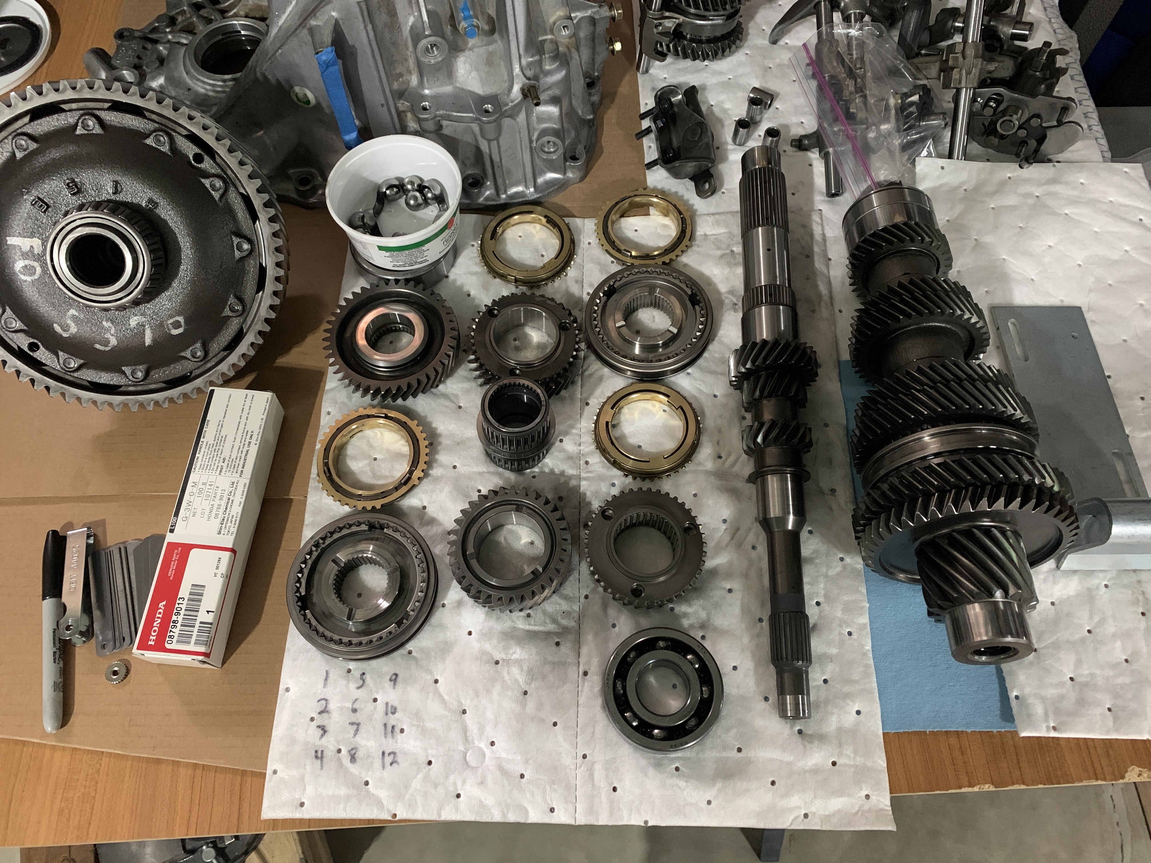
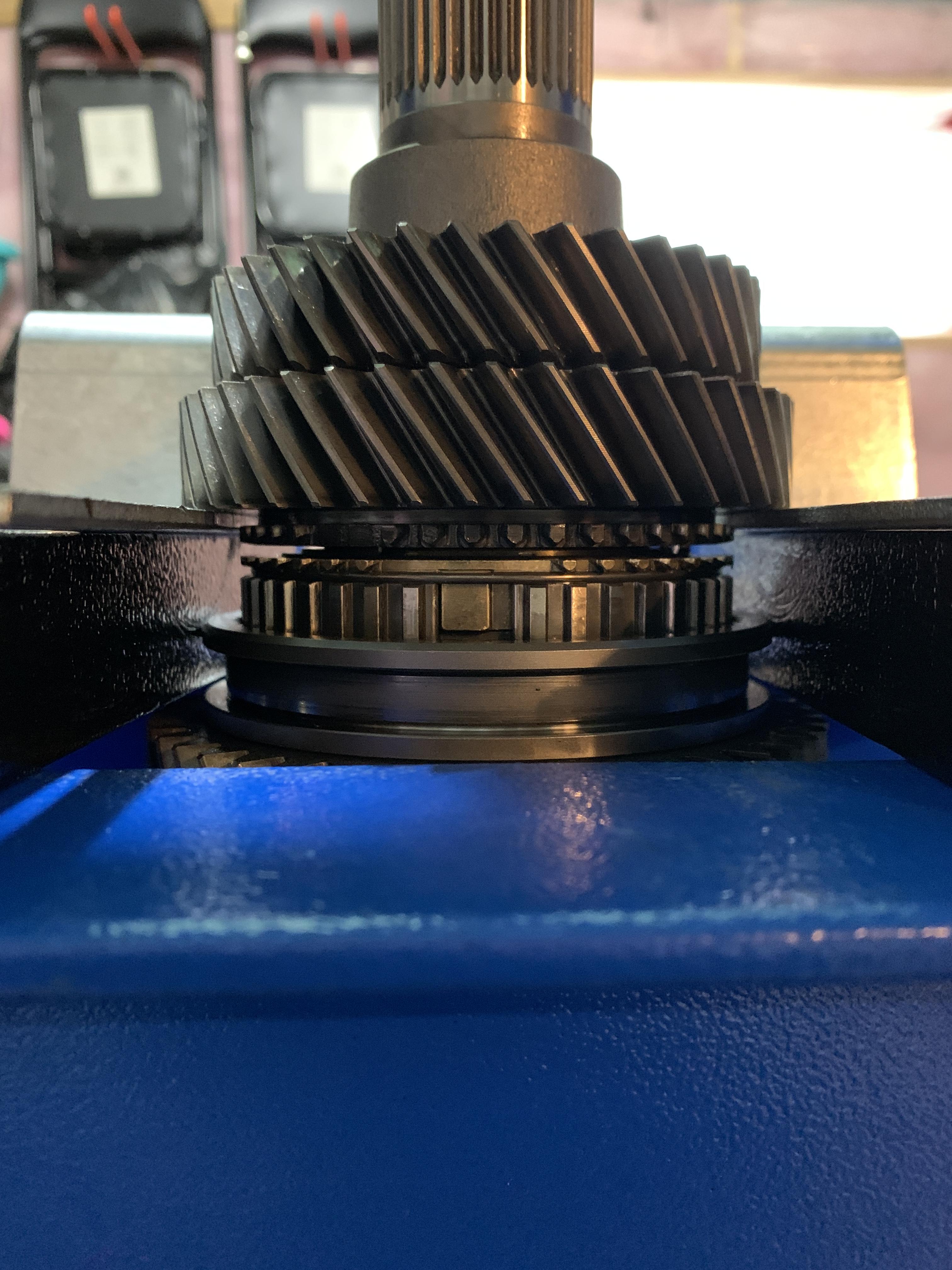
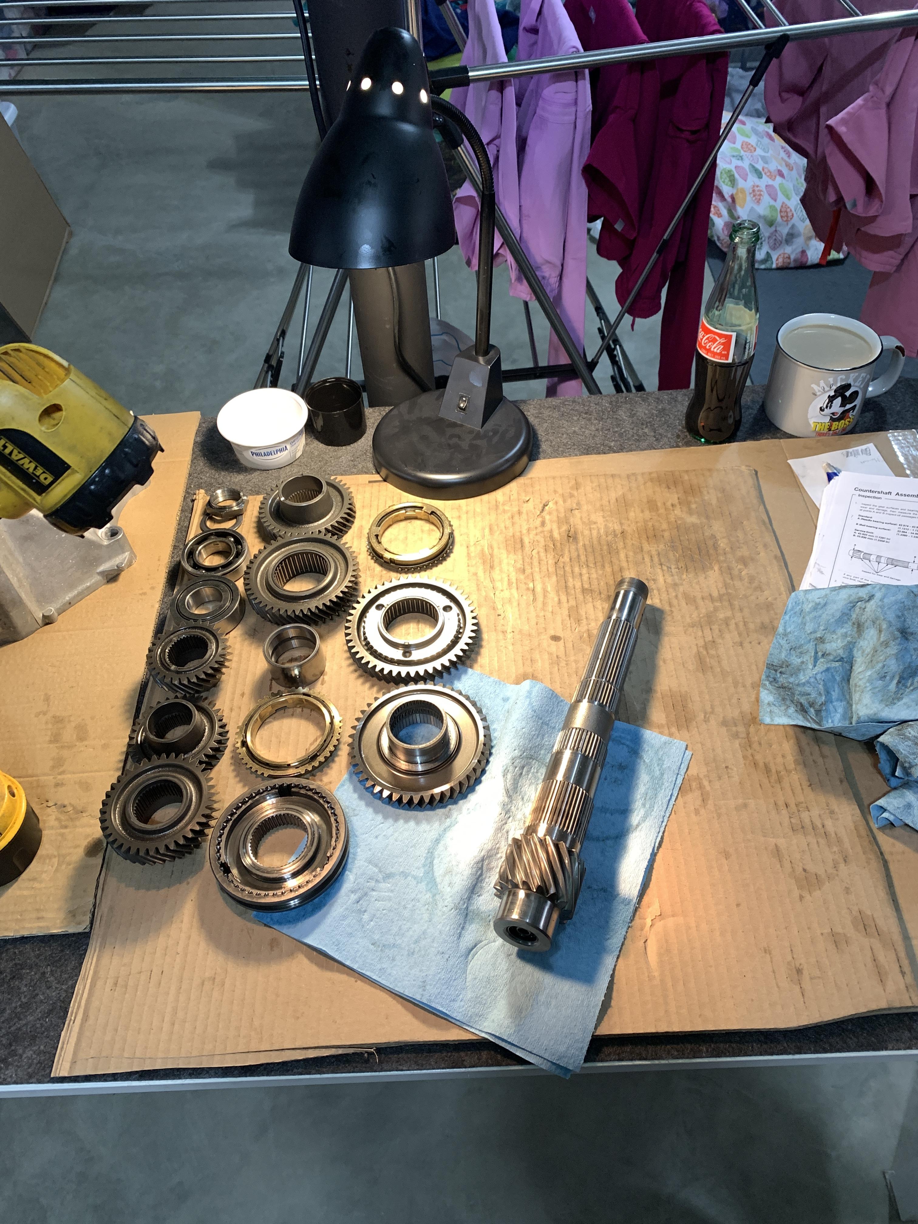
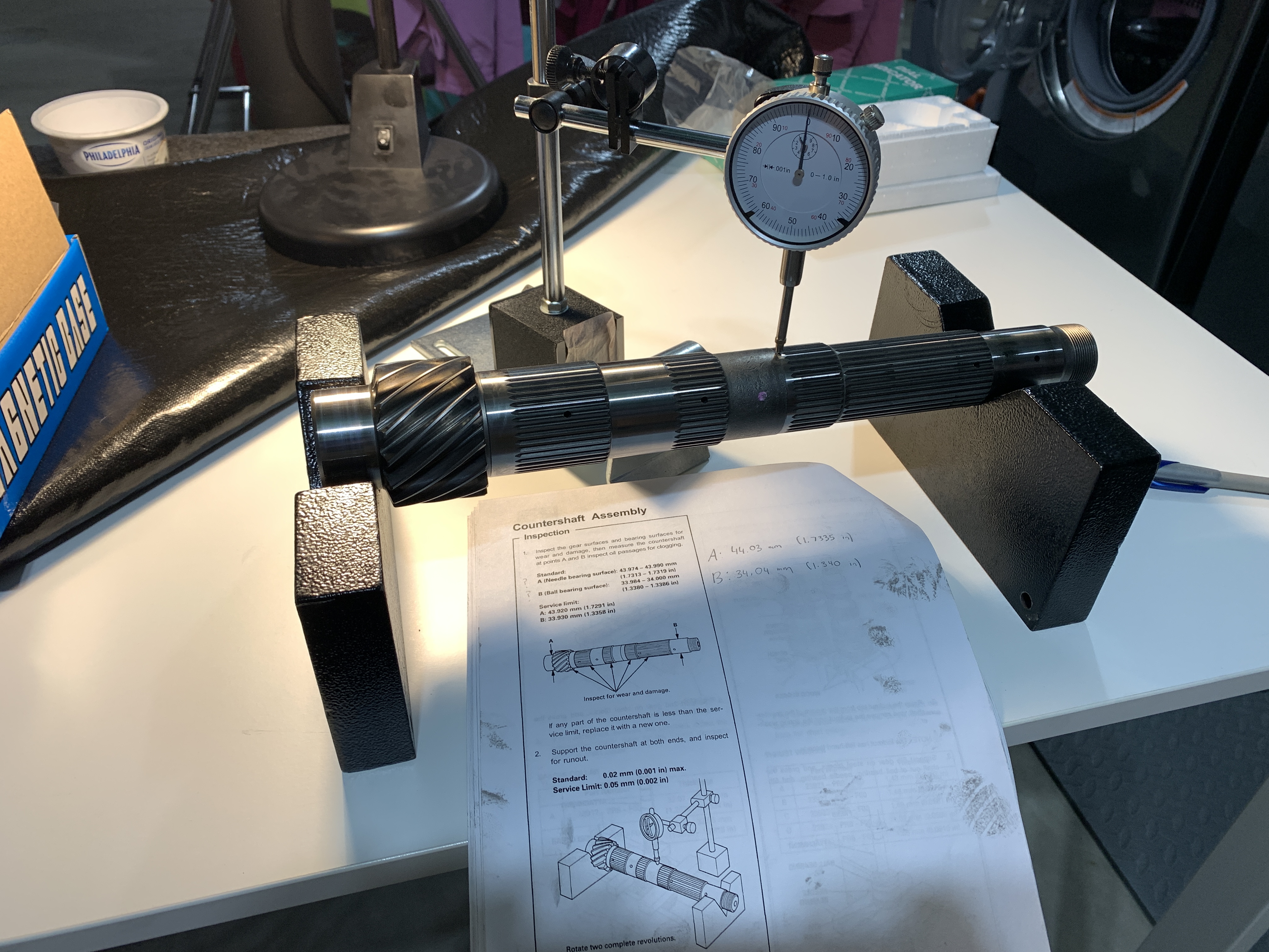
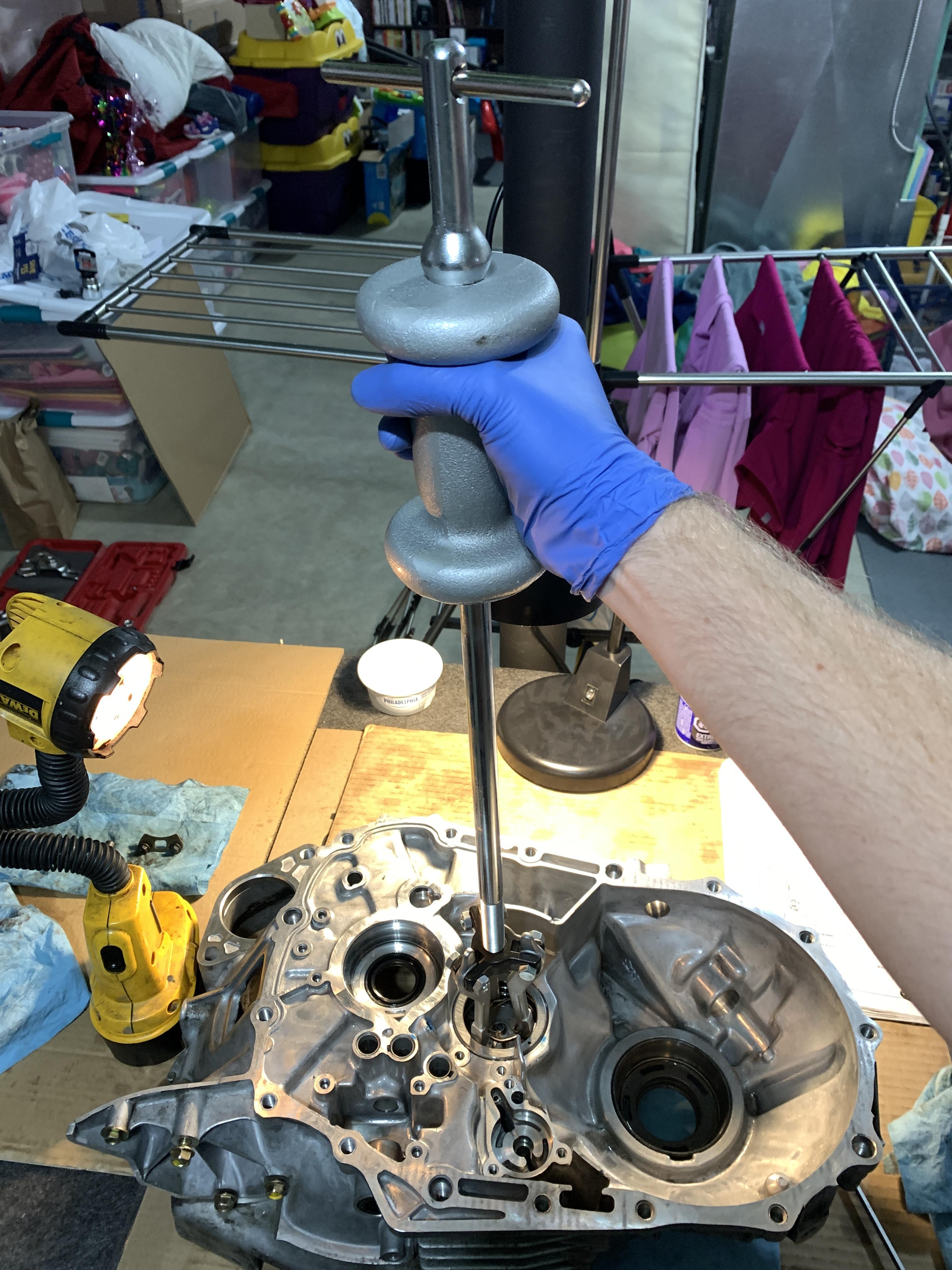
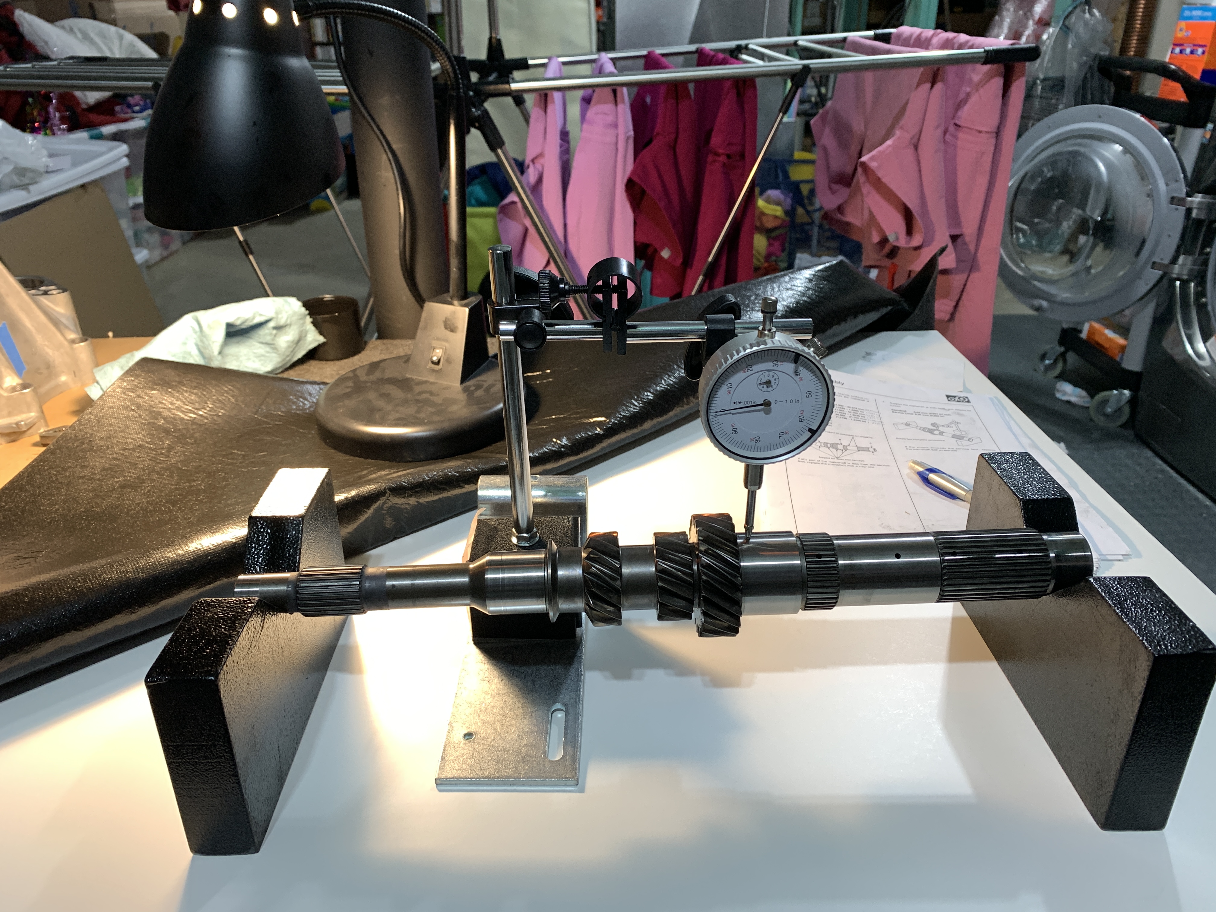
Now for some crossing of the fingers and trying to replicate the OEM setup as best I could for measuring shaft runout. At first I had the dial gauge set up on the cardboard and paper towels but I was getting strange movements. Once I put the setup on the flat table the readings settled down.
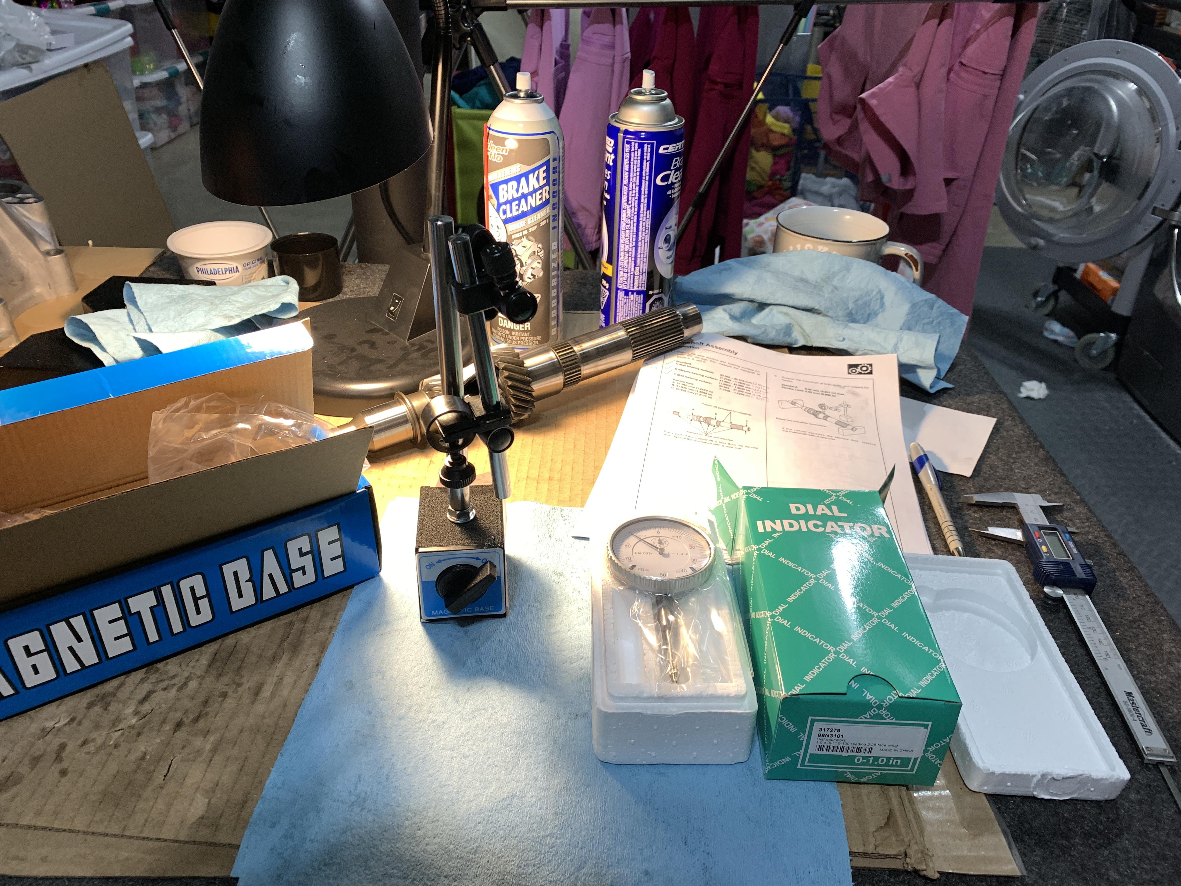
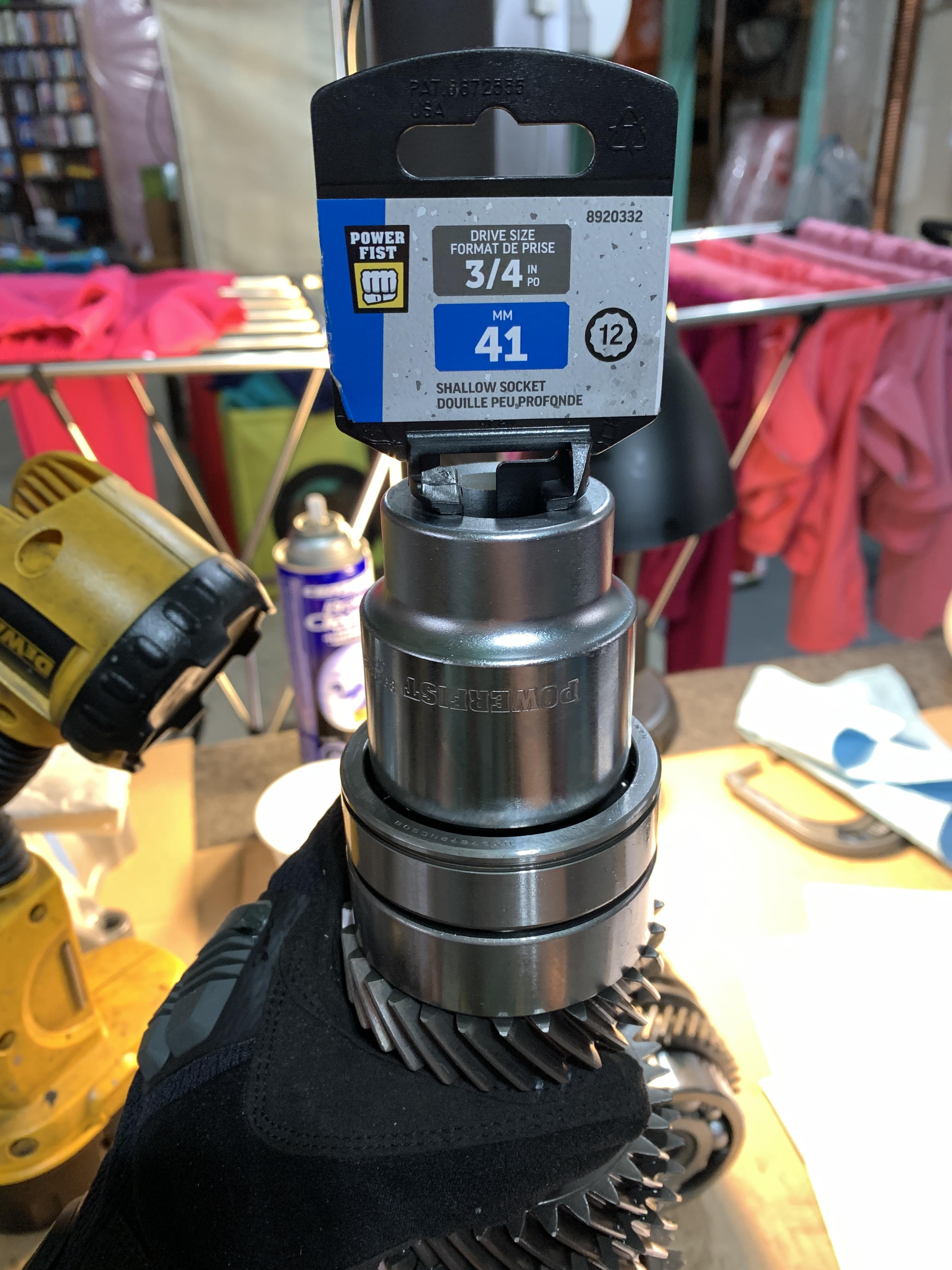
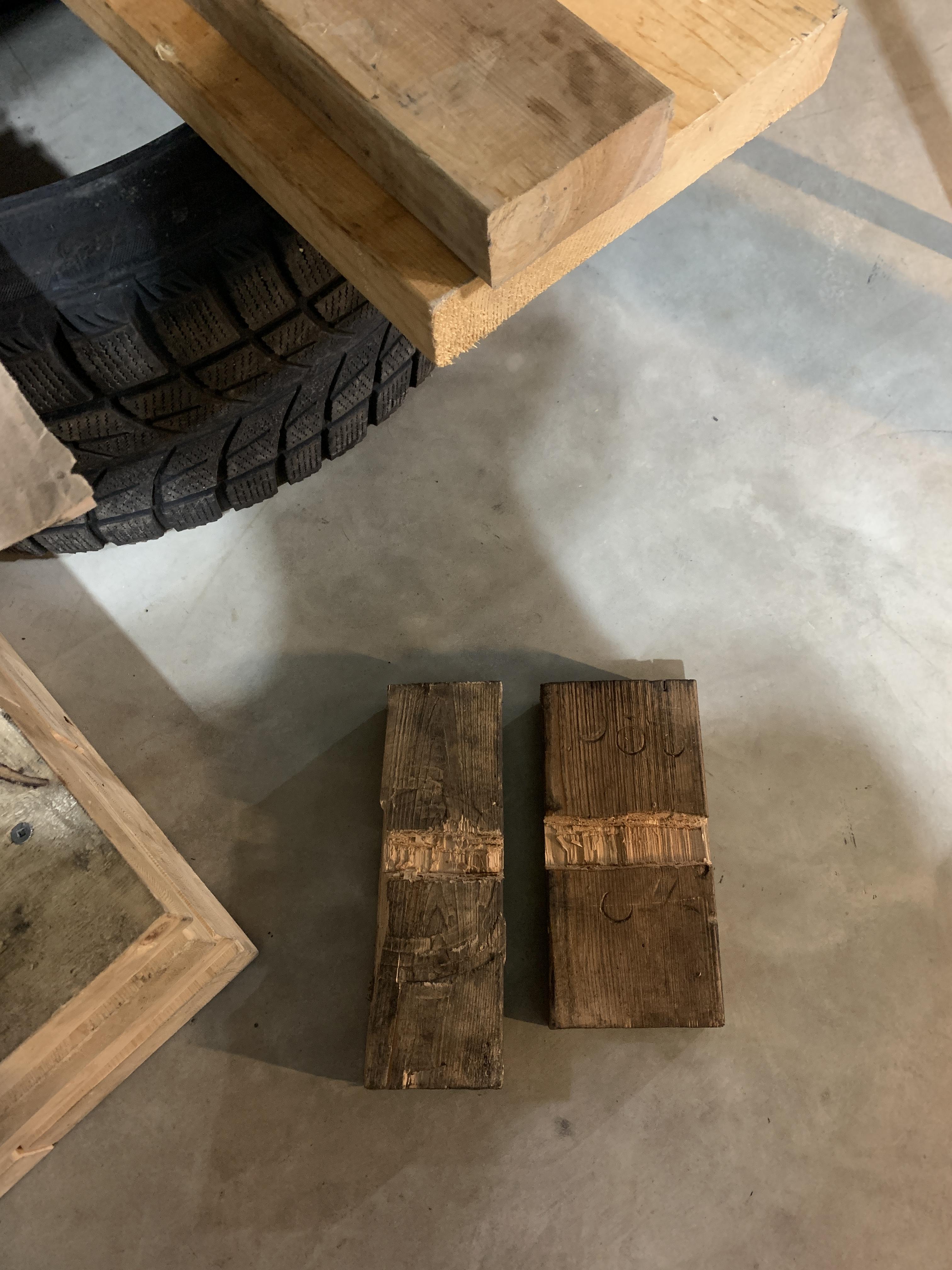
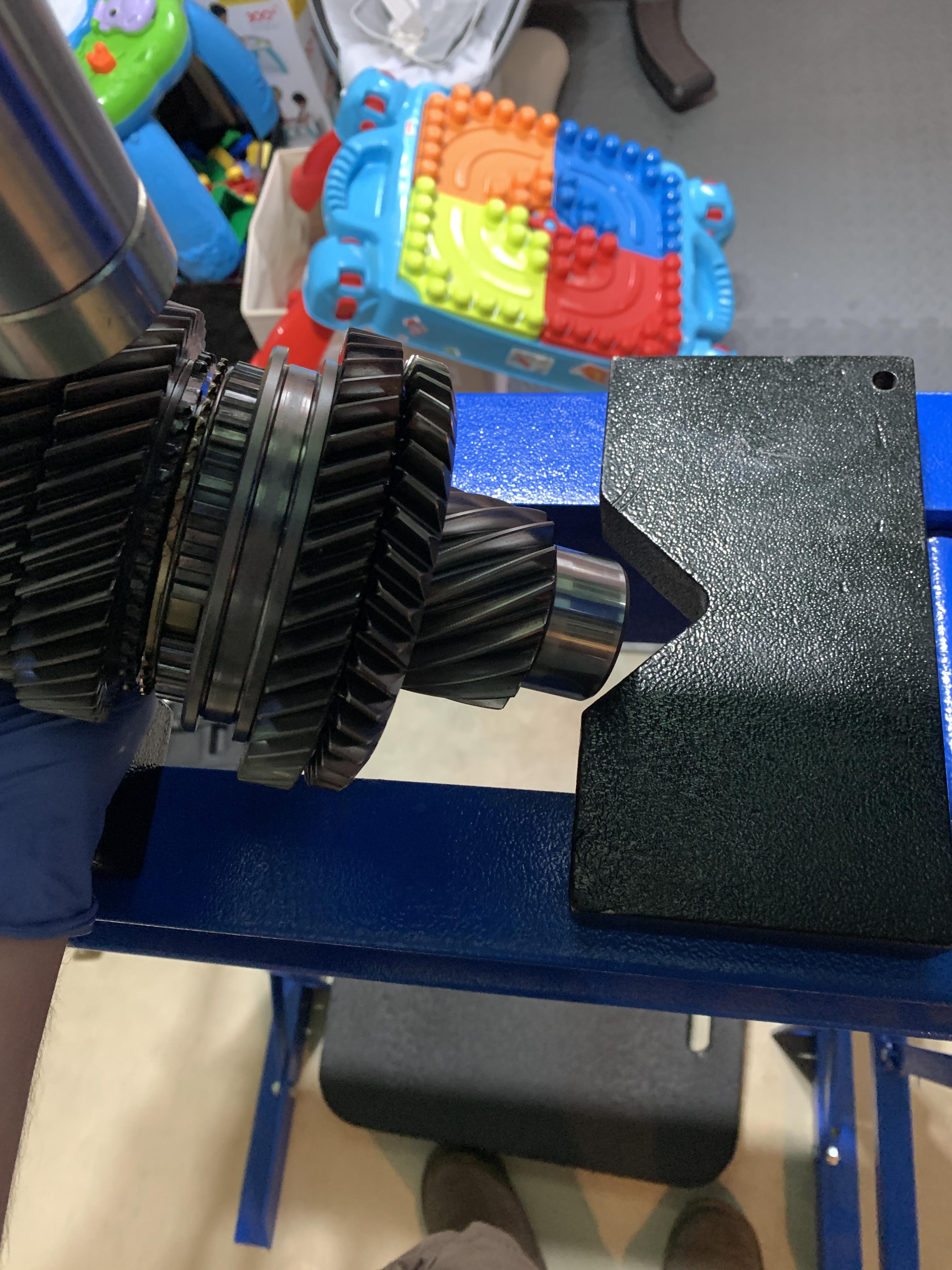
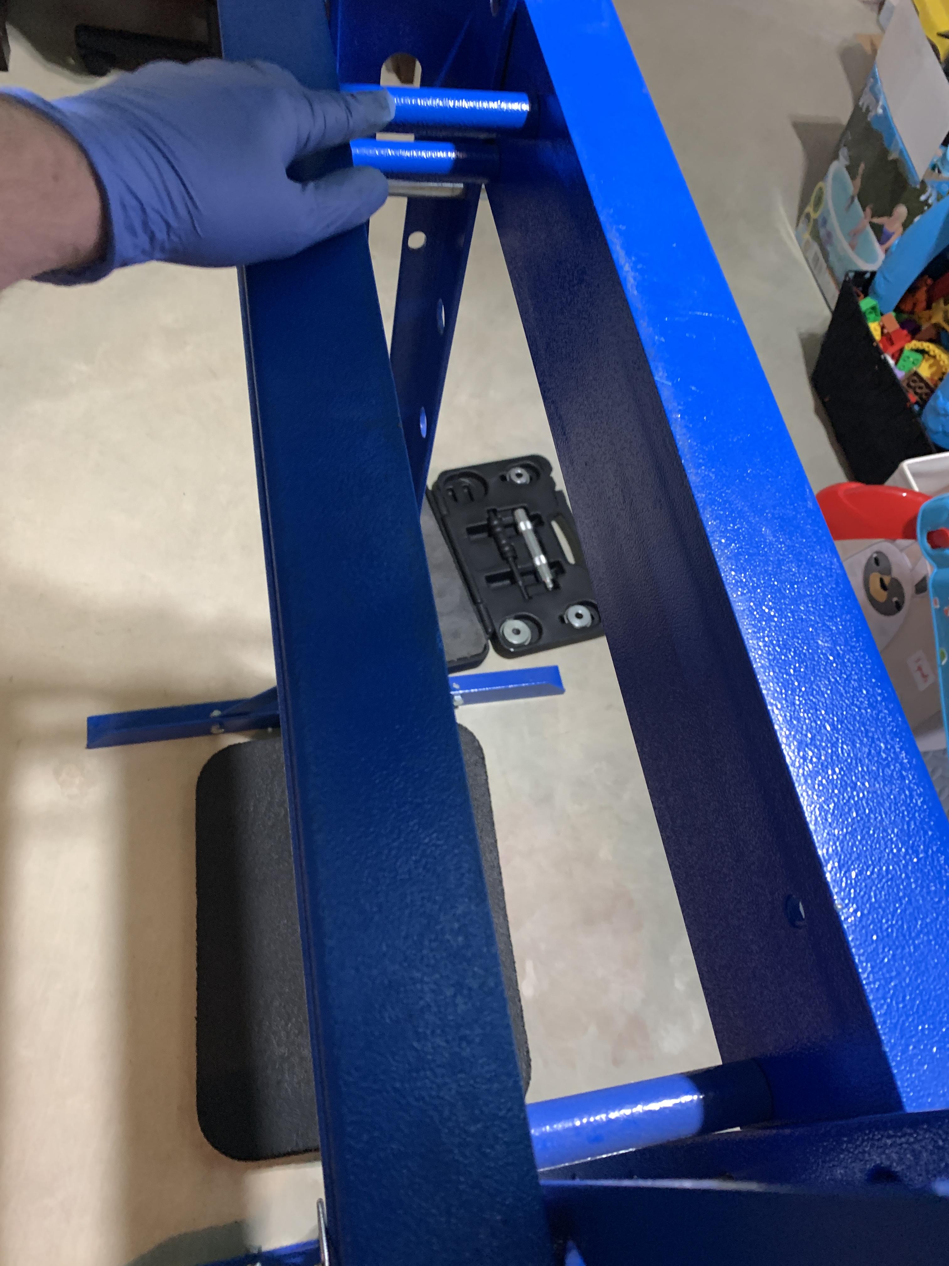
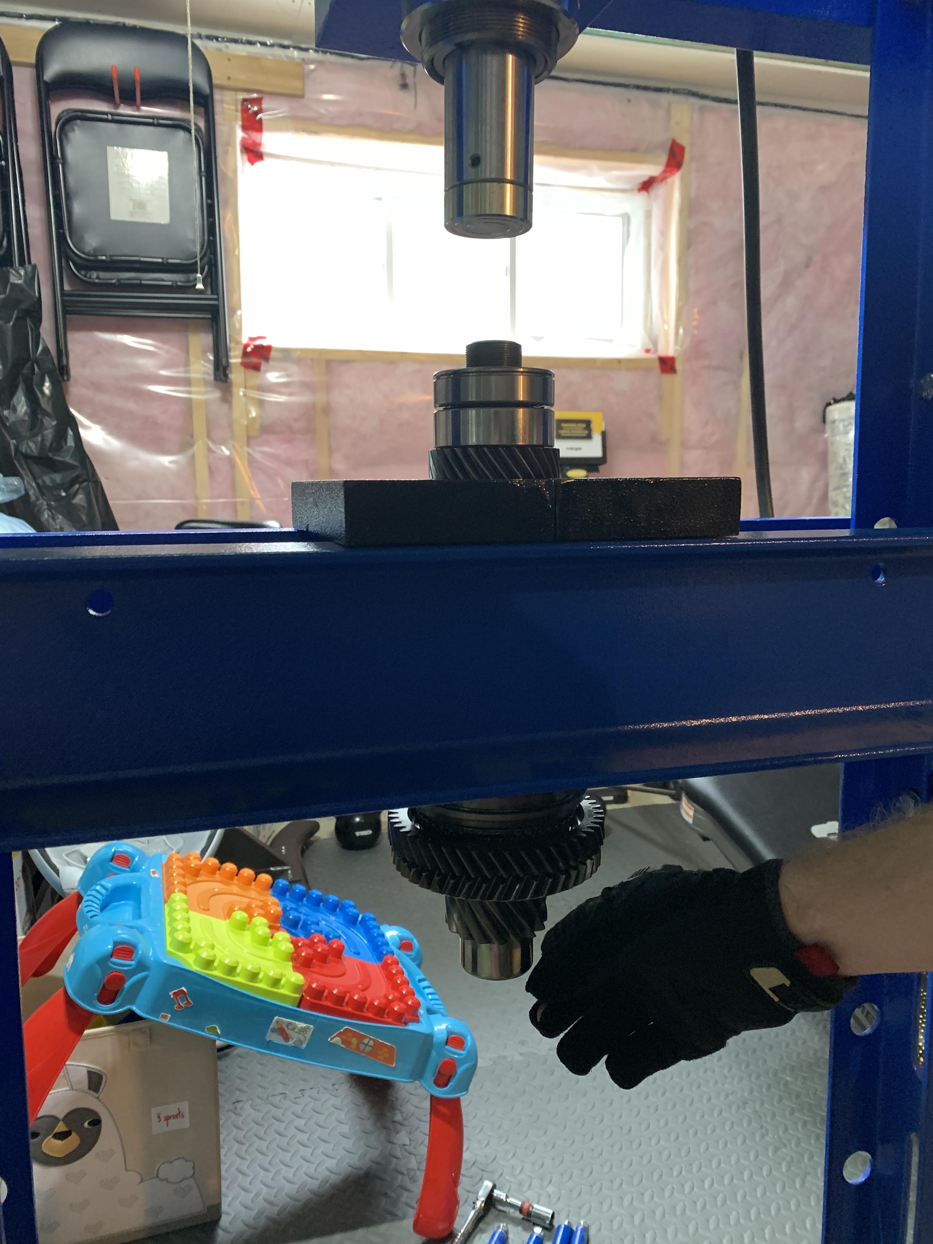
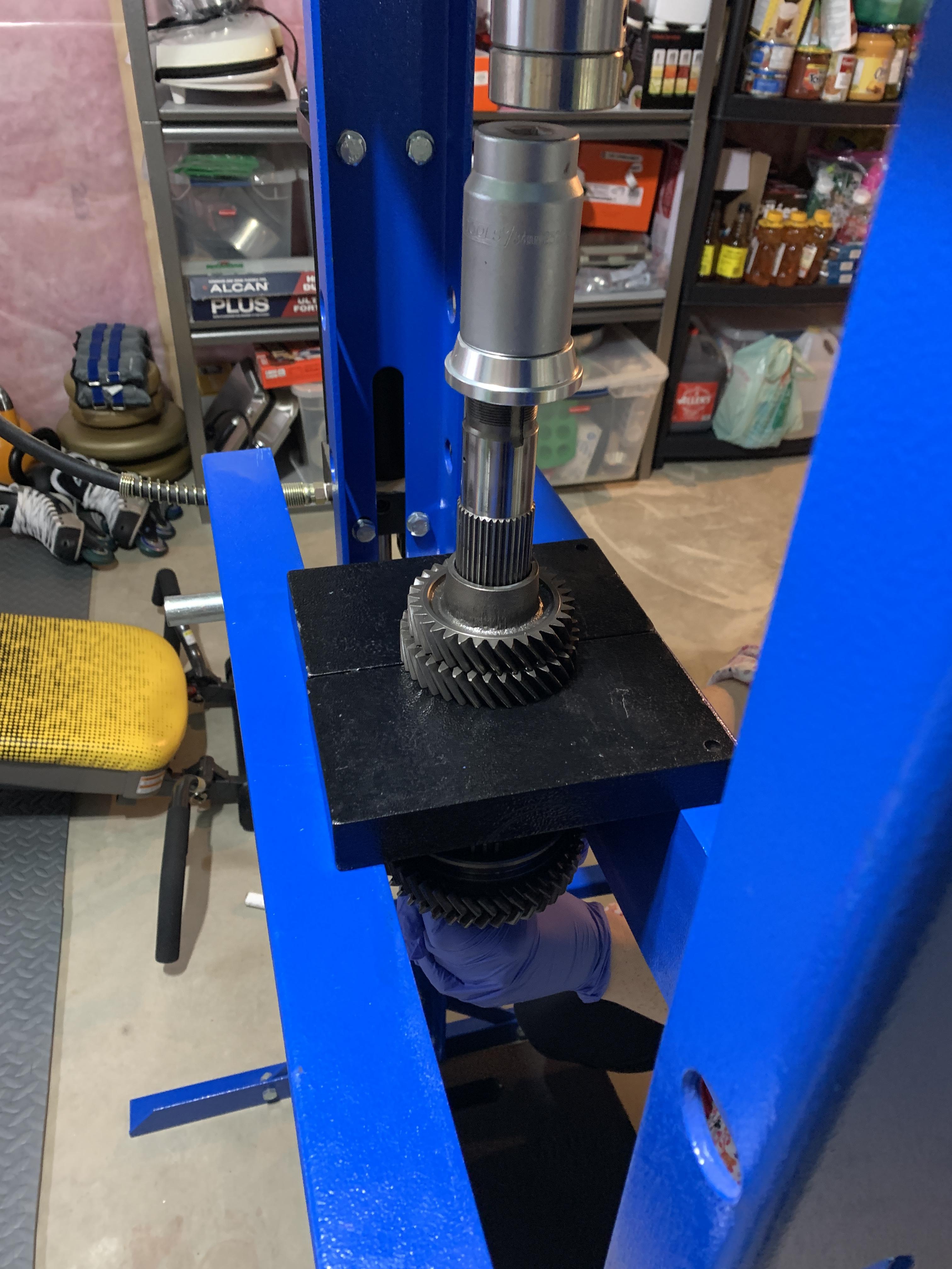
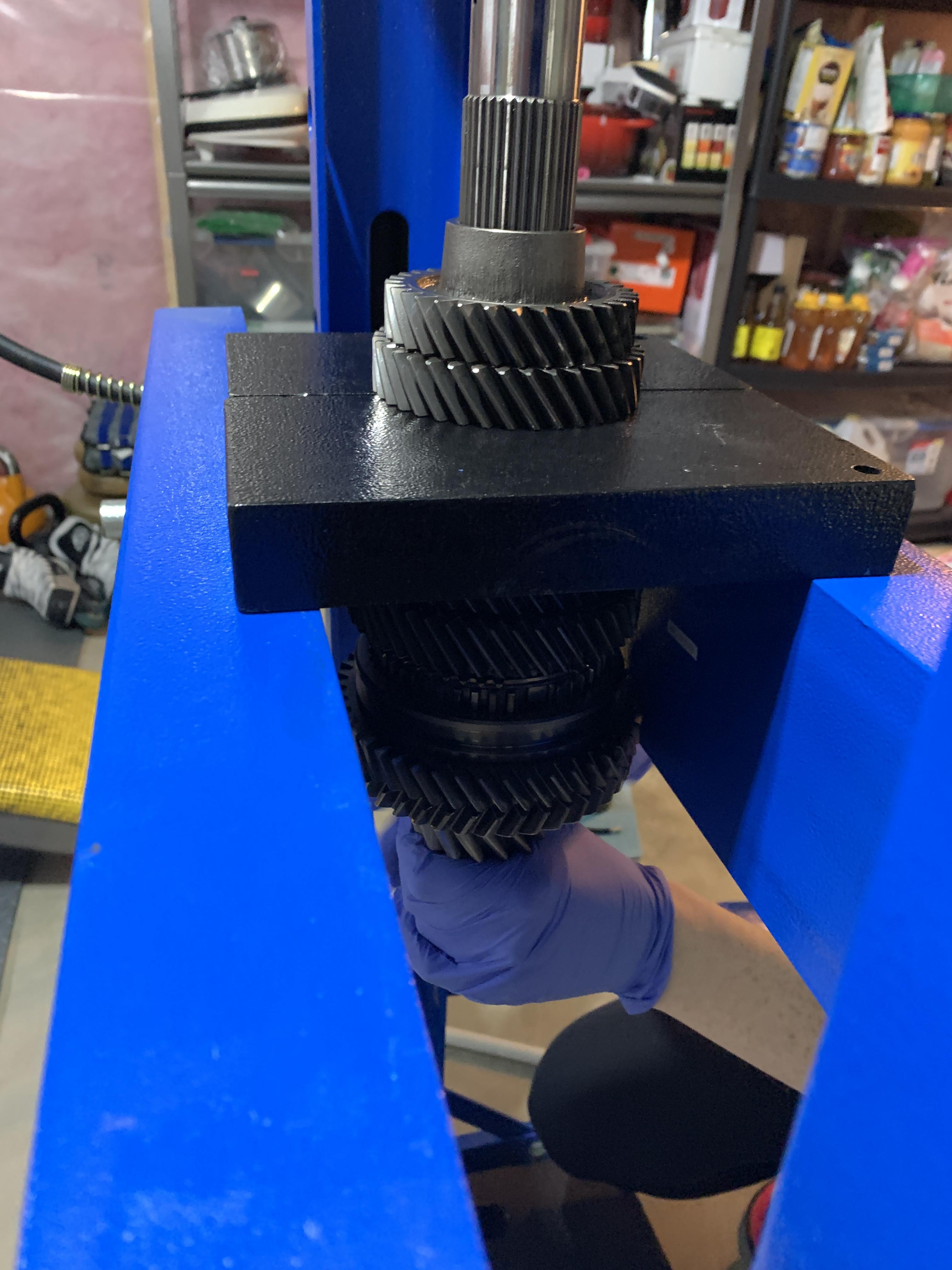
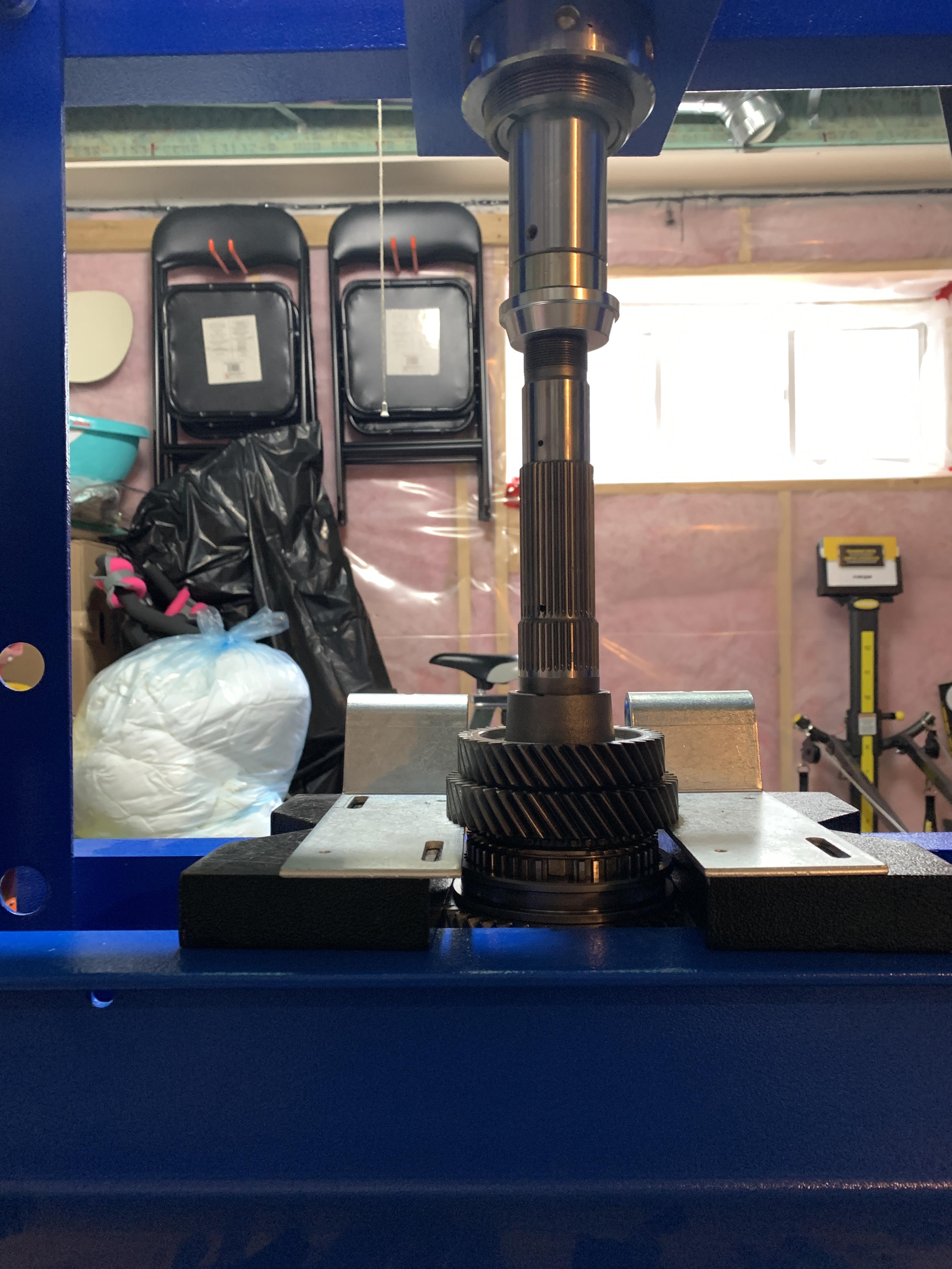
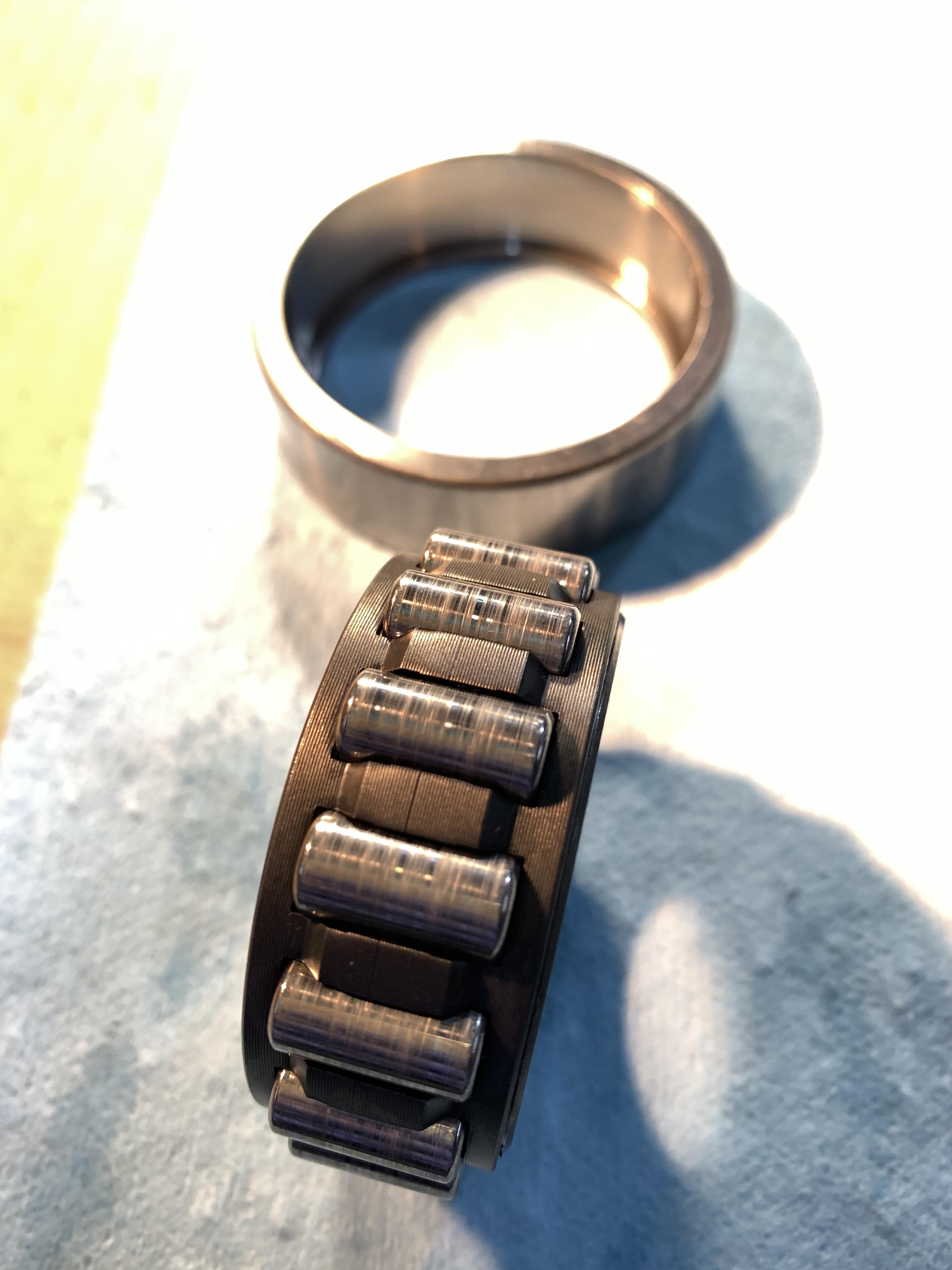
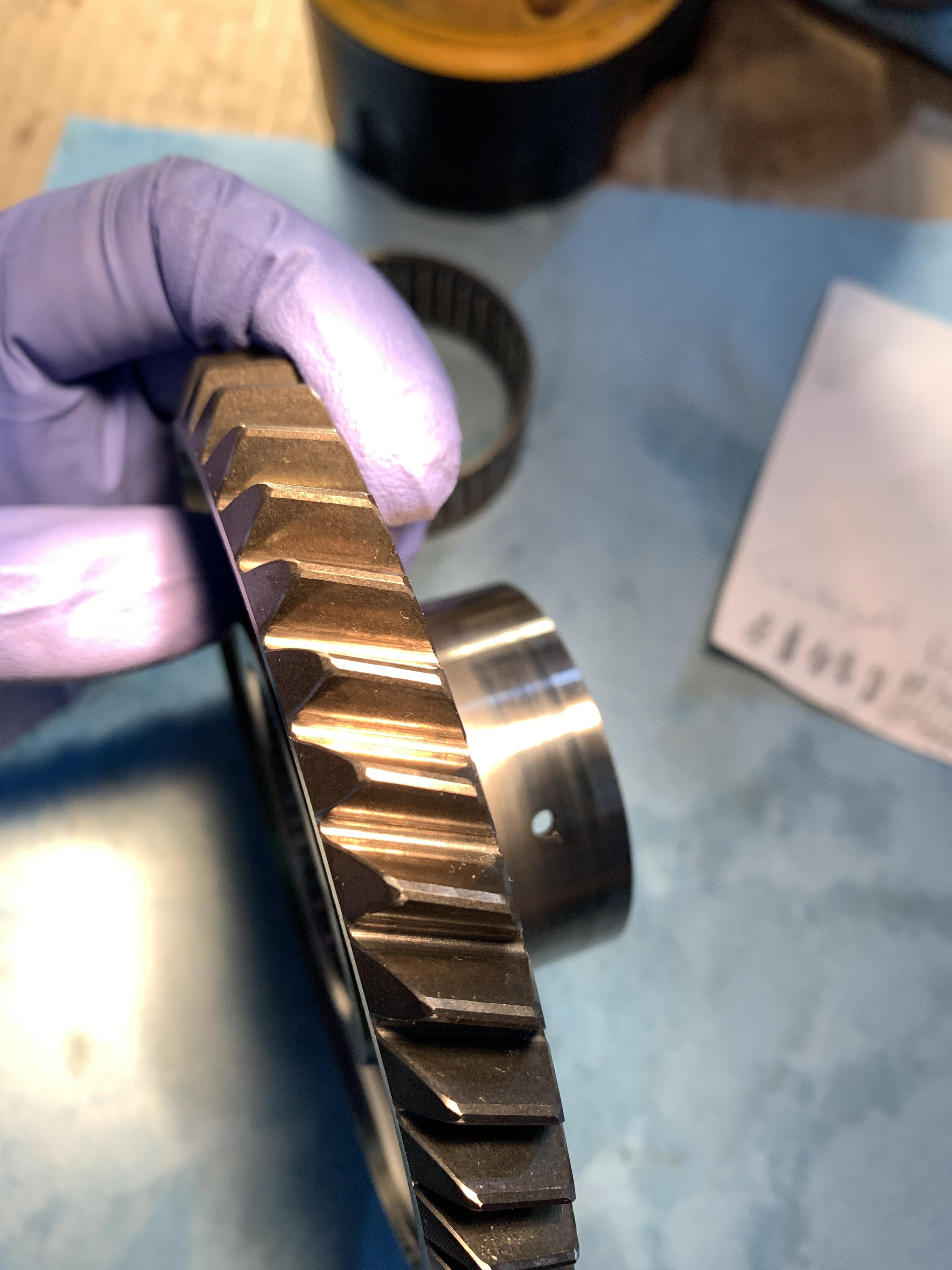
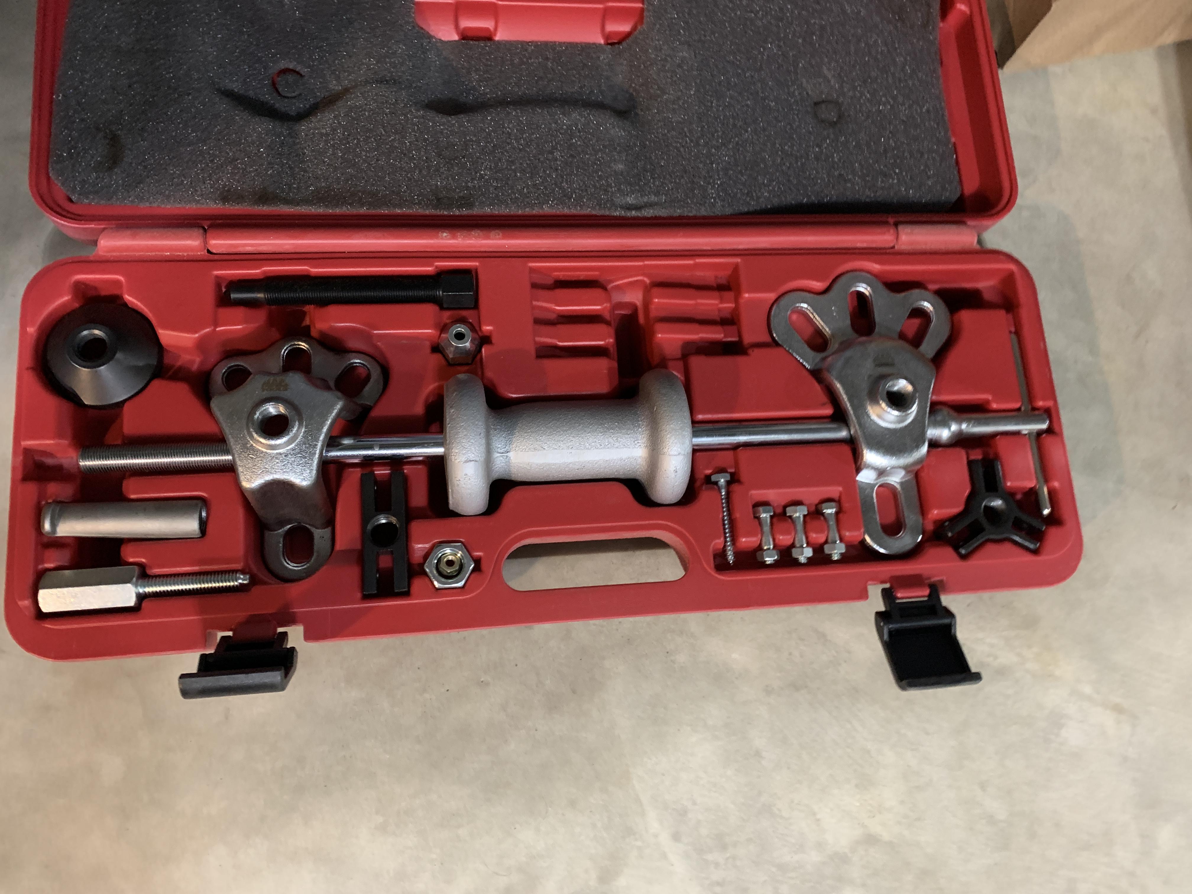
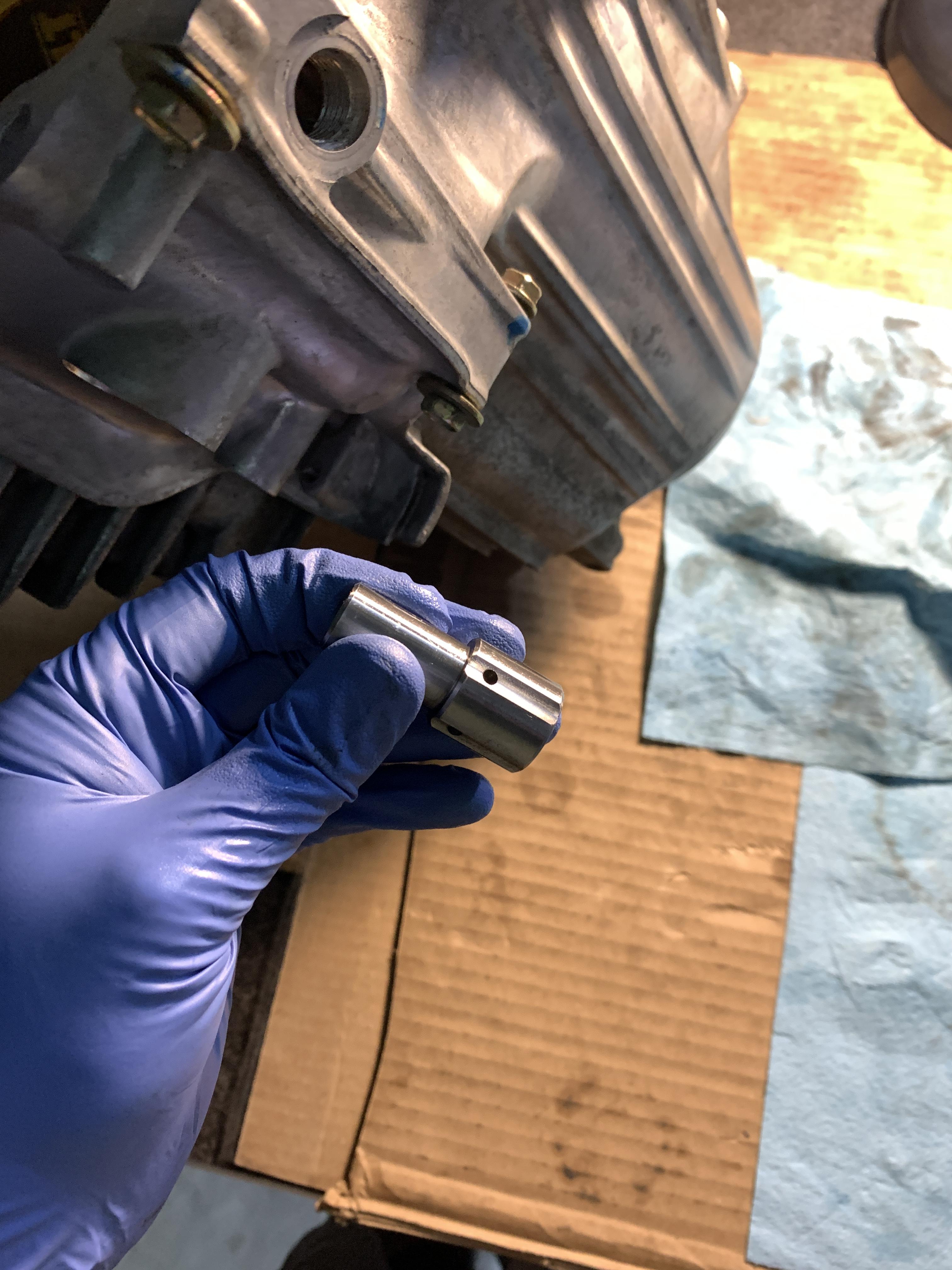
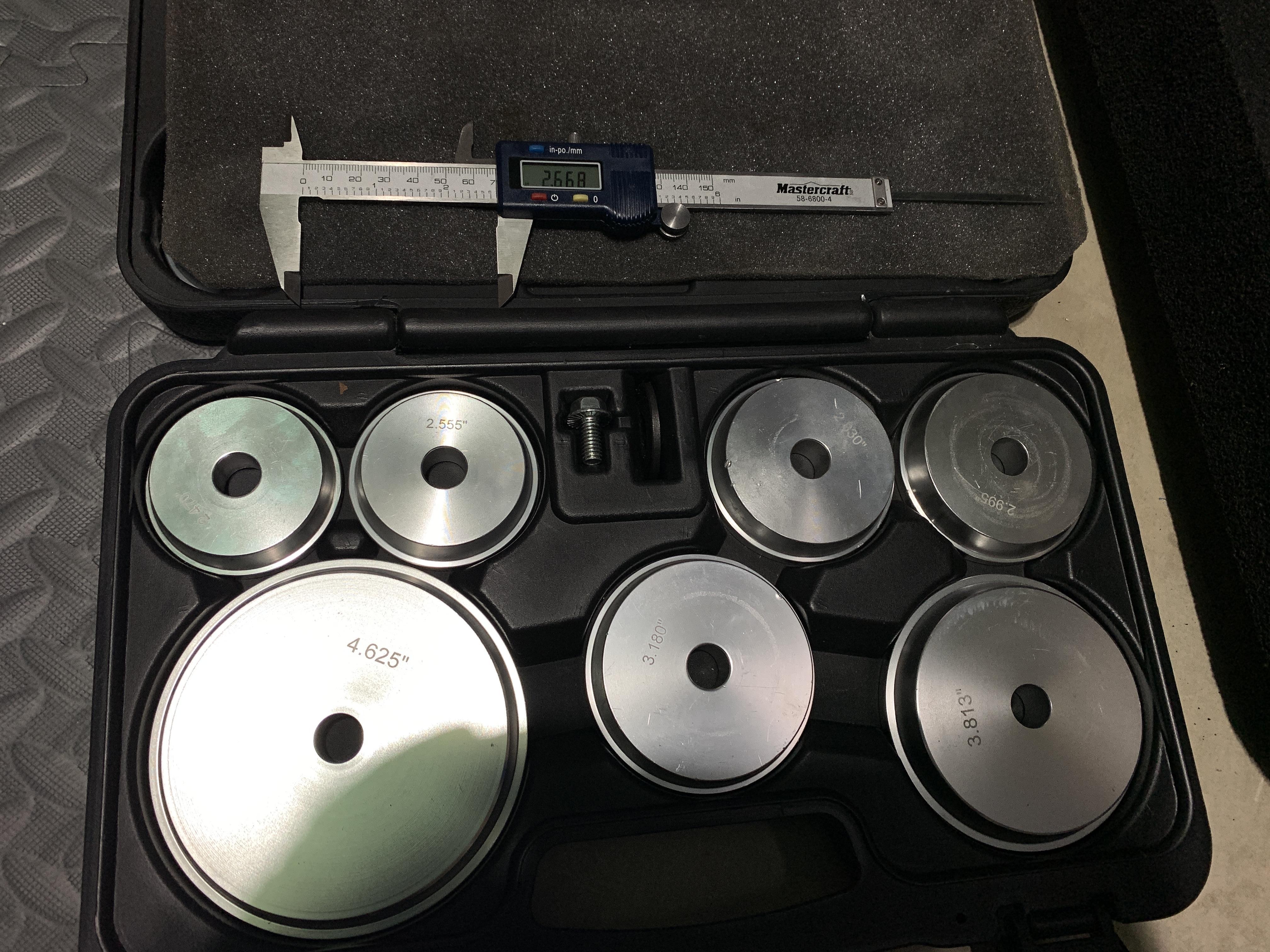
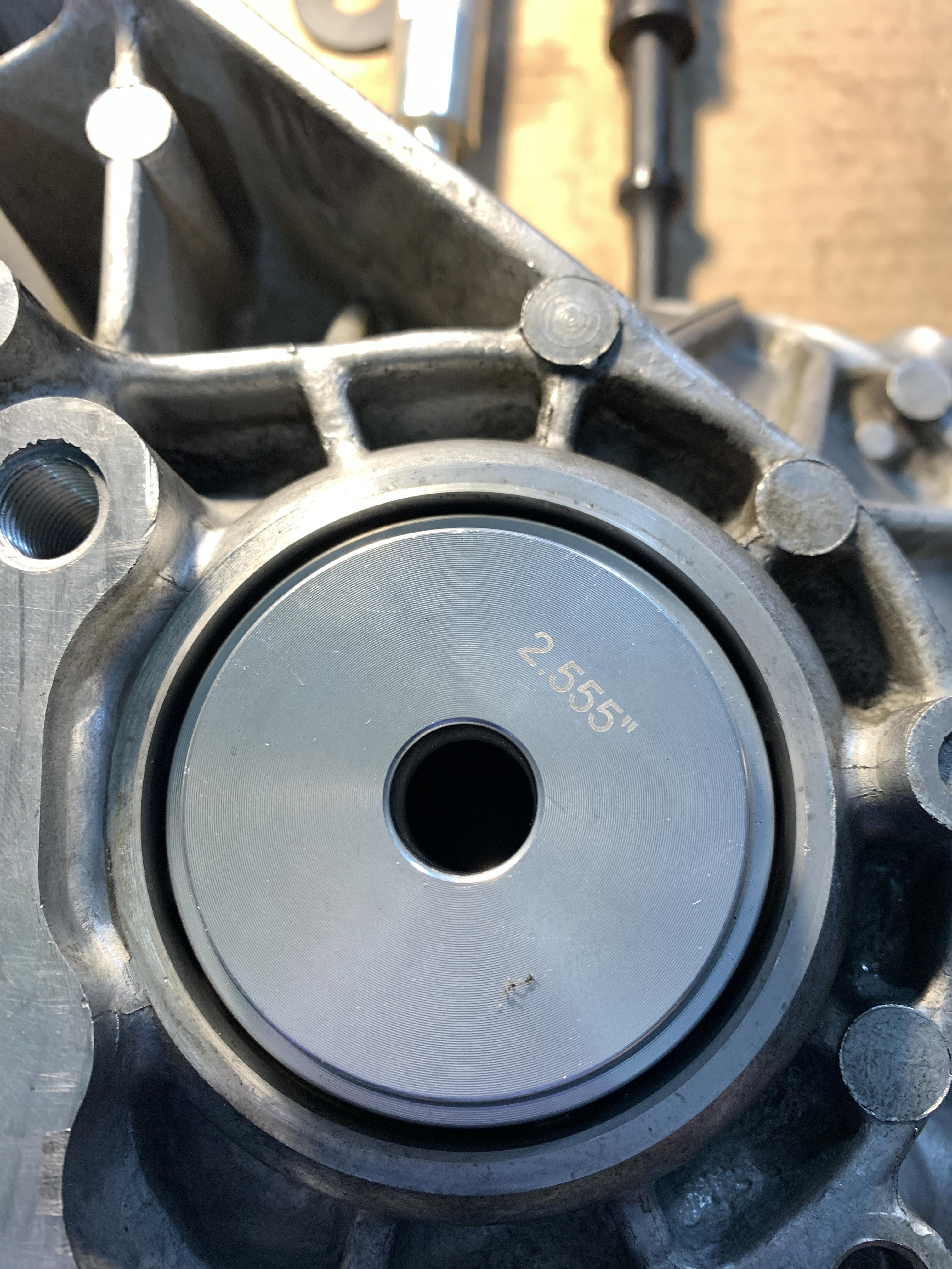
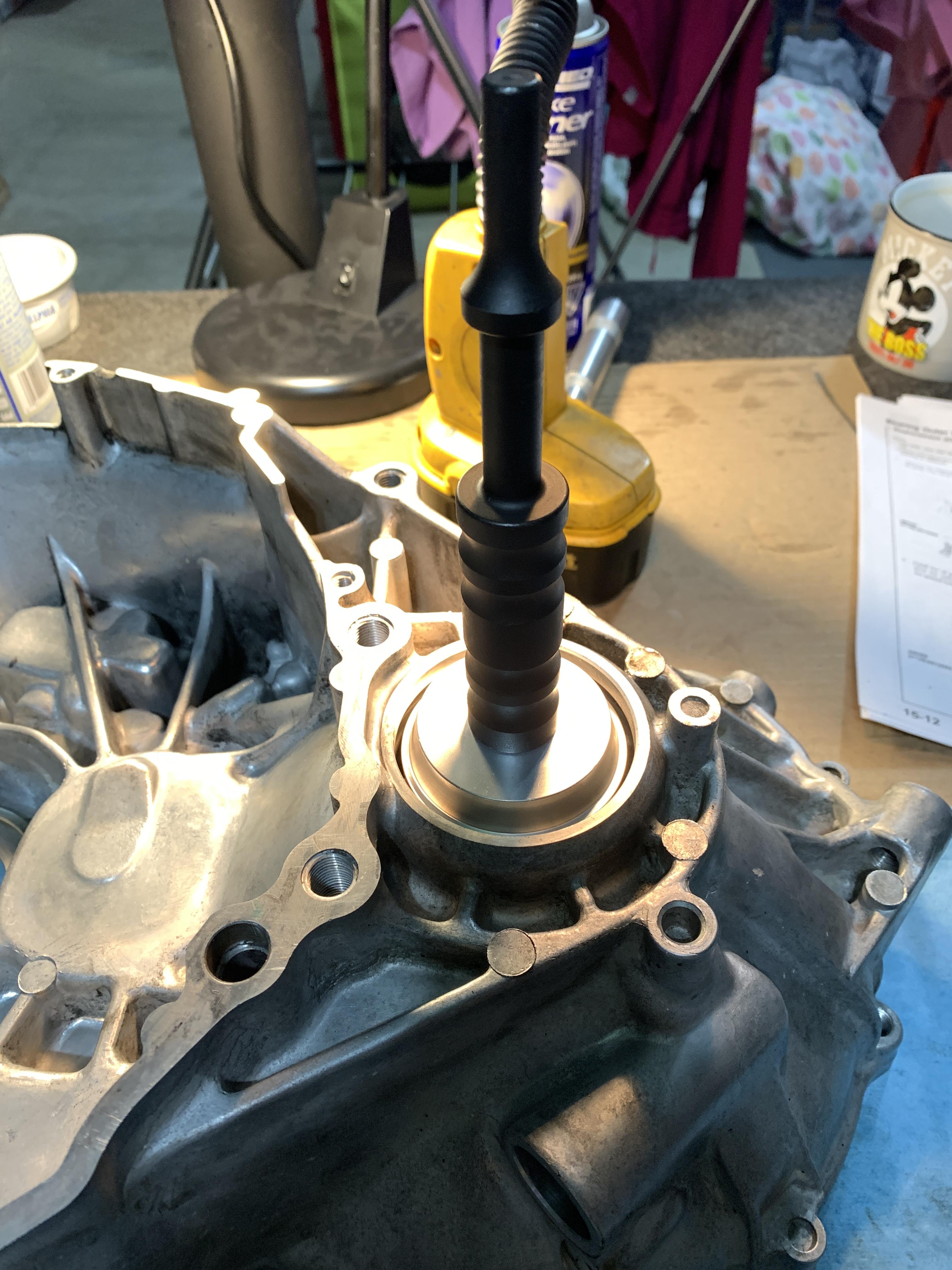
I used the press blocks to hold the shaft.
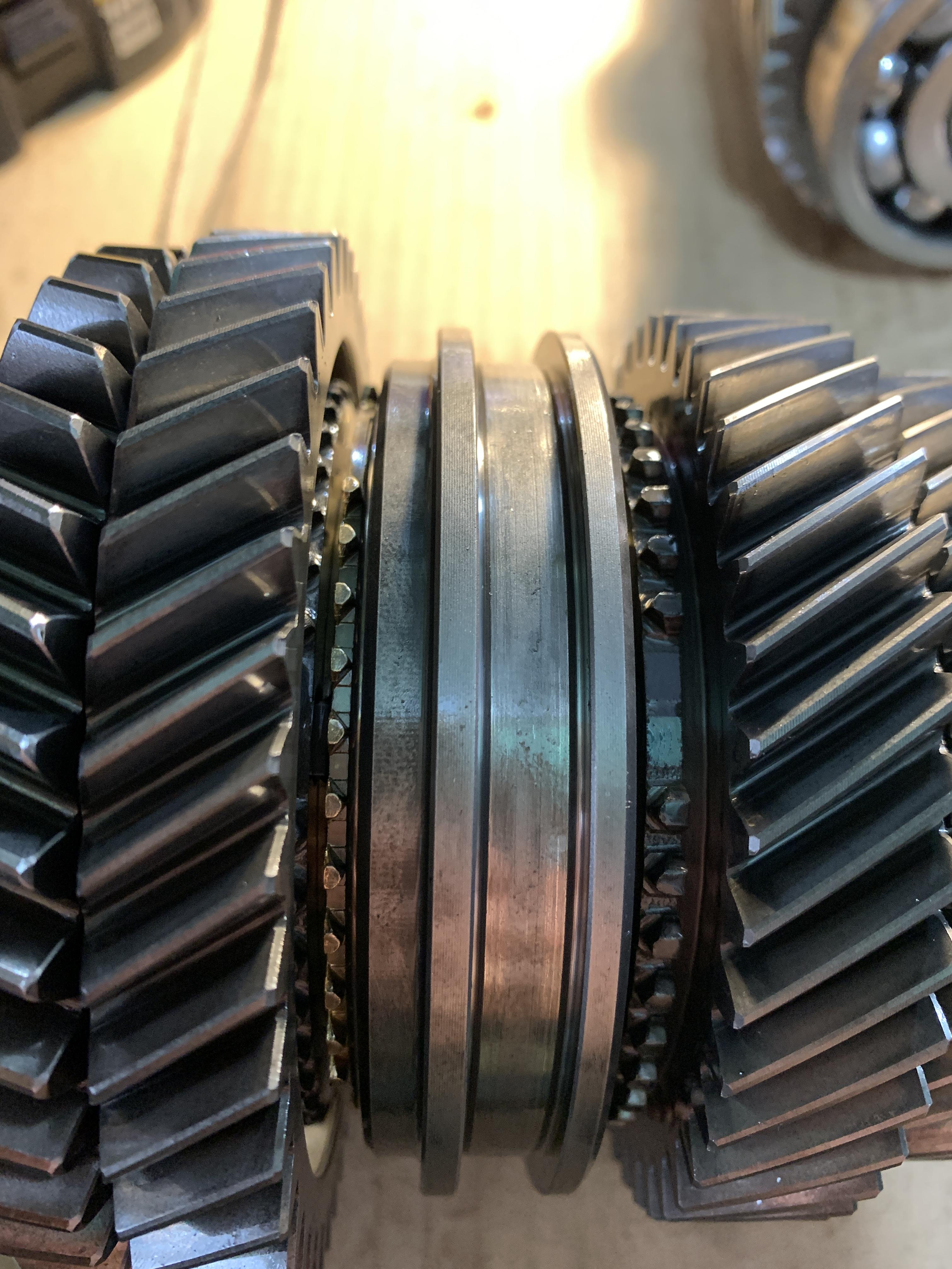
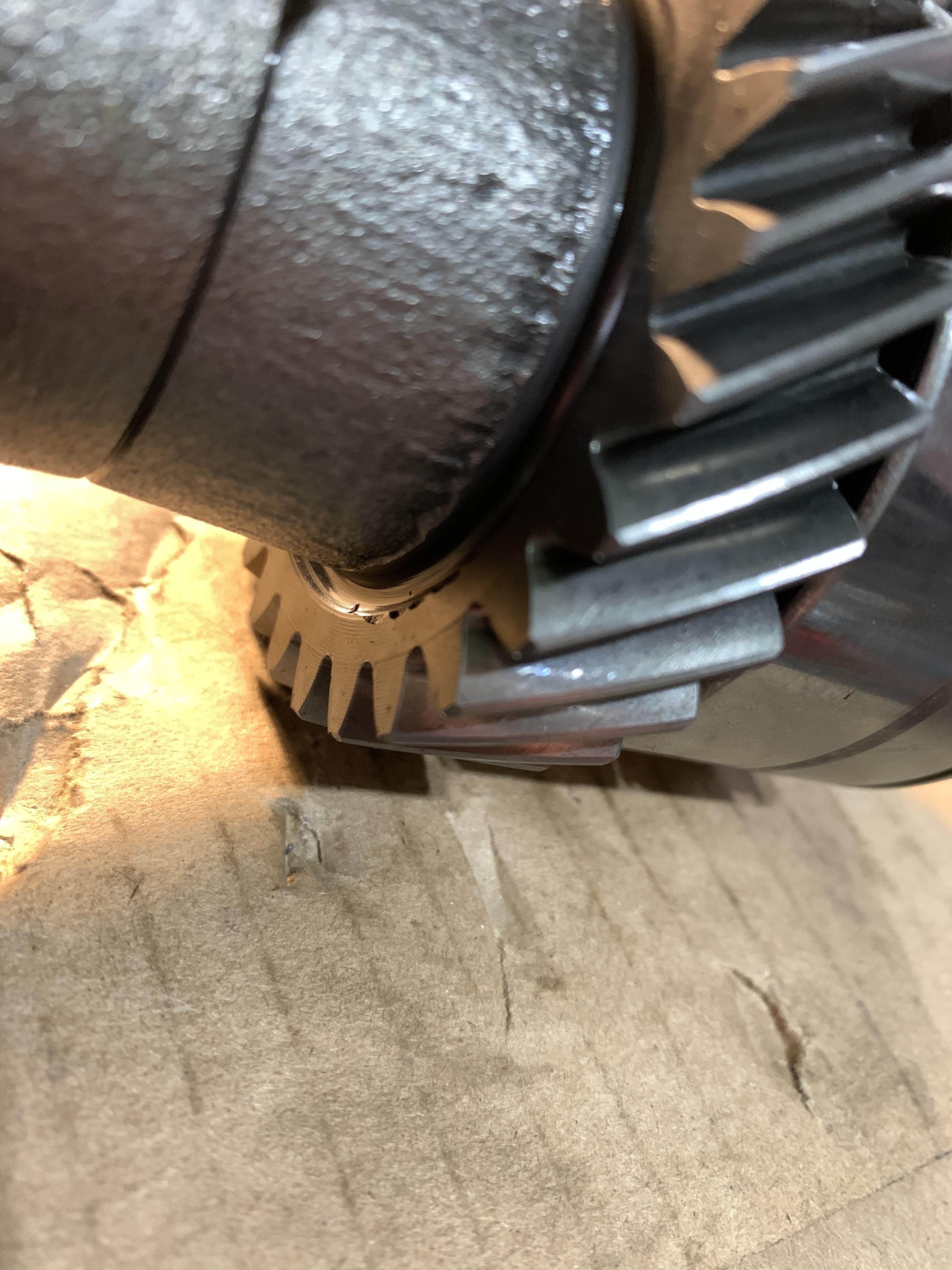
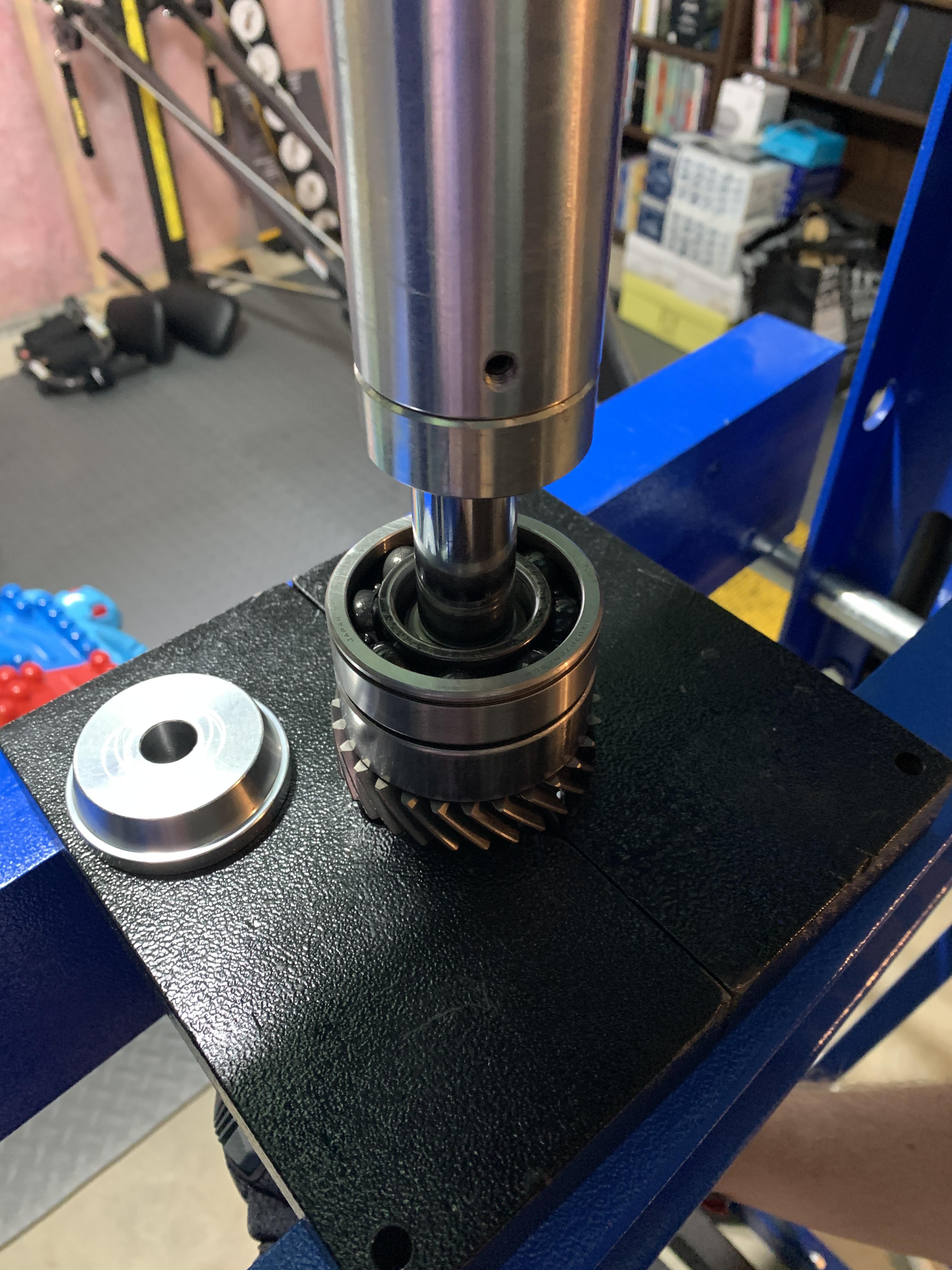
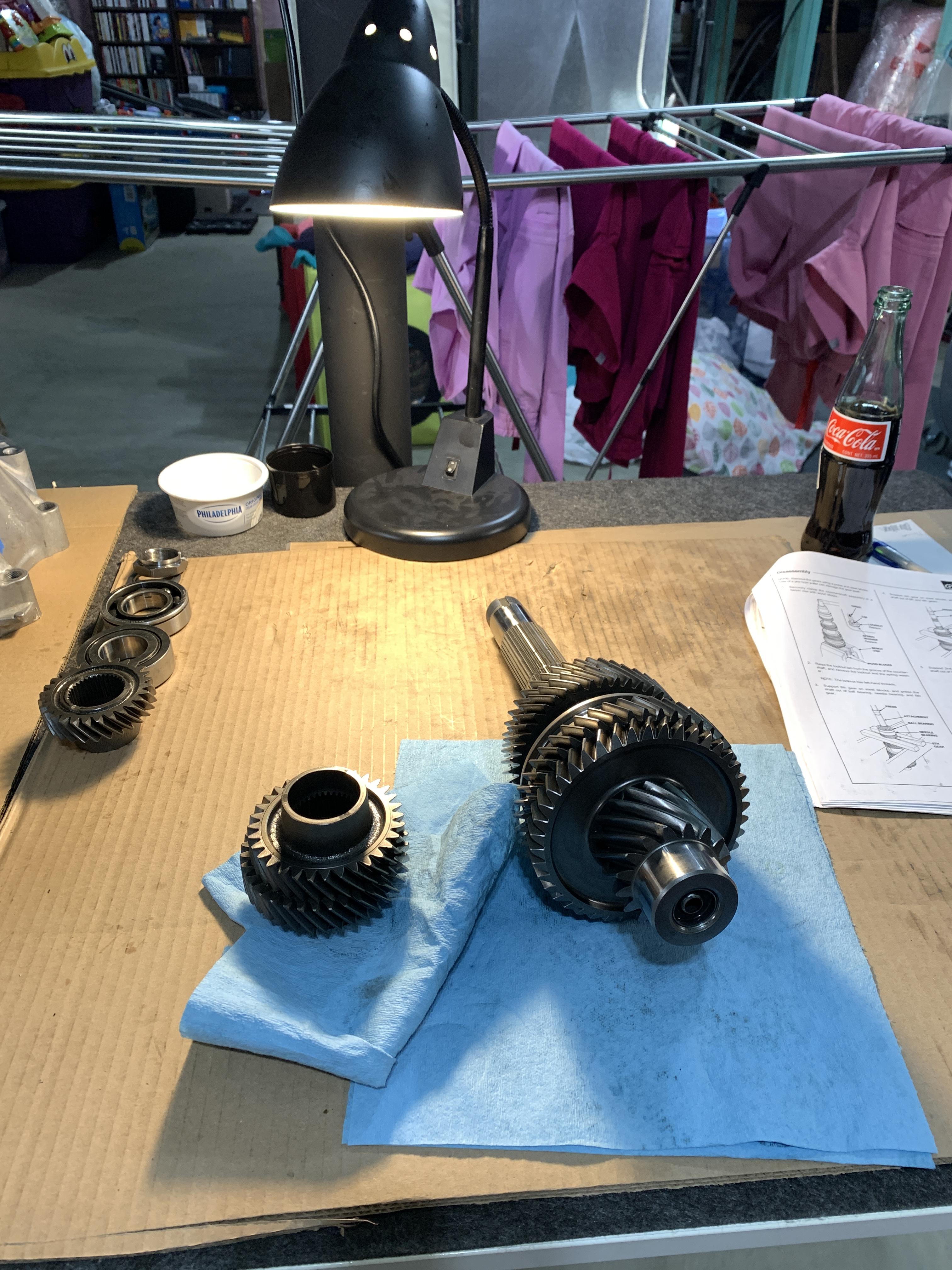
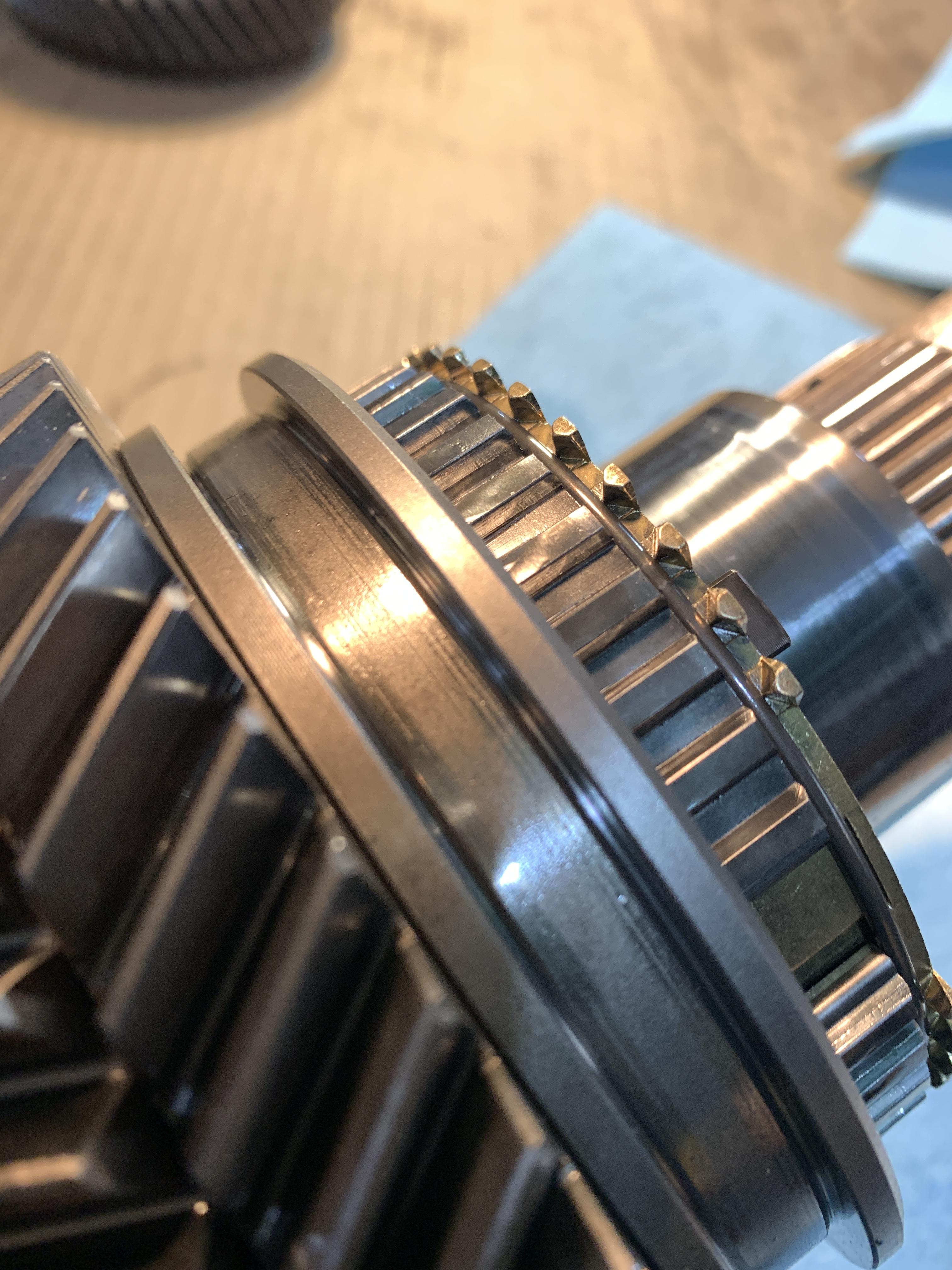
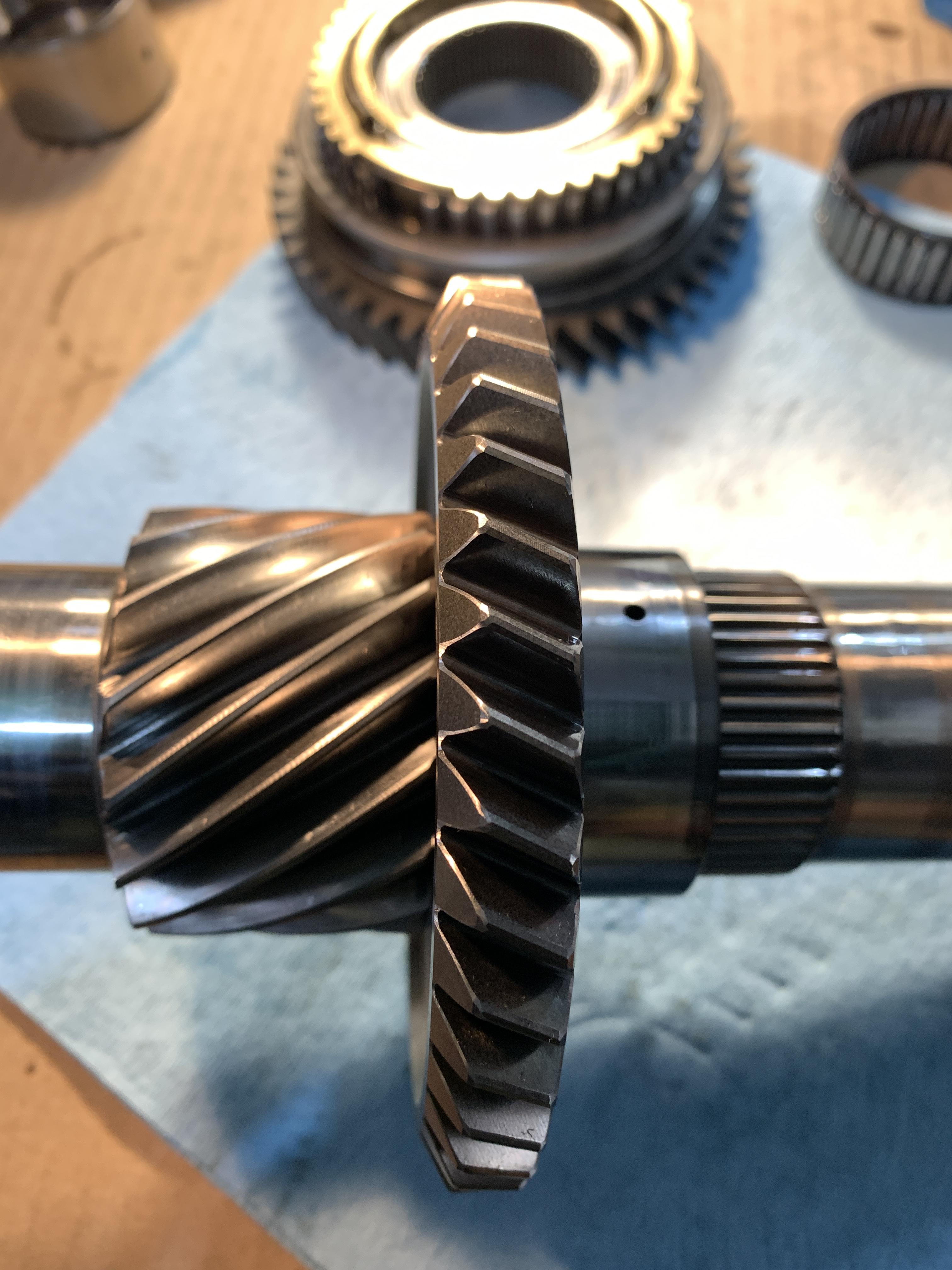
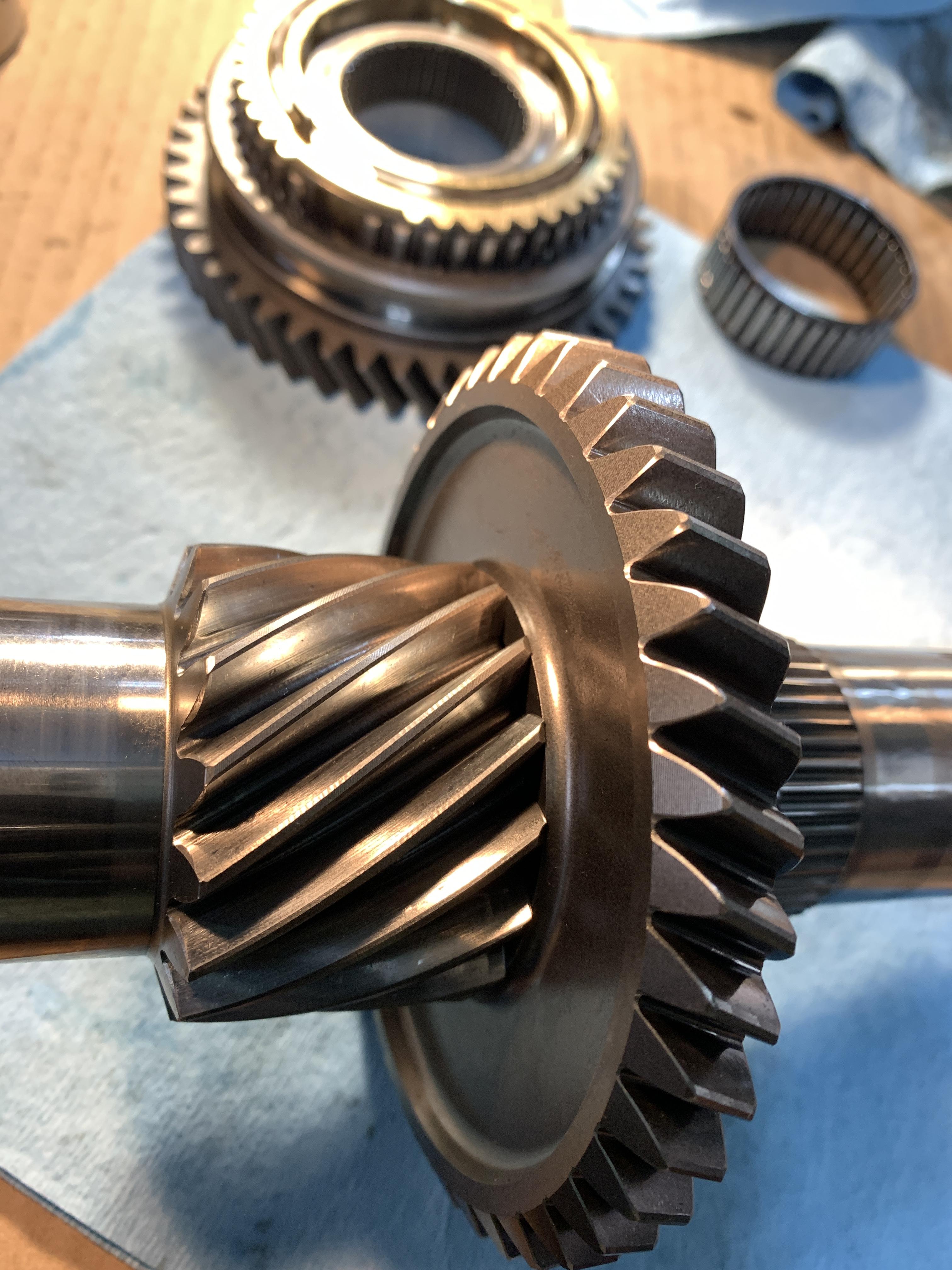
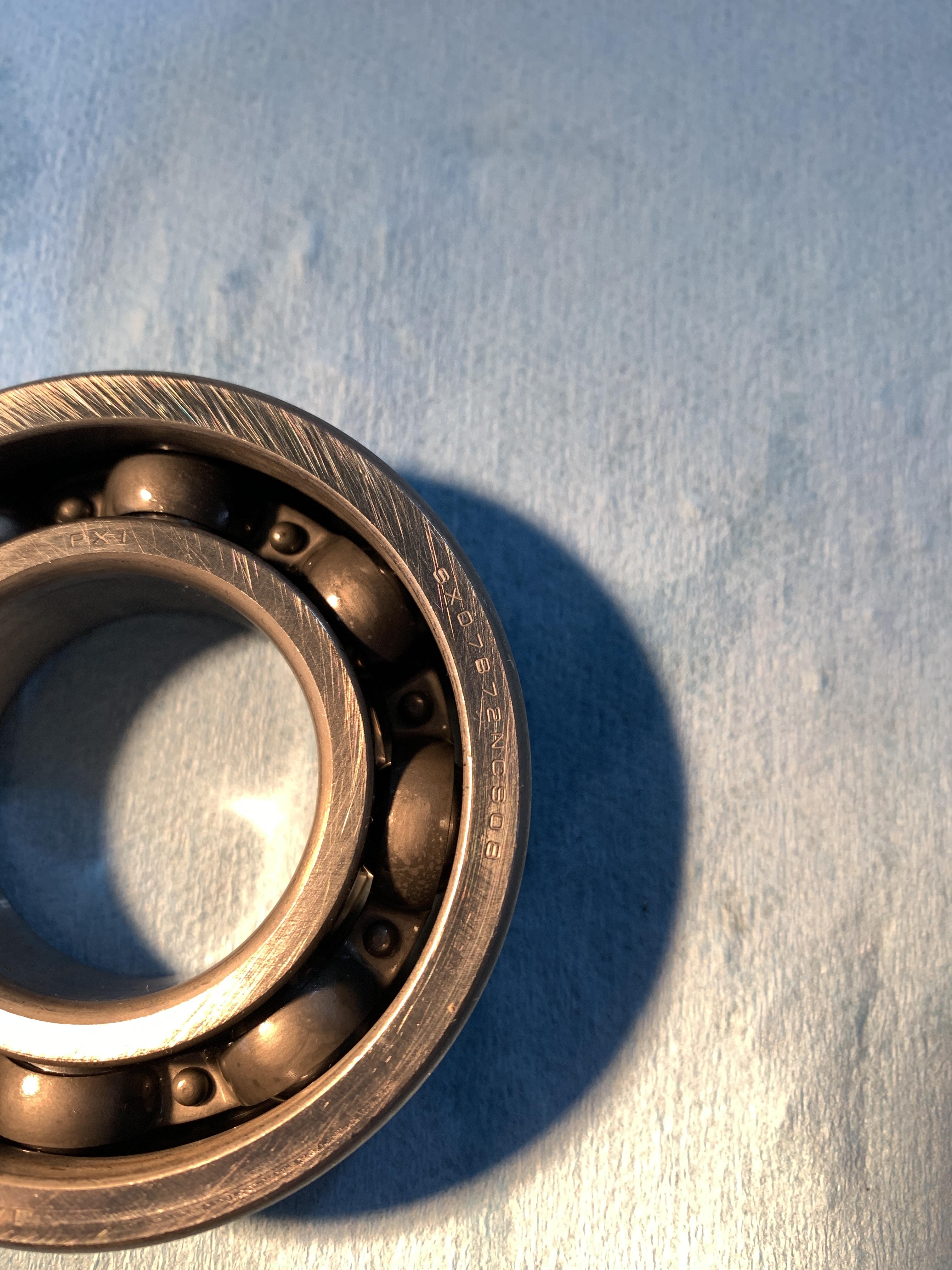
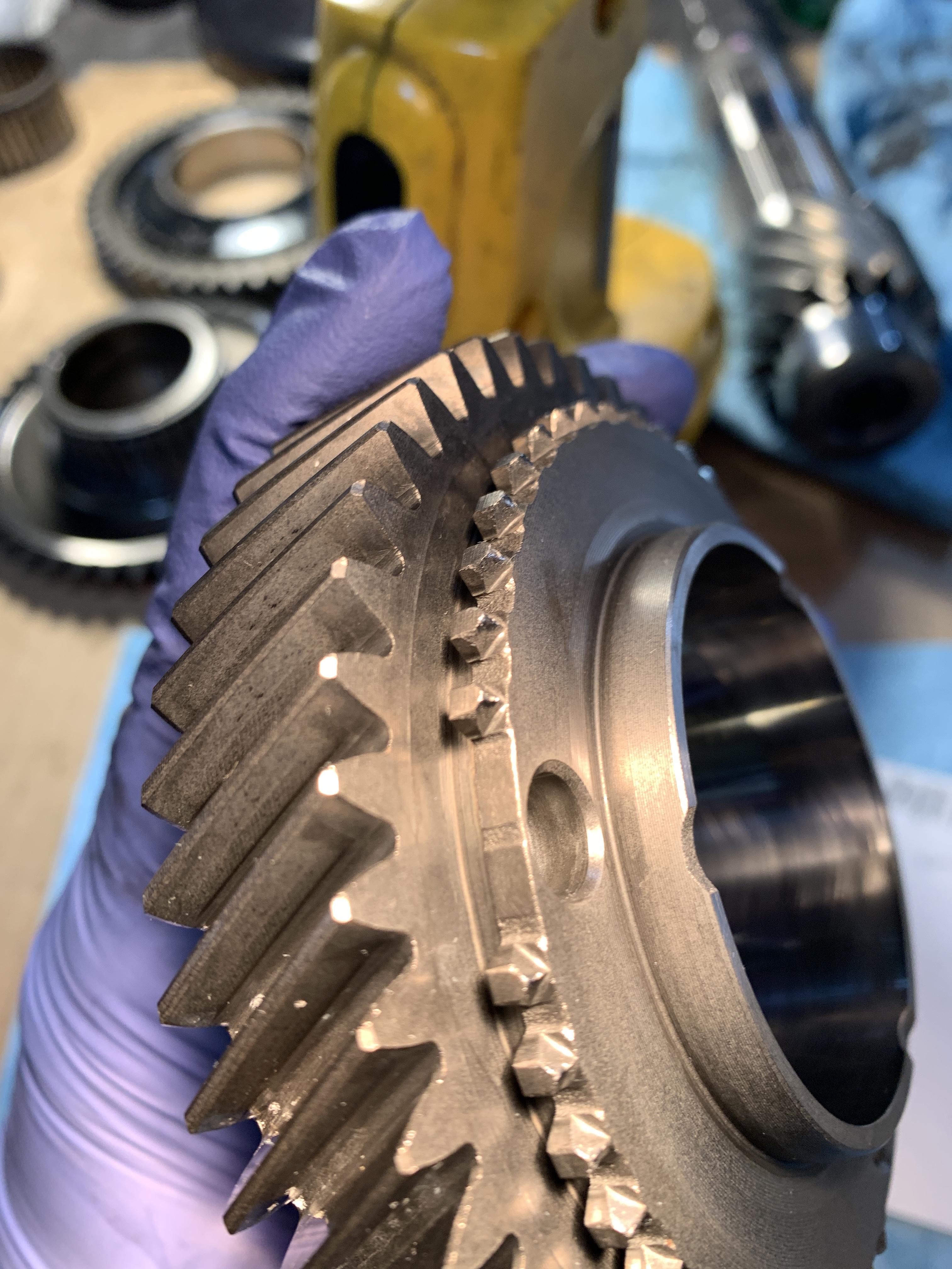
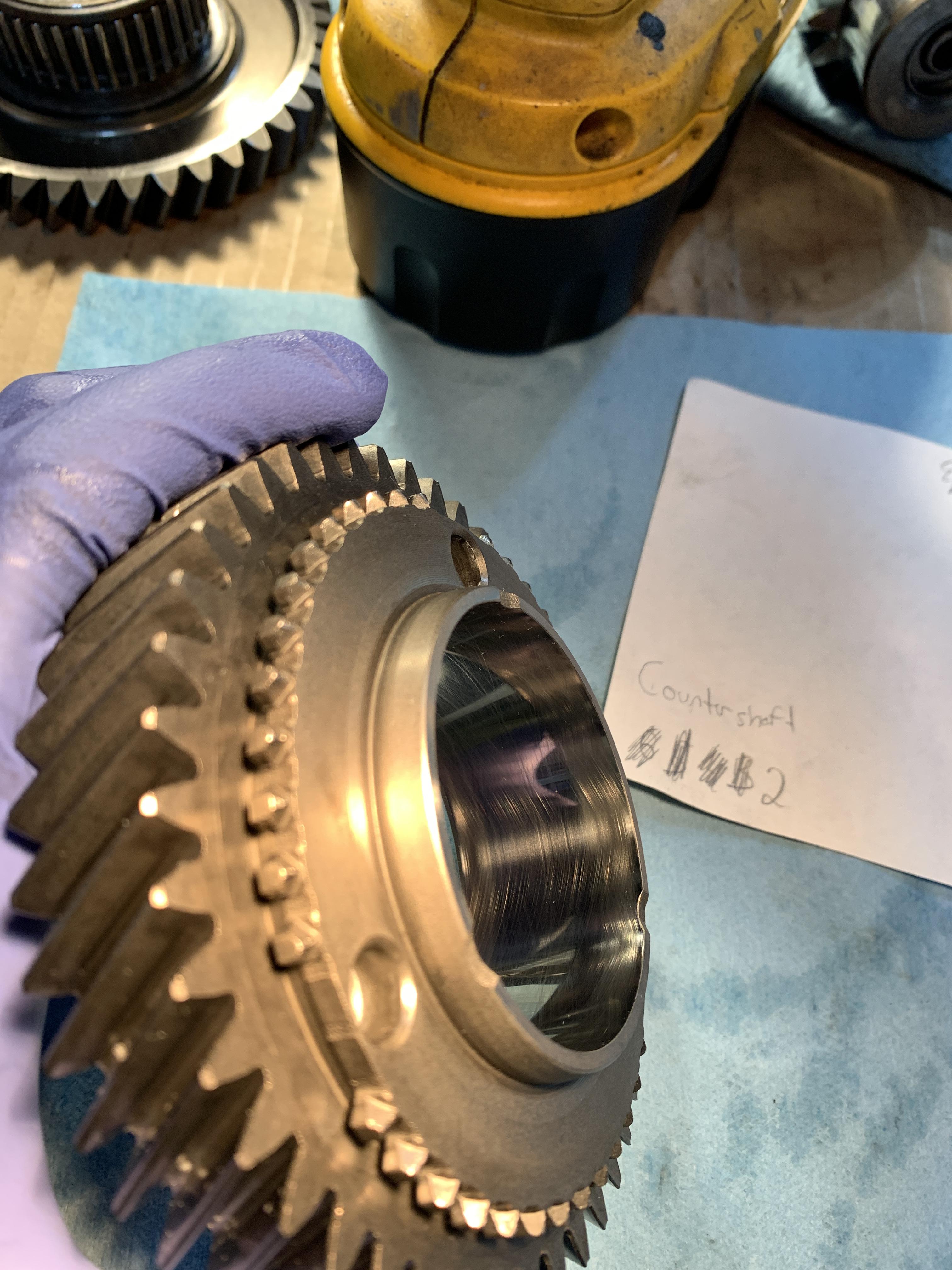
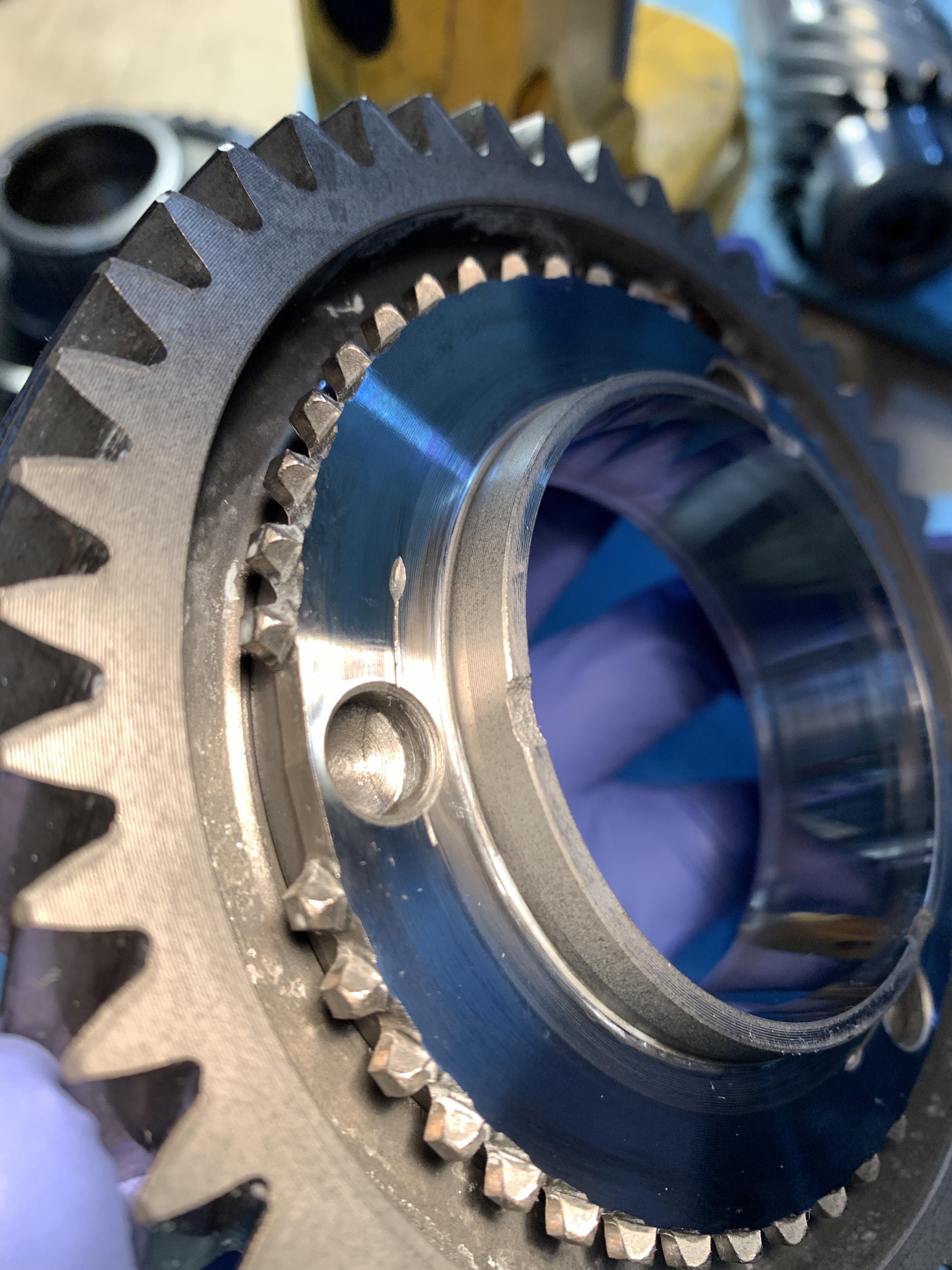
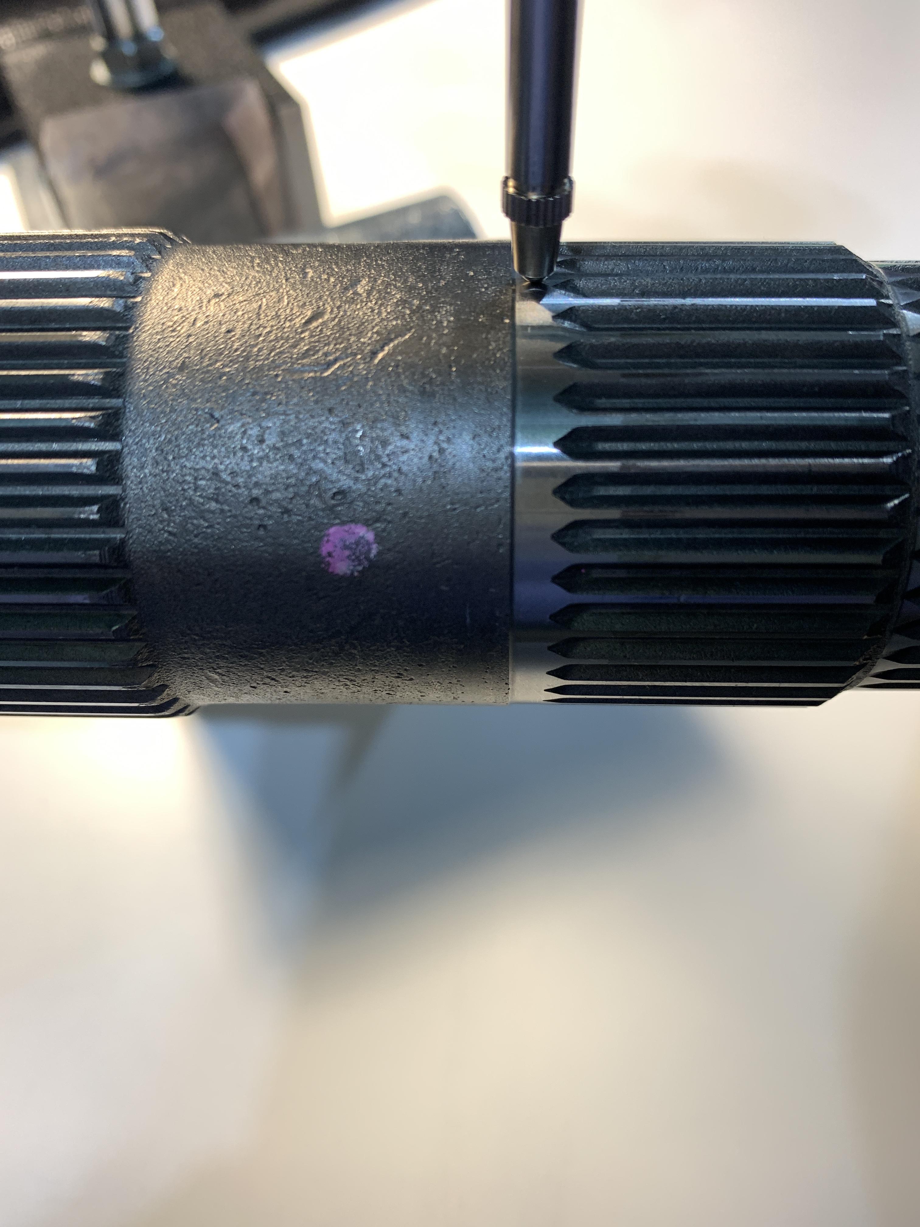
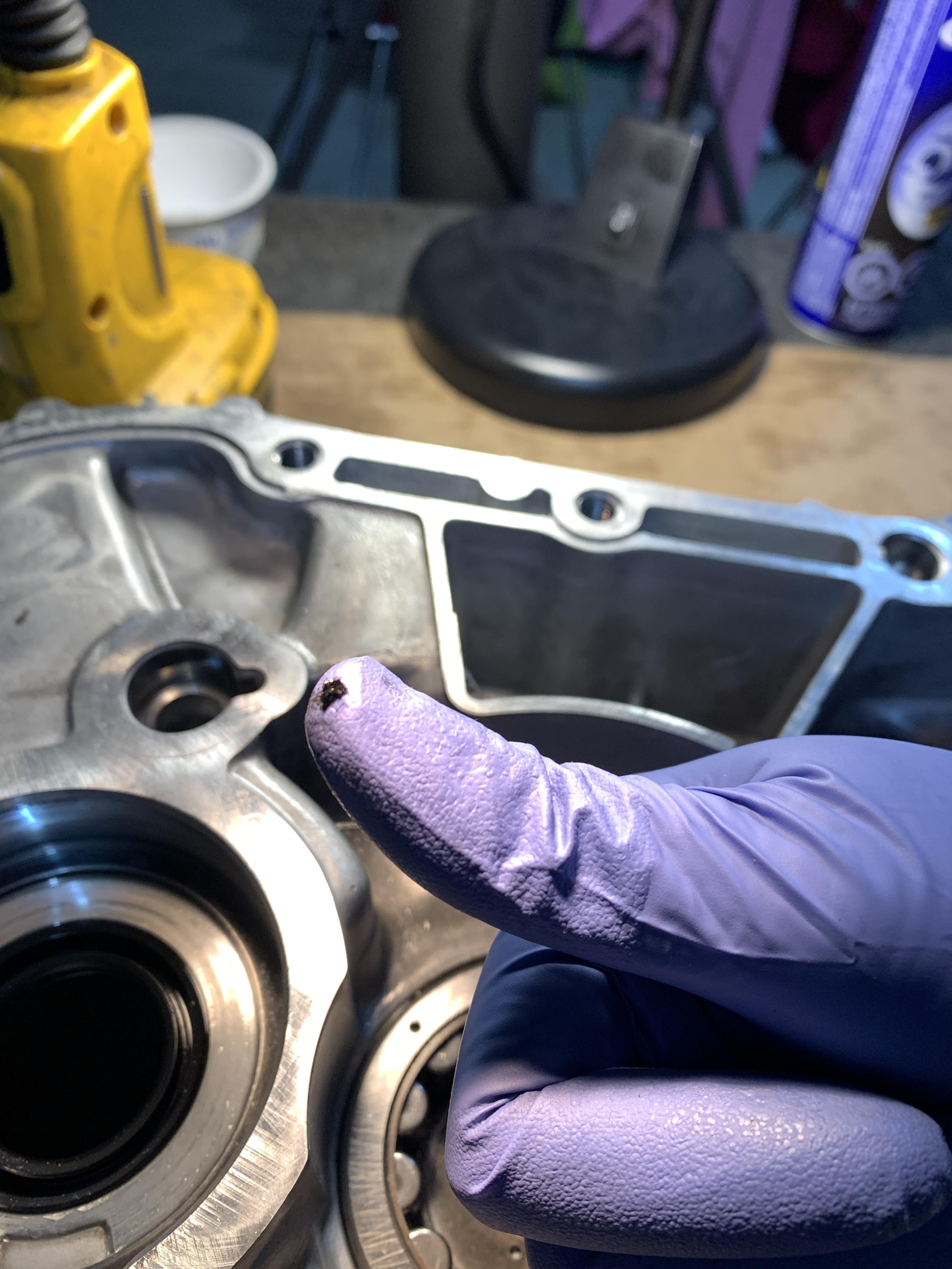
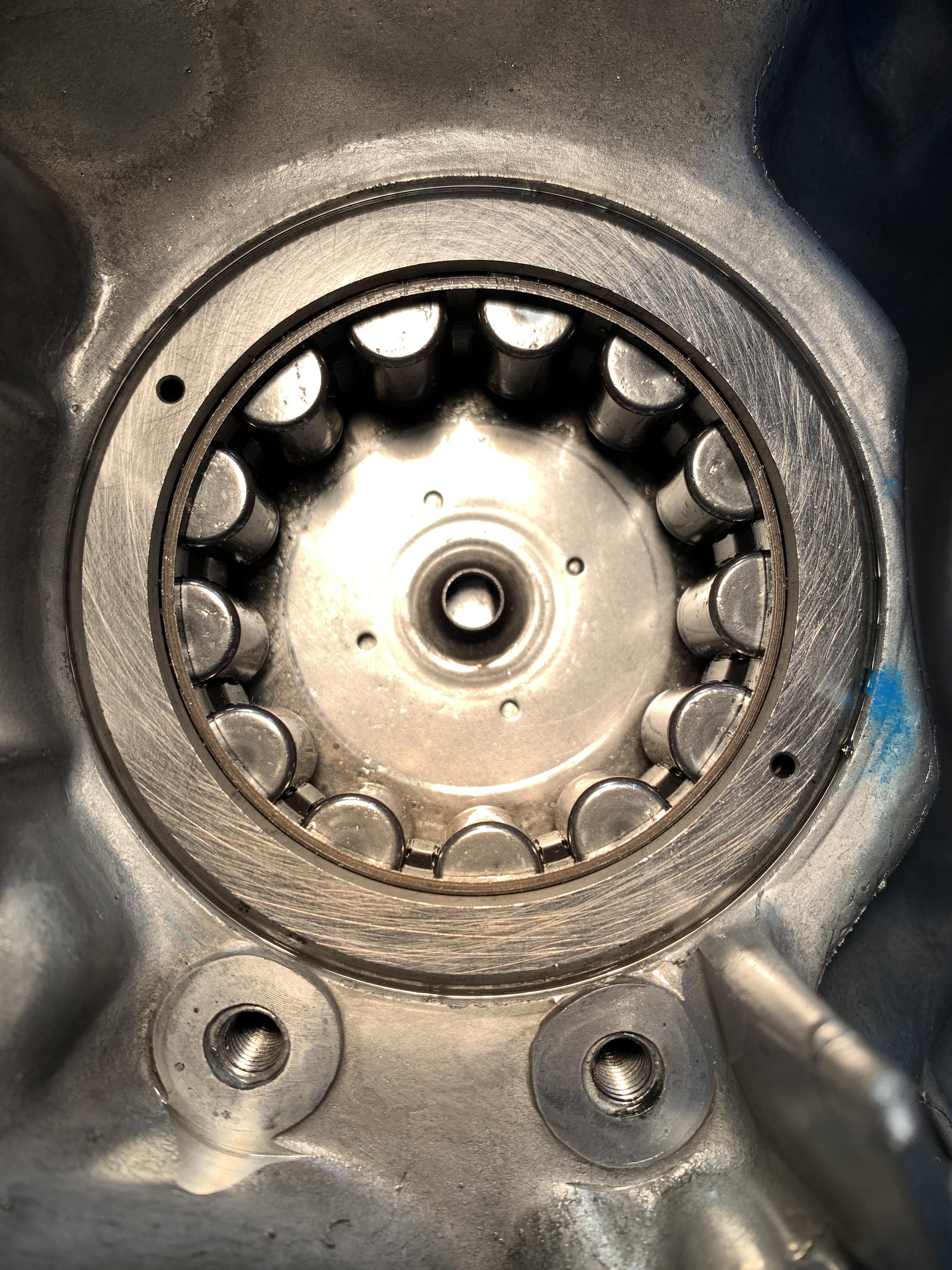
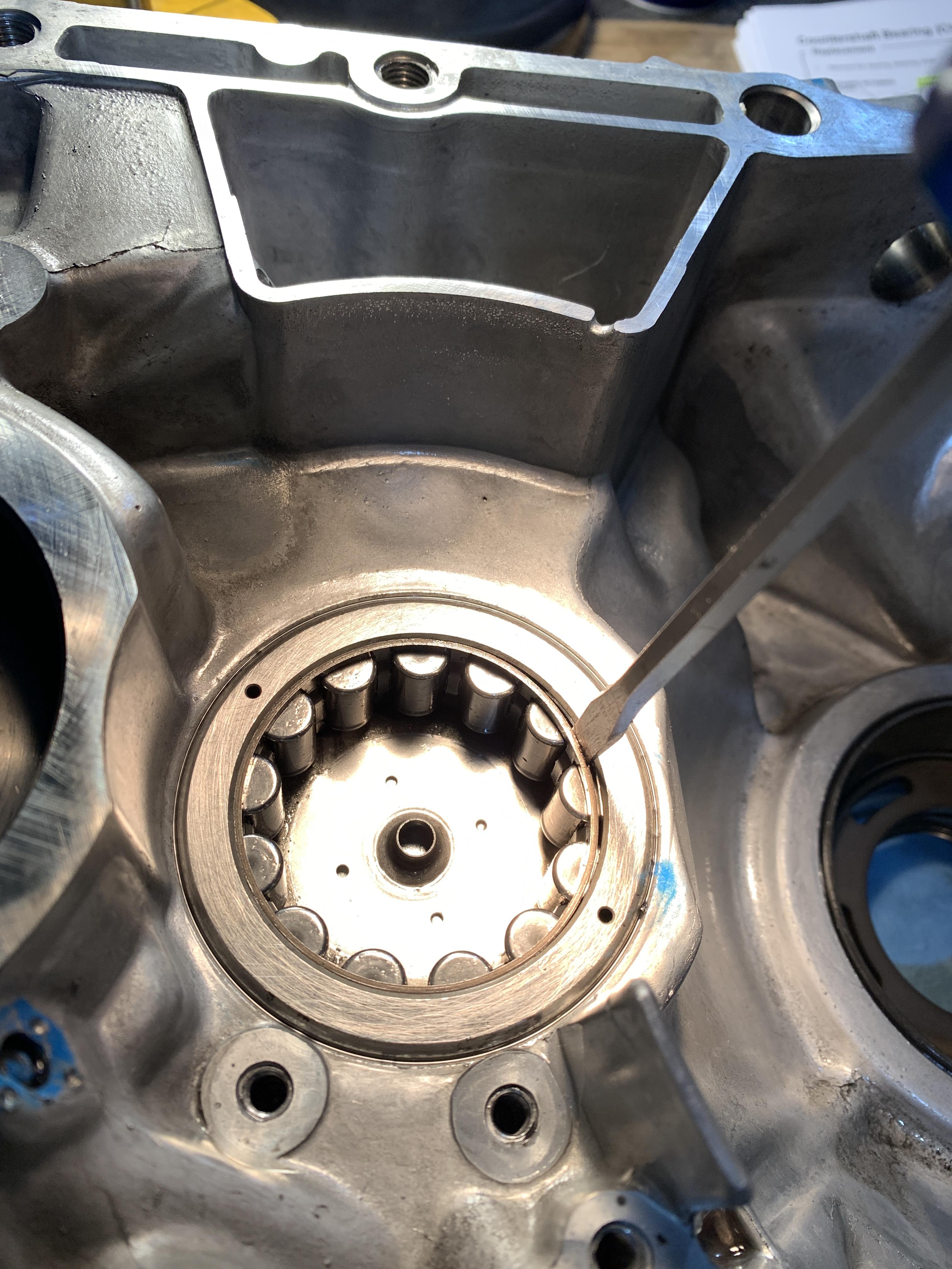
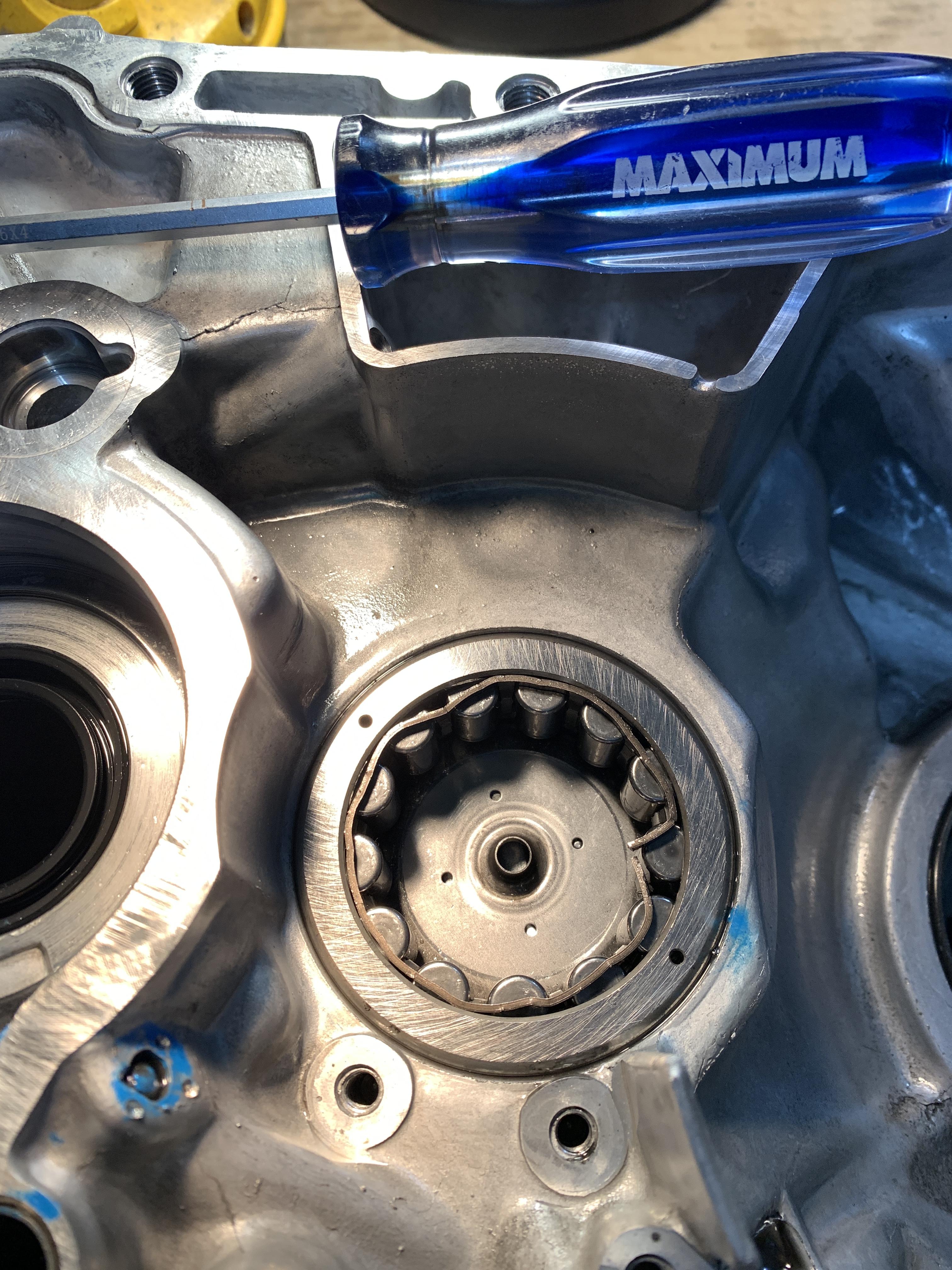
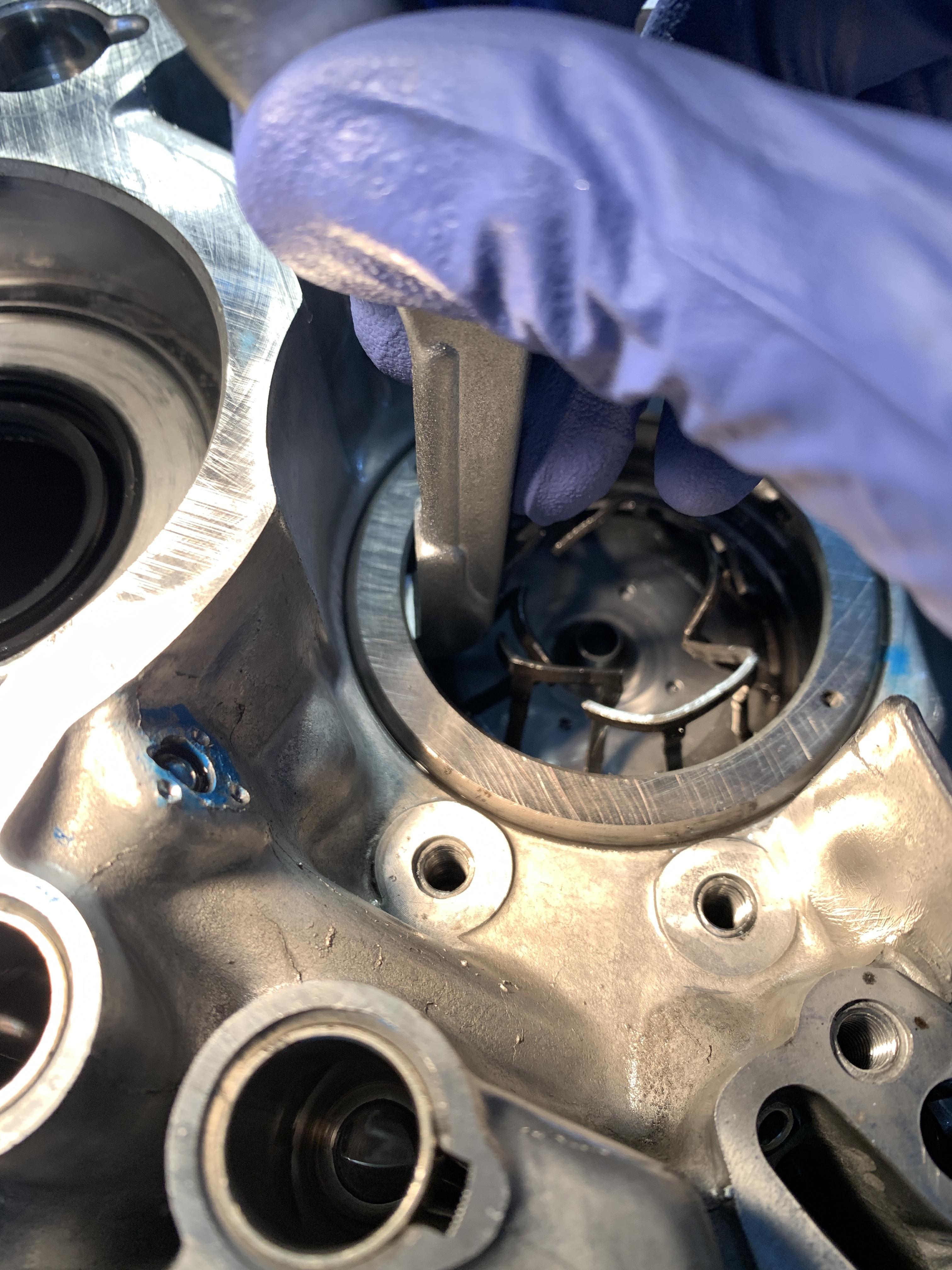
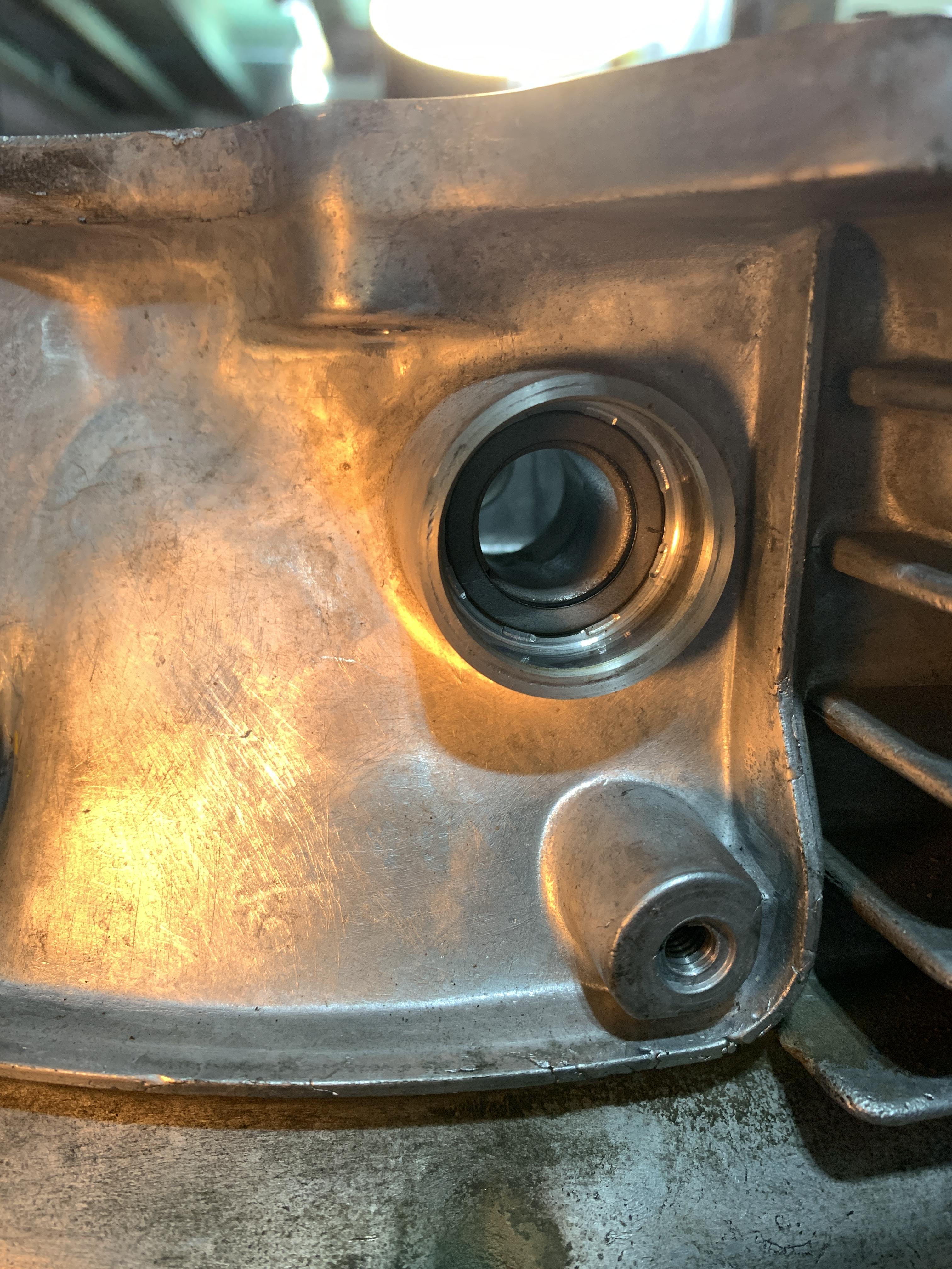
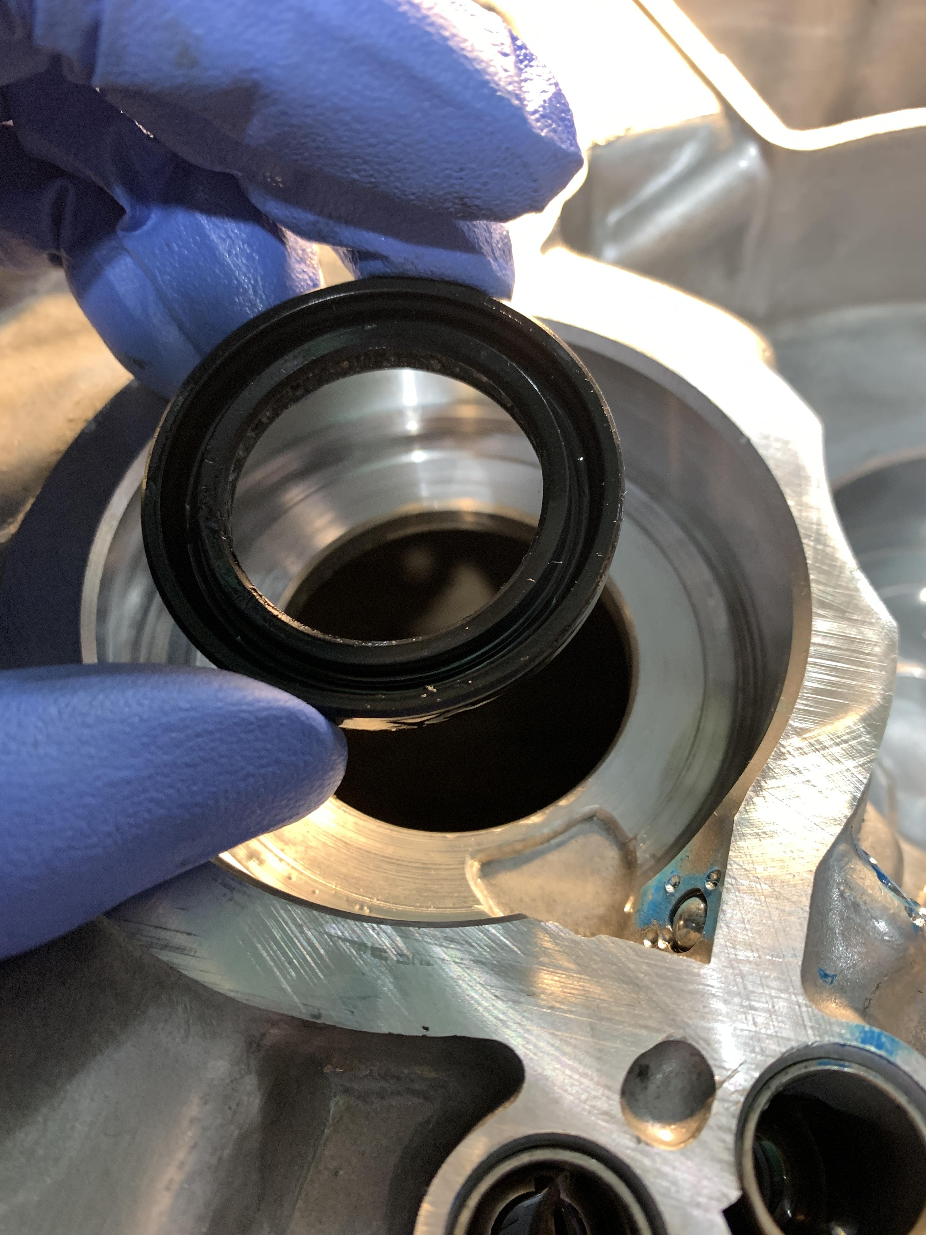
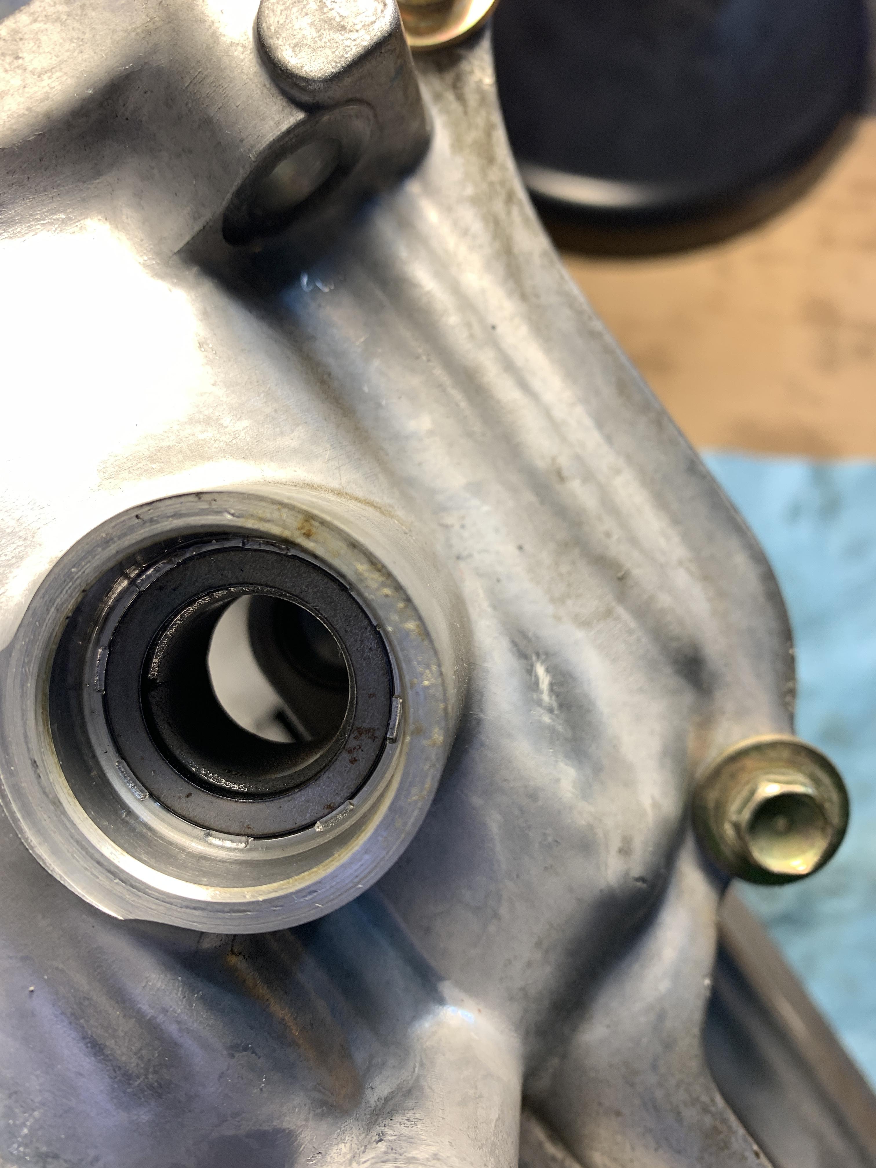
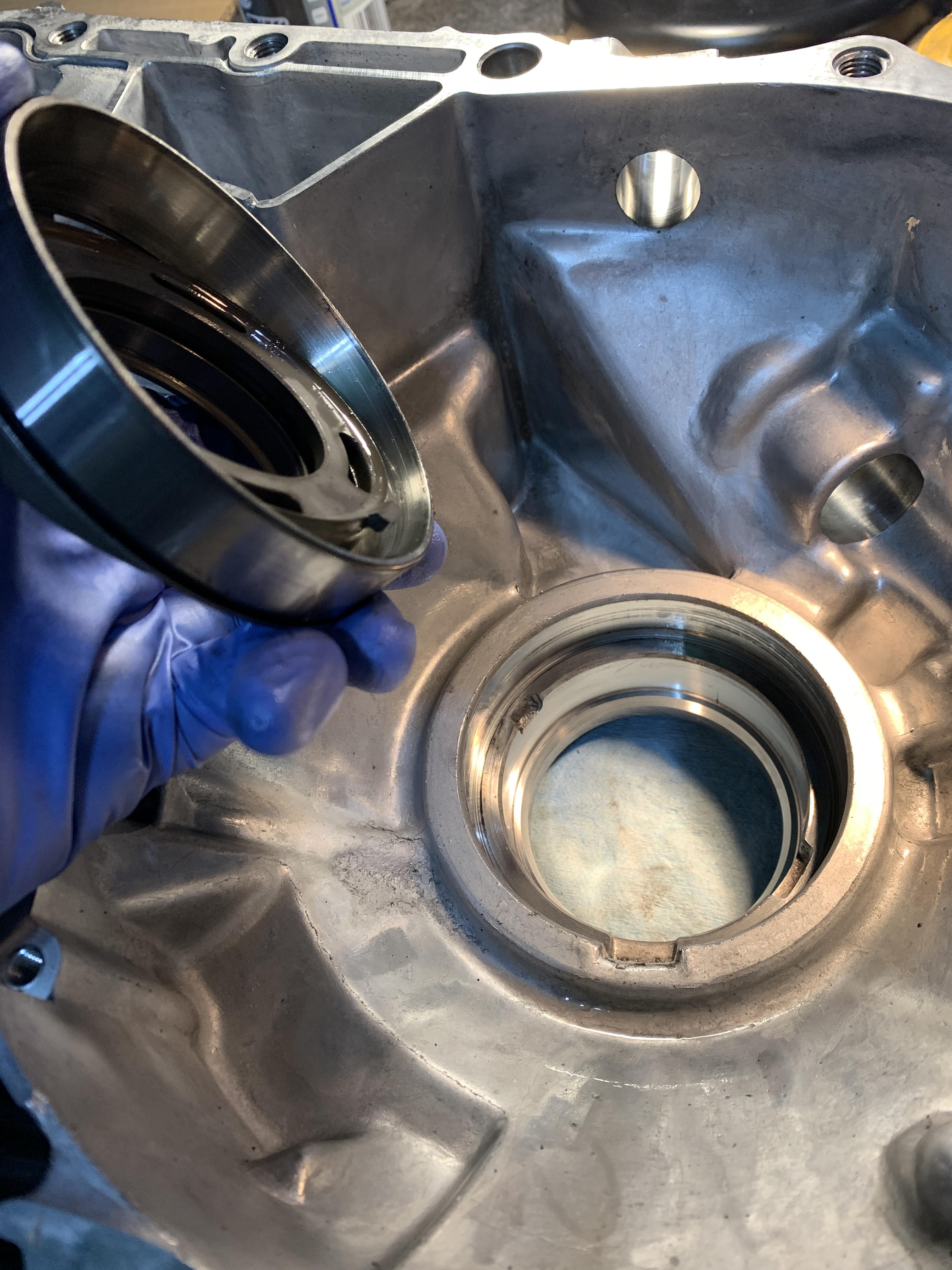
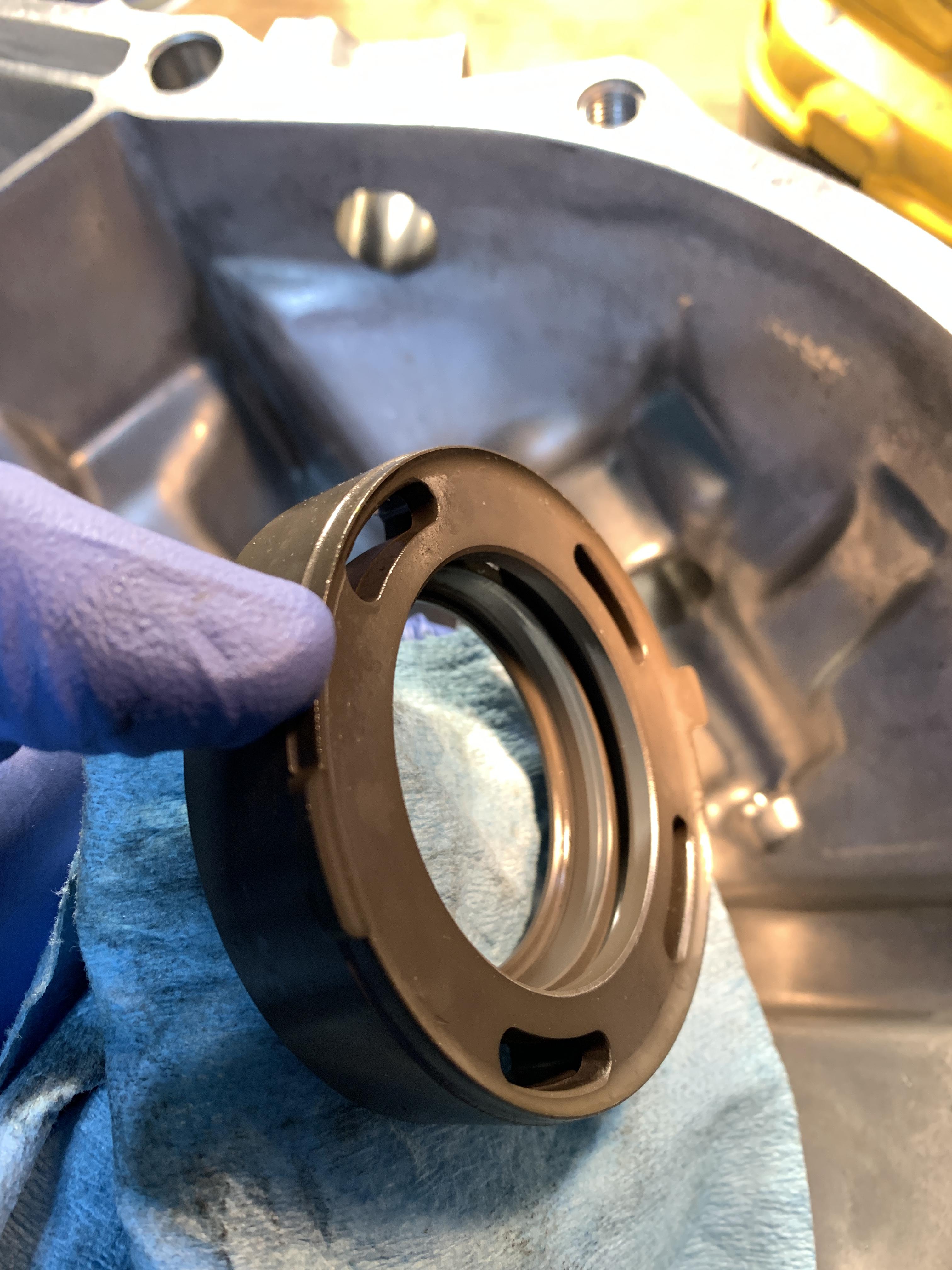
Also notice the lubrication ports so don’t have your needle skip over that.
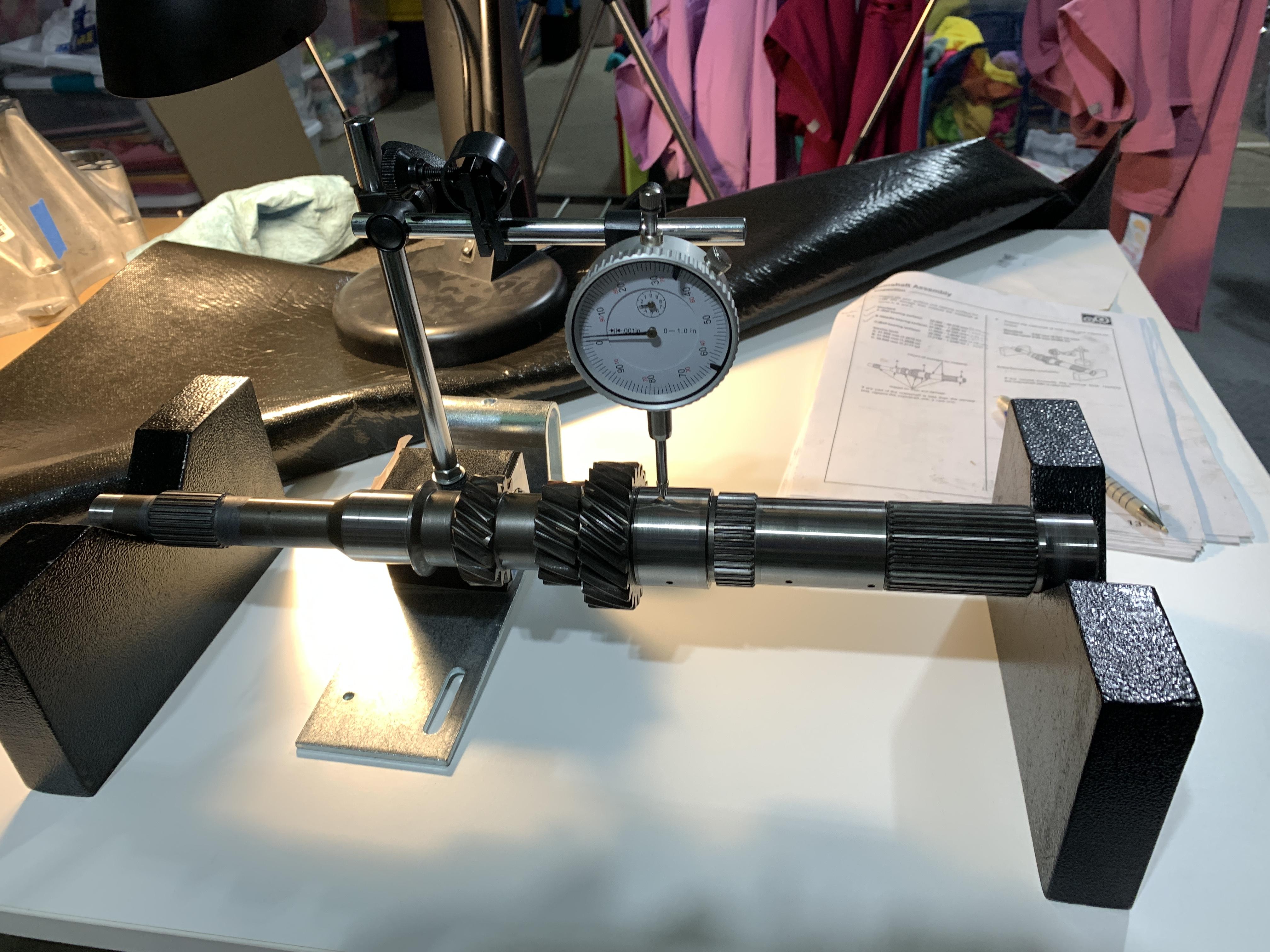
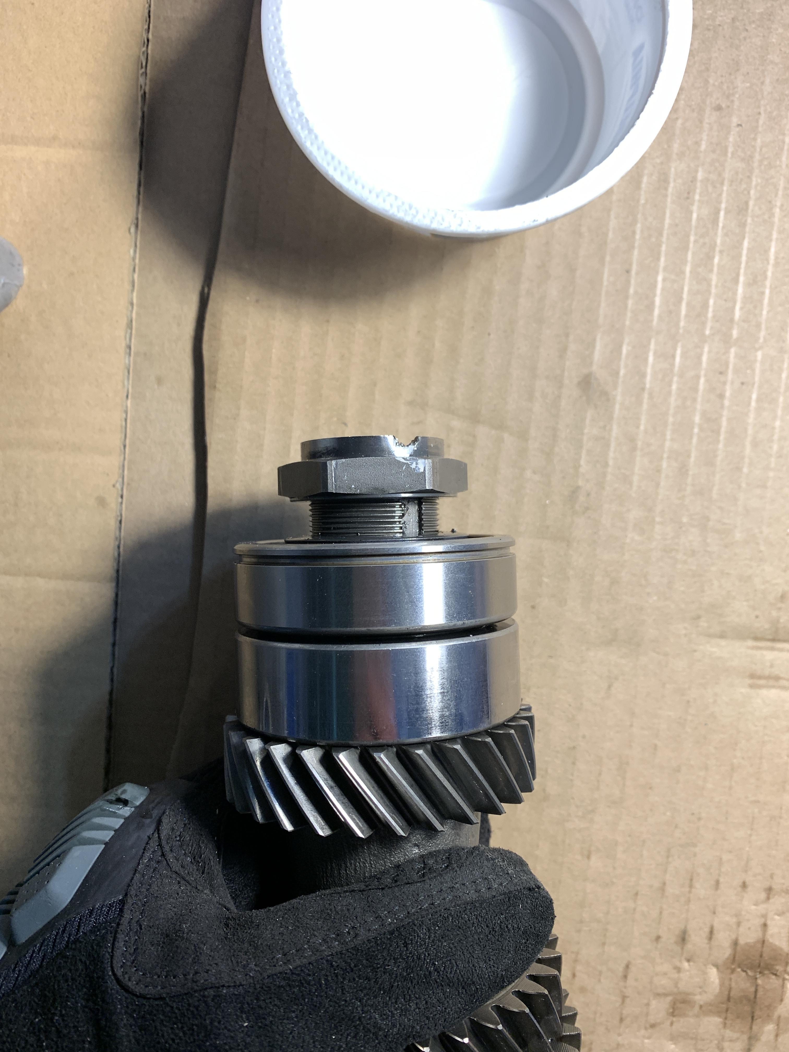
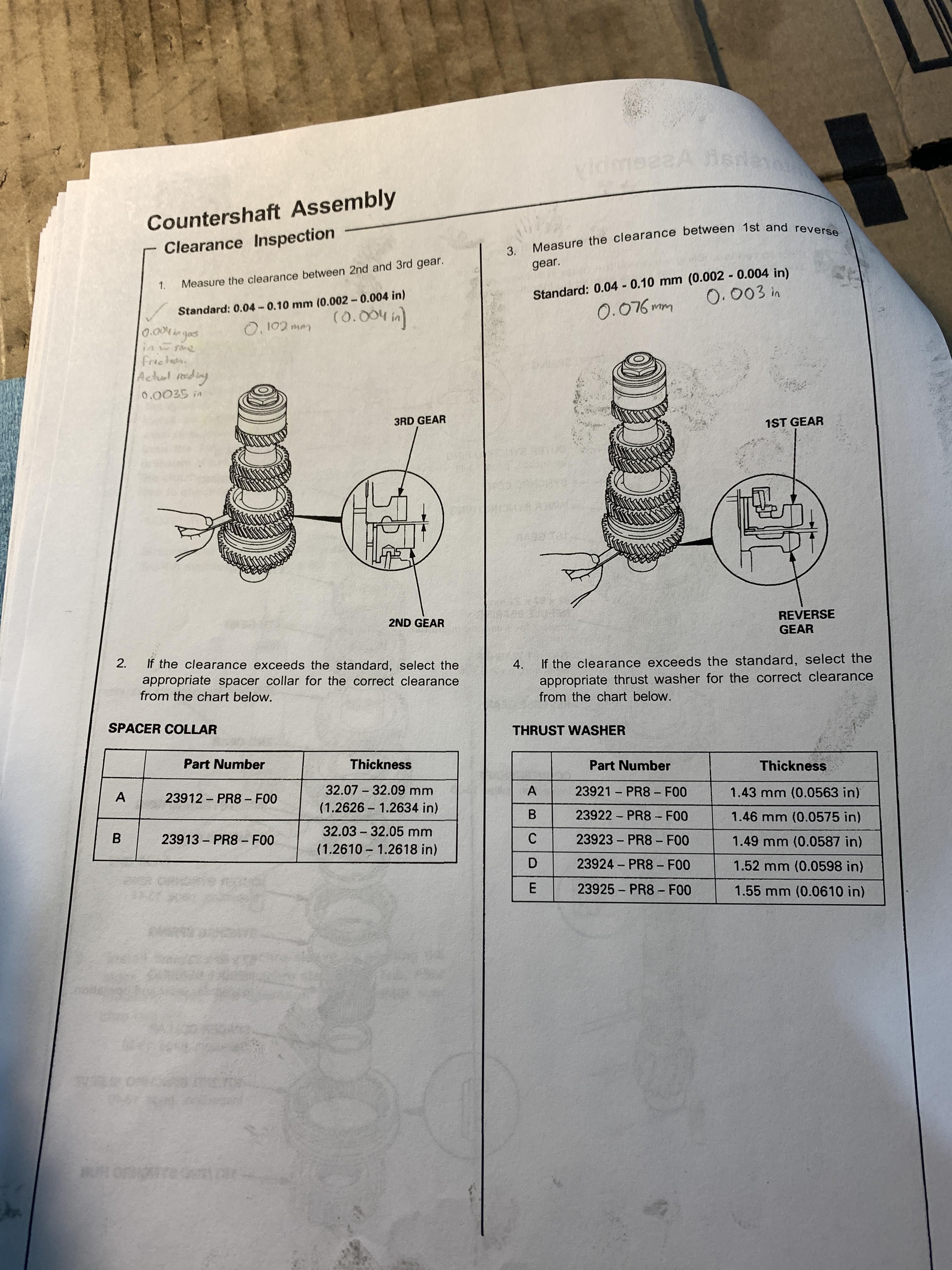
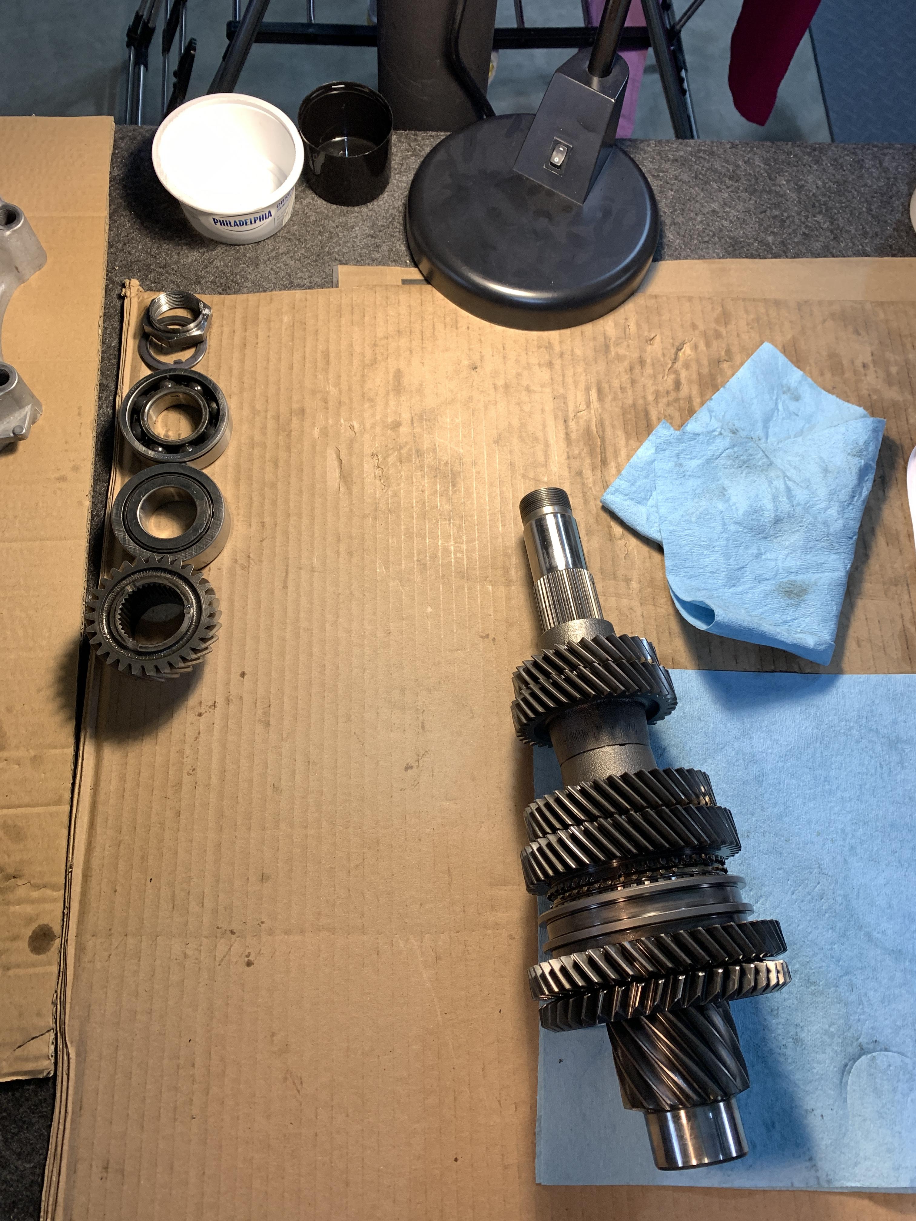
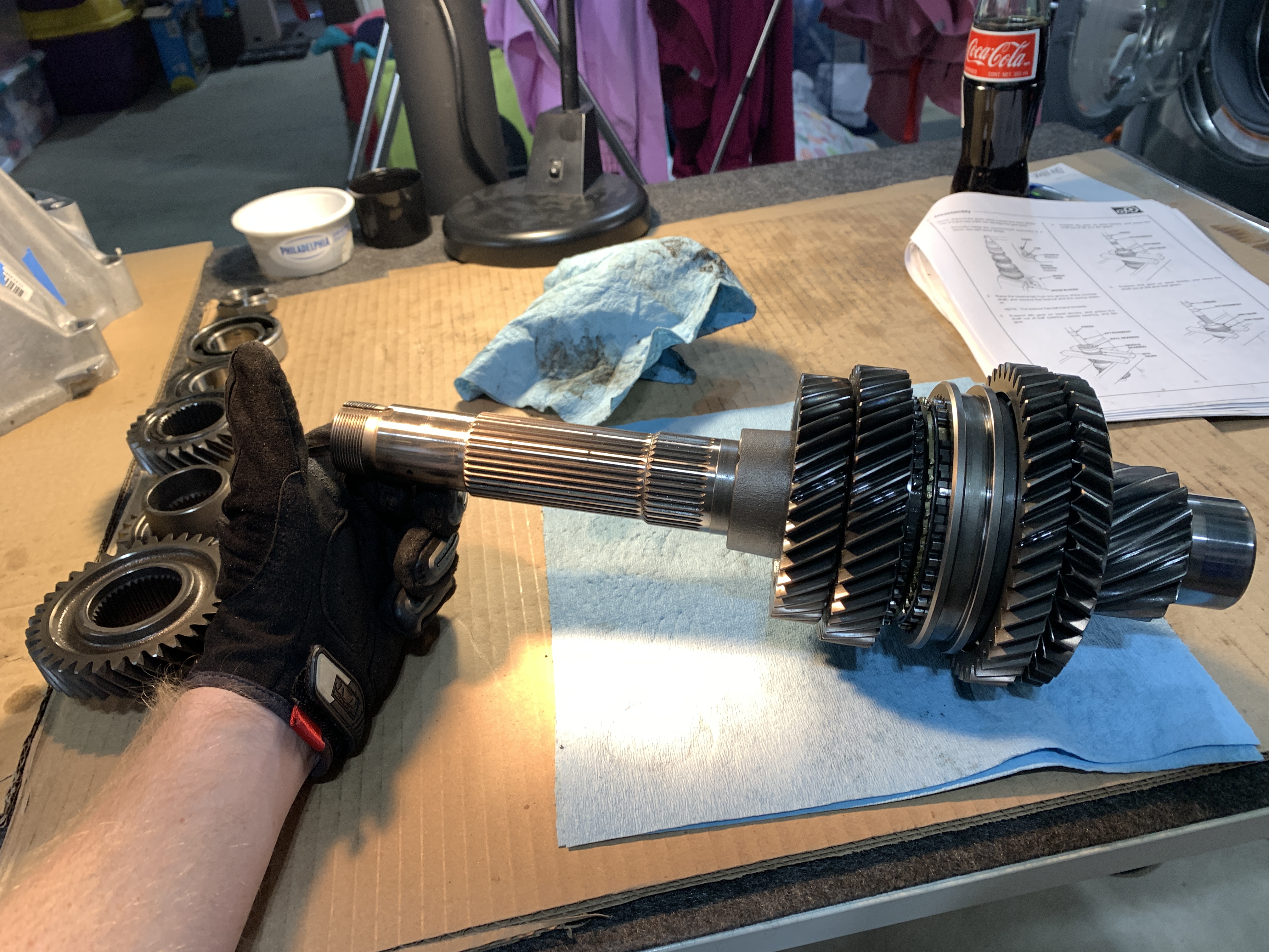
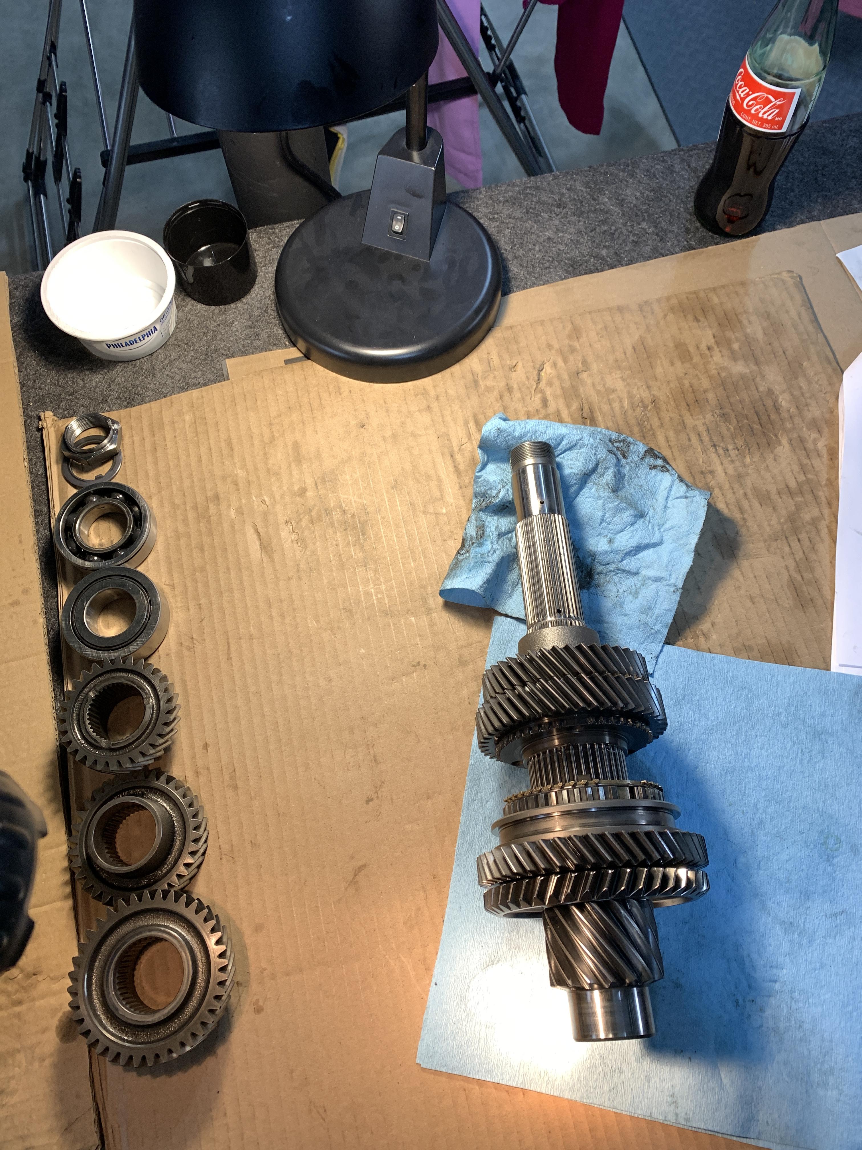
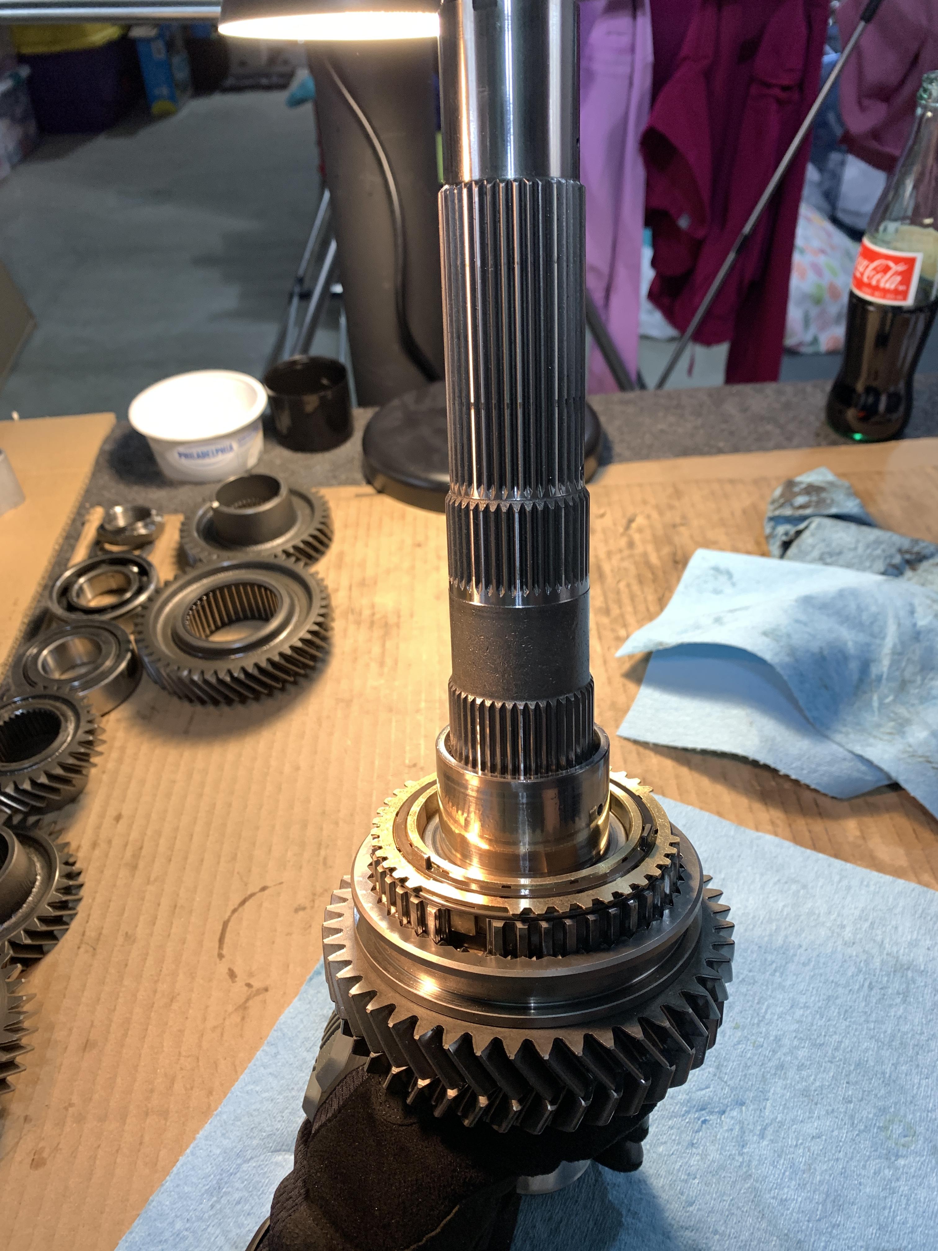
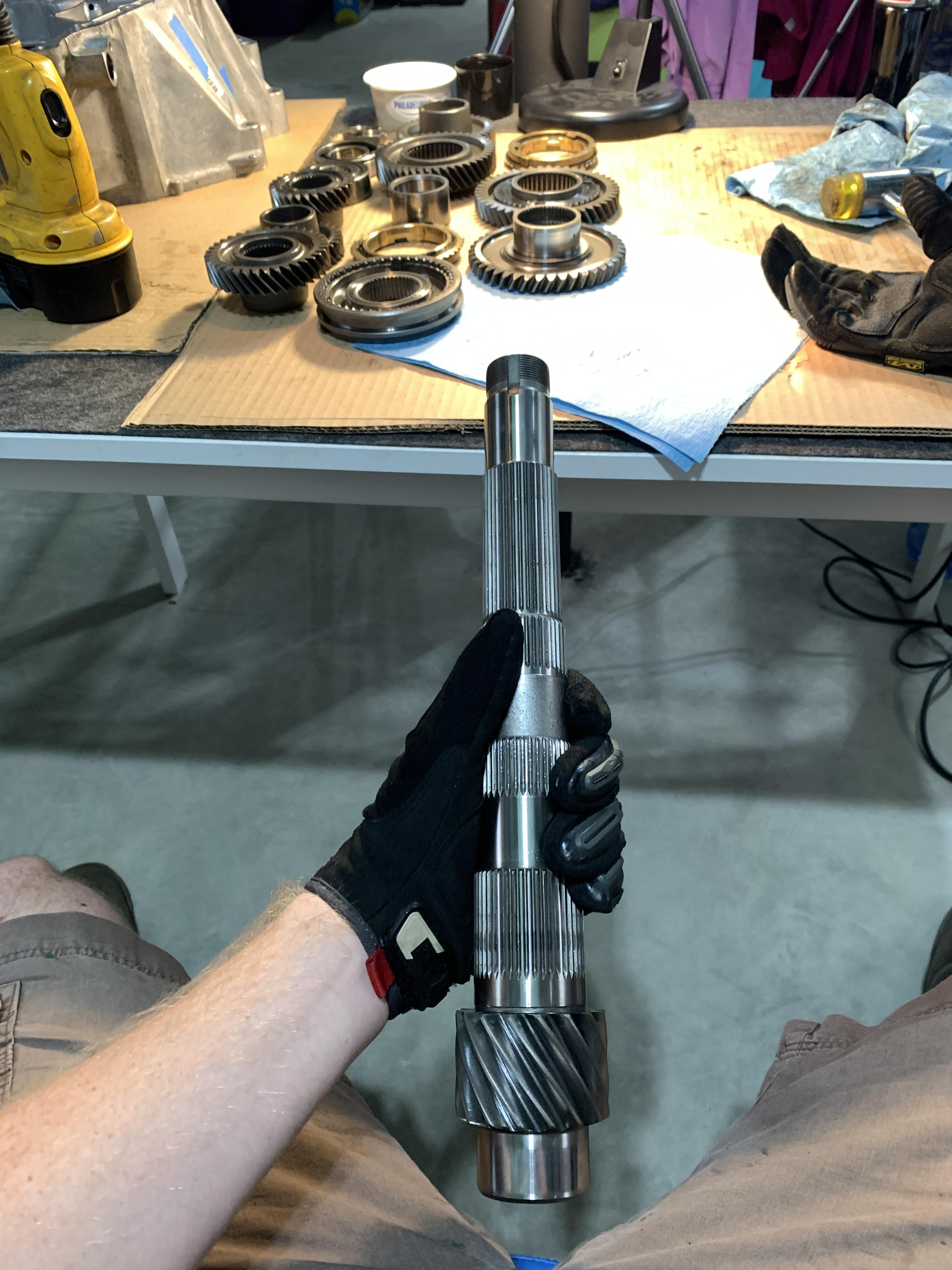
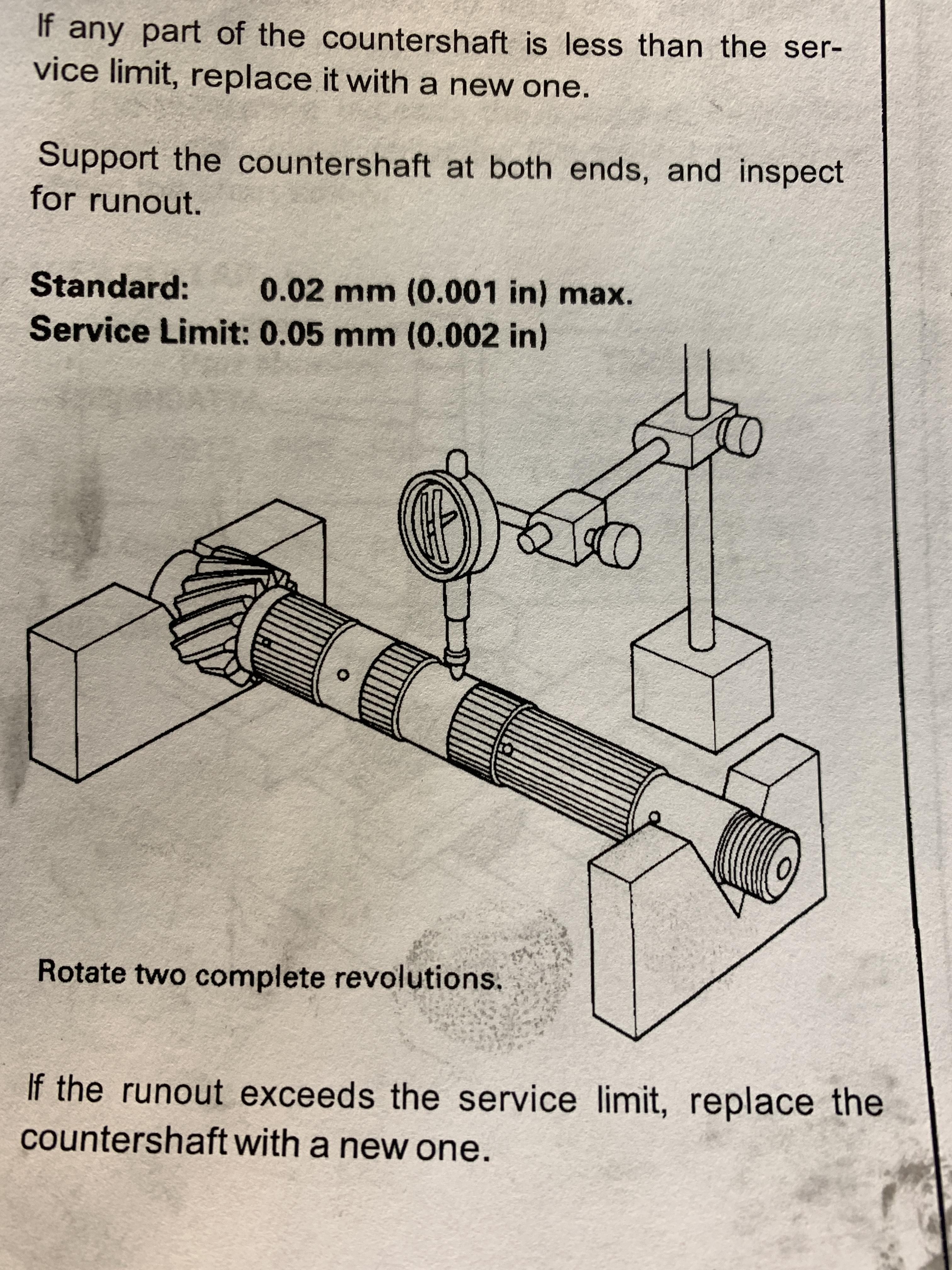
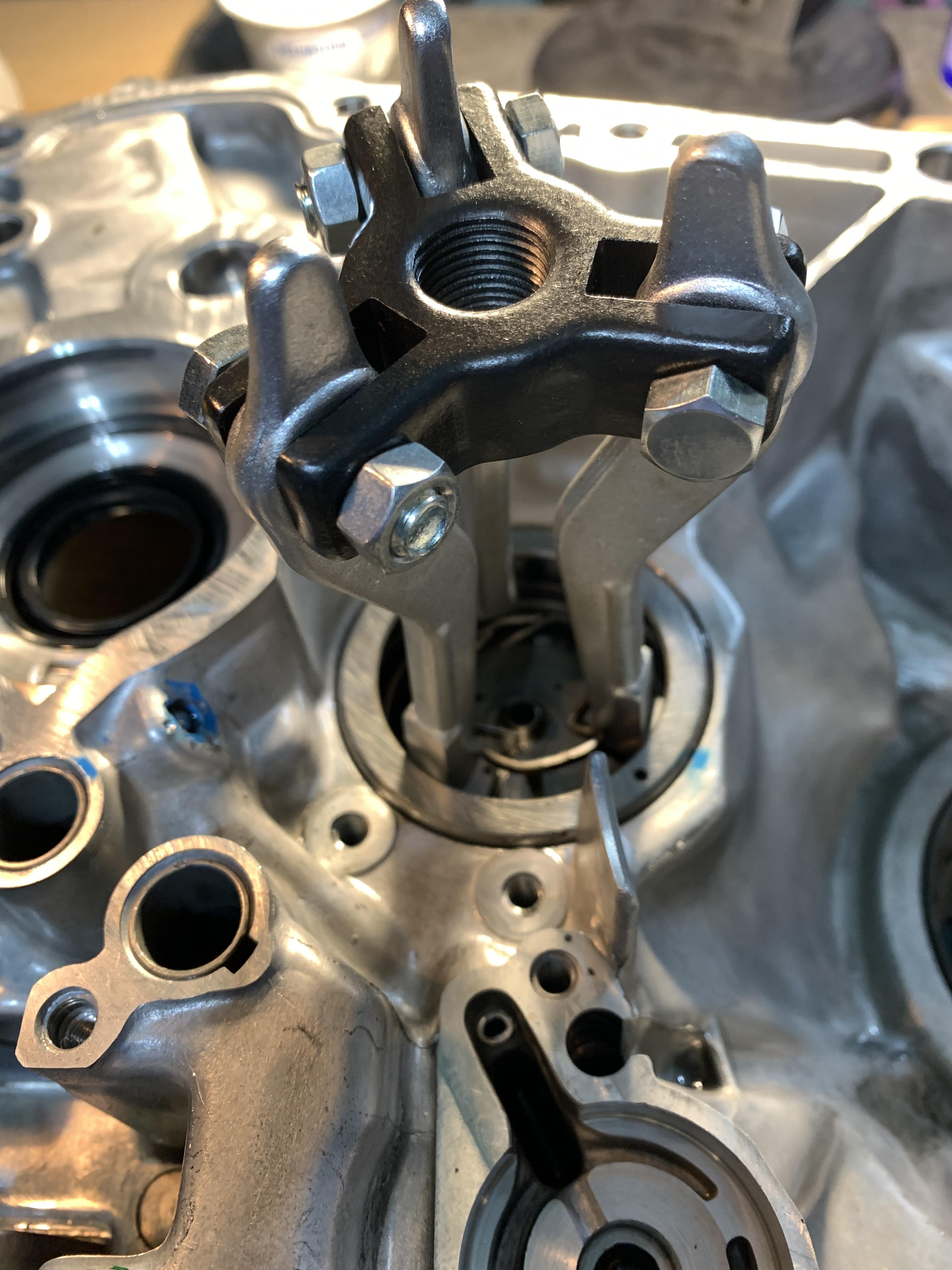
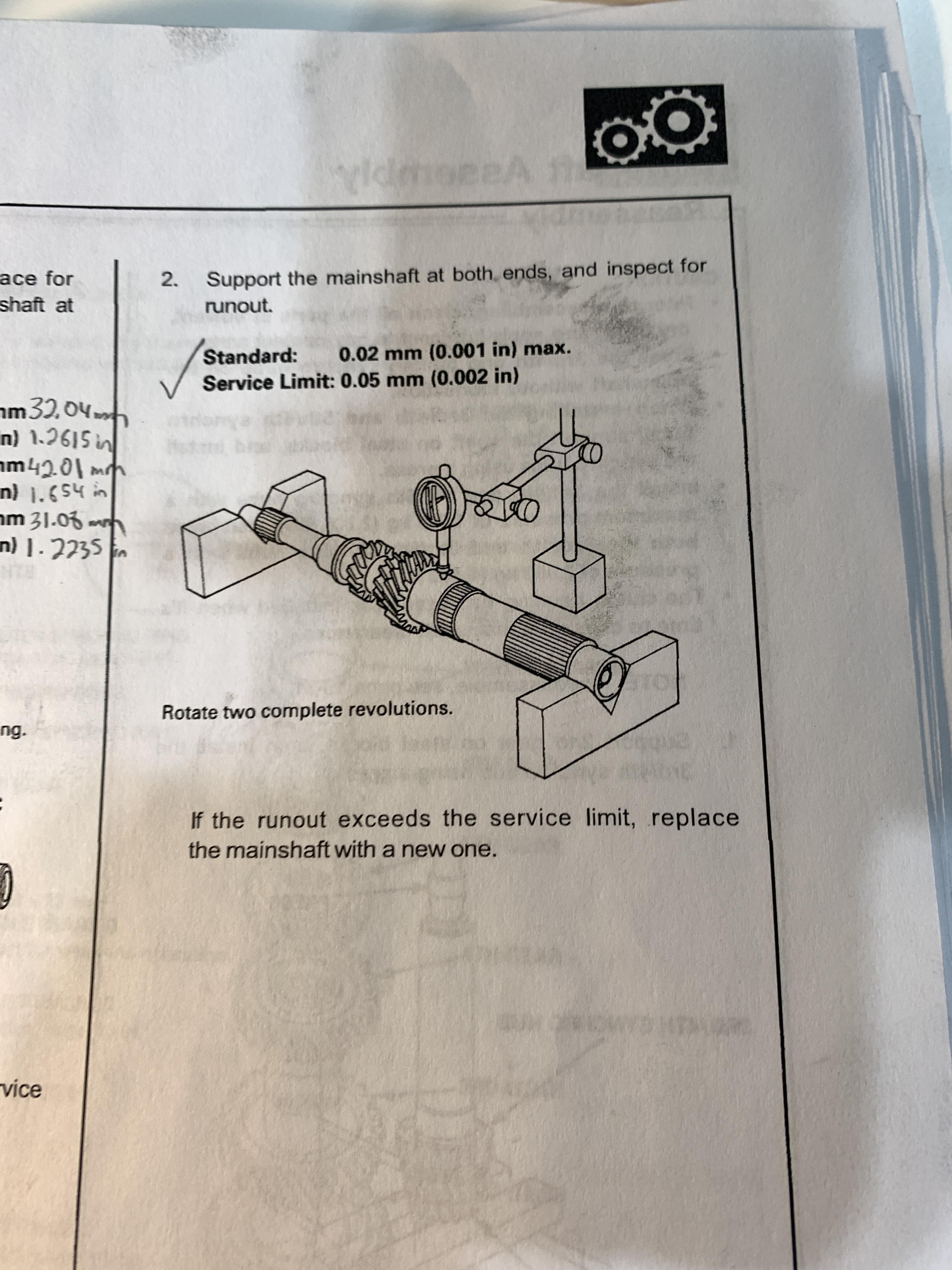
The service manual only calls out to measure the runout at 1 spot. I measured on all the flat surfaces where the bearings sit as well as close to the snout.
I used the press blocks to hold the shaft.
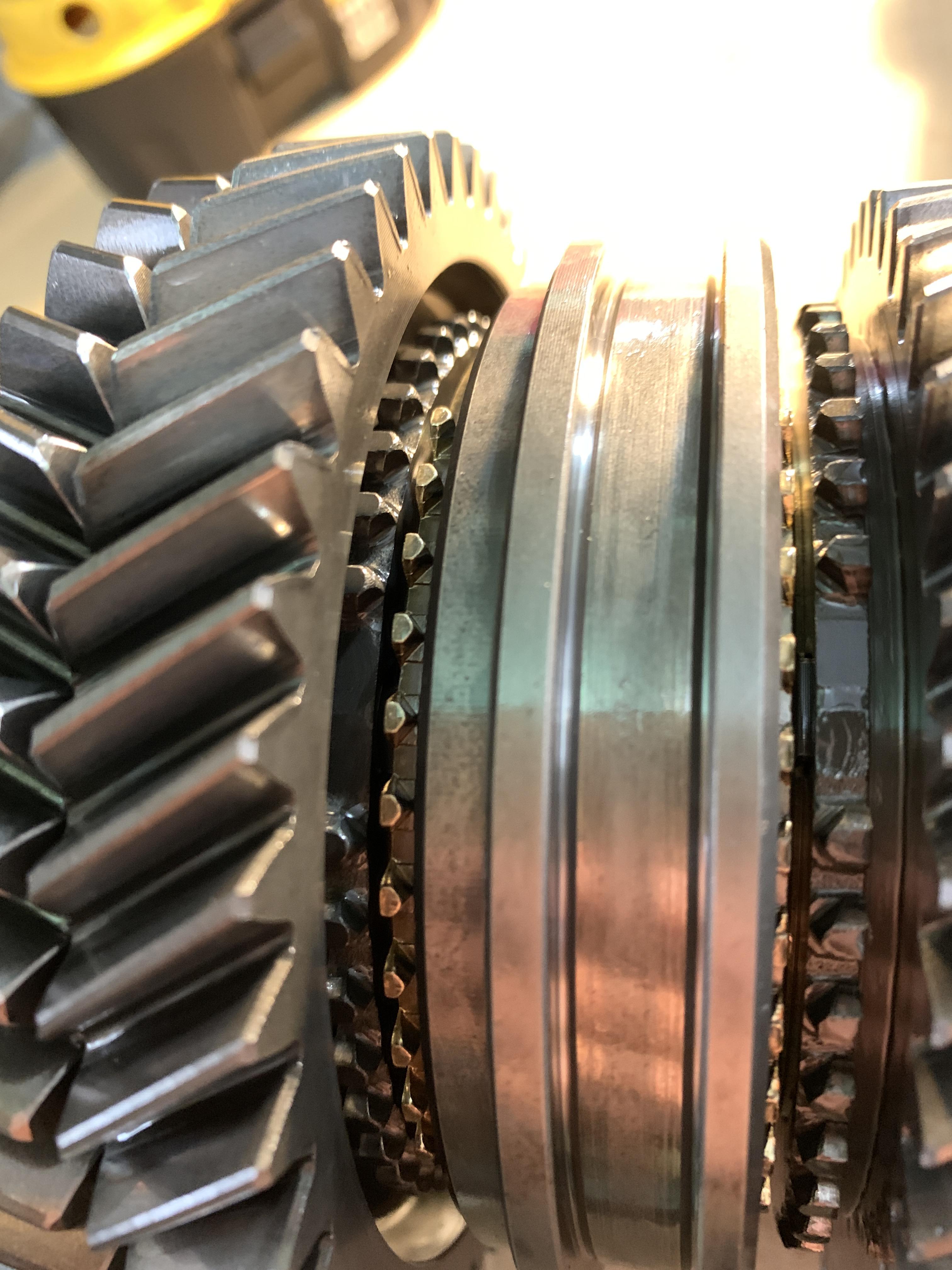
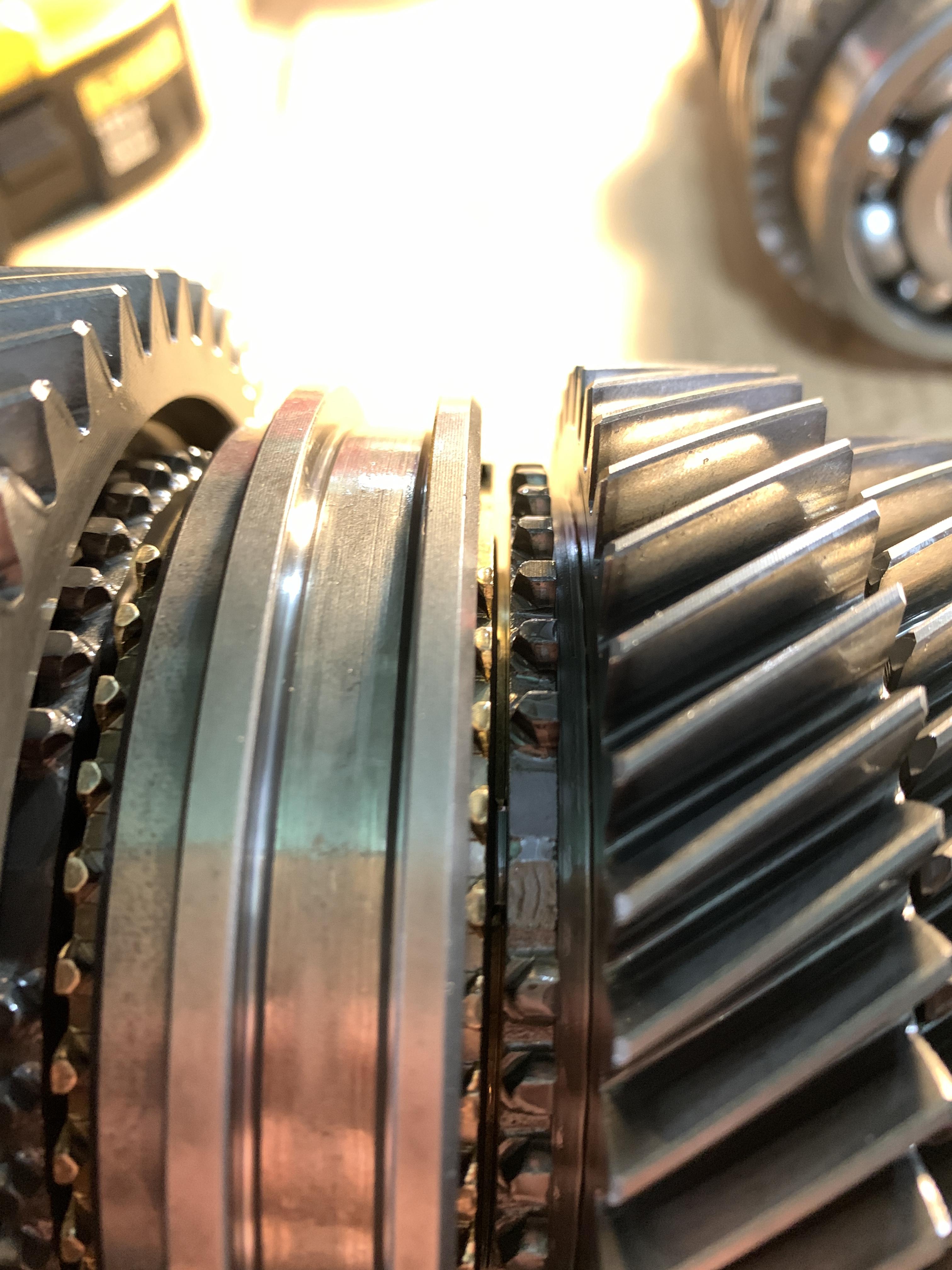
Also notice the lubrication ports so don’t have your needle skip over that.
The service manual only calls out to measure the runout at 1 spot. I measured on all the flat surfaces where the bearings sit as well as close to the snout.